overheating SKODA FABIA 2014 2.G / 5J Owner's Manual
[x] Cancel search | Manufacturer: SKODA, Model Year: 2014, Model line: FABIA, Model: SKODA FABIA 2014 2.G / 5JPages: 197, PDF Size: 13.56 MB
Page 29 of 197
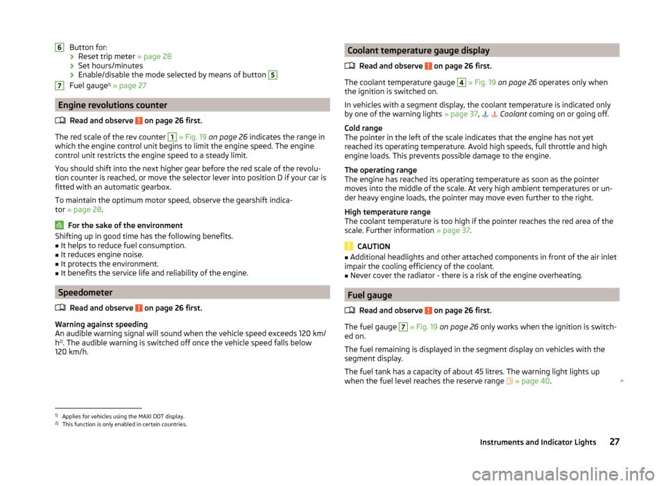
Button for:› Reset trip meter
» page 28
› Set hours/minutes
› Enable/disable the mode selected by means of button 5
Fuel gauge 1)
» page 27
Engine revolutions counter
Read and observe
on page 26 first.
The red scale of the rev counter
1
» Fig. 19 on page 26 indicates the range in
which the engine control unit begins to limit the engine speed. The engine
control unit restricts the engine speed to a steady limit.
You should shift into the next higher gear before the red scale of the revolu- tion counter is reached, or move the selector lever into position D if your car is
fitted with an automatic gearbox.
To maintain the optimum motor speed, observe the gearshift indica-
tor » page 28 .
For the sake of the environment
Shifting up in good time has the following benefits.■It helps to reduce fuel consumption.■
It reduces engine noise.
■
It protects the environment.
■
It benefits the service life and reliability of the engine.
Speedometer
Read and observe
on page 26 first.
Warning against speeding
An audible warning signal will sound when the vehicle speed exceeds 120 km/
h 2)
. The audible warning is switched off once the vehicle speed falls below
120 km/h.
67Coolant temperature gauge display
Read and observe
on page 26 first.
The coolant temperature gauge
4
» Fig. 19 on page 26 operates only when
the ignition is switched on.
In vehicles with a segment display, the coolant temperature is indicated only
by one of the warning lights » page 37,
Coolant coming on or going off.
Cold range
The pointer in the left of the scale indicates that the engine has not yet
reached its operating temperature. Avoid high speeds, full throttle and high engine loads. This prevents possible damage to the engine.
The operating range
The engine has reached its operating temperature as soon as the pointer
moves into the middle of the scale. At very high ambient temperatures or un-
der heavy engine loads, the pointer may move even further to the right.
High temperature range
The coolant temperature is too high if the pointer reaches the red area of the
scale. Further information » page 37.
CAUTION
■
Additional headlights and other attached components in front of the air inlet
impair the cooling efficiency of the coolant.■
Never cover the radiator - there is a risk of the engine overheating.
Fuel gauge
Read and observe
on page 26 first.
The fuel gauge
7
» Fig. 19 on page 26 only works when the ignition is switch-
ed on.
The fuel remaining is displayed in the segment display on vehicles with the
segment display.
The fuel tank has a capacity of about 45 litres. The warning light lights up
when the fuel level reaches the reserve range
» page 40 .
1)
Applies for vehicles using the MAXI DOT display.
2)
This function is only enabled in certain countries.
27Instruments and Indicator Lights
Page 39 of 197
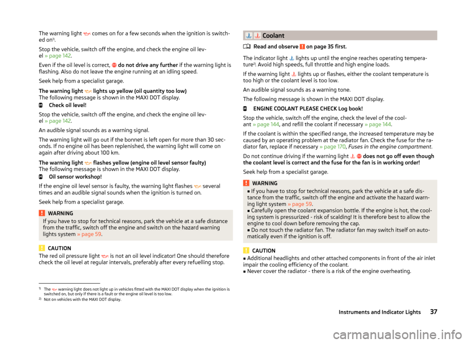
The warning light comes on for a few seconds when the ignition is switch-
ed on 1)
.
Stop the vehicle, switch off the engine, and check the engine oil lev-
el » page 142 .
Even if the oil level is correct,
do not drive any further if the warning light is
flashing. Also do not leave the engine running at an idling speed.
Seek help from a specialist garage.
The warning light
lights up yellow (oil quantity too low)
The following message is shown in the MAXI DOT display.
Check oil level!
Stop the vehicle, switch off the engine, and check the engine oil lev-
el » page 142 .
An audible signal sounds as a warning signal.
The warning light will go out if the bonnet is left open for more than 30 sec-
onds. If no engine oil has been replenished, the warning light will come on
again after driving about 100 km.
The warning light flashes yellow (engine oil level sensor faulty)
The following message is shown in the MAXI DOT display.
Oil sensor workshop!
If the engine oil level sensor is faulty, the warning light flashes several
times and an audible signal sounds when the ignition is turned on.
Seek help from a specialist garage.WARNINGIf you have to stop for technical reasons, park the vehicle at a safe distance
from the traffic, switch off the engine and switch on the hazard warning
lights system » page 59.
CAUTION
The red oil pressure light is not an oil level indicator! One should therefore
check the oil level at regular intervals, preferably after every refuelling stop. Coolant
Read and observe
on page 35 first.
The indicator light
lights up until the engine reaches operating tempera-
ture 2)
. Avoid high speeds, full throttle and high engine loads.
If the warning light
lights up or flashes, either the coolant temperature is
too high or the coolant level is too low.
An audible signal sounds as a warning tone.
The following message is shown in the MAXI DOT display. ENGINE COOLANT PLEASE CHECK Log book!
Stop the vehicle, switch off the engine, check the level of the cool-
ant » page 144 , and refill the coolant if necessary » page 144.
If the coolant is within the specified range, the increased temperature may be
caused by an operating problem at the radiator fan. Check the fuse for the ra-
diator fan, replace if necessary » page 170, Fuses in the engine compartment .
Do not continue driving if the warning light
does not go off even though
the coolant level is correct and the fuse for the fan is in working order!
Seek help from a specialist garage.
WARNING■ If you have to stop for technical reasons, park the vehicle at a safe dis-
tance from the traffic, switch off the engine and activate the hazard warn-
ing light system » page 59.■
Carefully open the coolant expansion bottle. If the engine is hot, the cool-
ing system is pressurized - risk of scalding! It is therefore best to allow the
engine to cool down before removing the cap.
■
Do not touch the radiator fan. The radiator fan may switch itself on auto-
matically even if the ignition is off.
CAUTION
■ Additional headlights and other attached components in front of the air inlet
impair the cooling efficiency of the coolant.■
Never cover the radiator - there is a risk of the engine overheating.
1)
The warning light does not light up in vehicles fitted with the MAXI DOT display when the ignition is
switched on, but only if there is a fault or the engine oil level is too low.
2)
Not on vehicles with the MAXI DOT display.
37Instruments and Indicator Lights
Page 54 of 197
CAUTION■Keep the windows clean to ensure the correct functionality of the electric
windows.■
Should the windows freeze, first remove the ice » page 131, Windows and
exterior mirrors and only then operate the power windows. Otherwise, the
window seal and the power window mechanism could be damaged.
■
In the winter, ice on the window may cause greater resistance as the win-
dow is closed. The window will stop and open again by several centimetres.
■
Always make sure that the windows are closed when you leave the locked
vehicle.
For the sake of the environment
At high speeds, you should keep the windows closed to prevent unnecessarily high fuel consumption.
Note
■ After switching the ignition off, it is still possible to open or close the win-
dows for approx. 10 minutes. After the driver's or front passenger's door has
been opened, the windows can only be operated by using A
» Fig. 37 on
page 52 .
■
When driving always use the existing heating, air conditioning and ventila-
tion system for ventilating the interior of the vehicle. If the windows are
opened, dust as well as other dirt can get into the vehicle and in addition the
wind noise is more at certain speeds.
Opening/closing the windows
Fig. 37
Buttons on the driver's door/in the rear doors
Read and observe and on page 51 first.
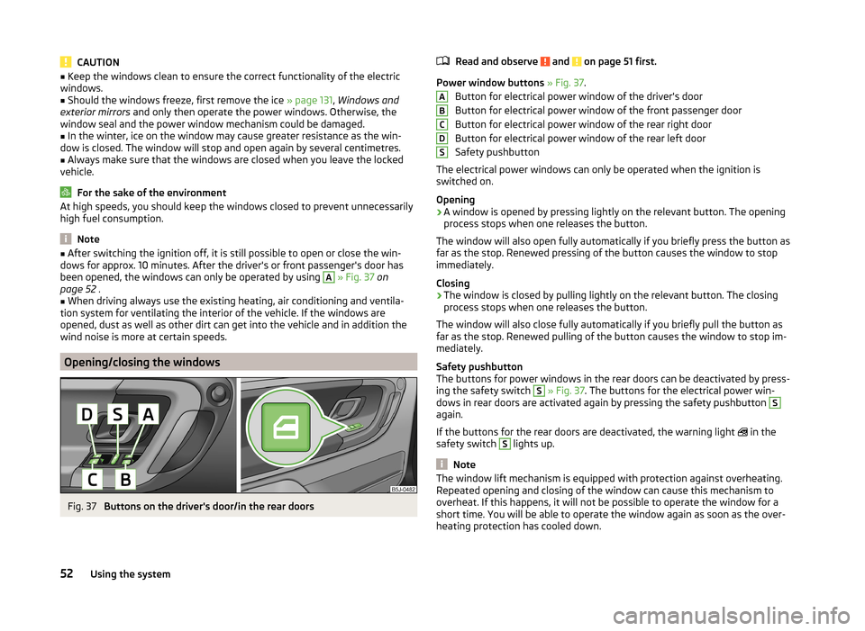
Power window buttons » Fig. 37 .
Button for electrical power window of the driver's door
Button for electrical power window of the front passenger door
Button for electrical power window of the rear right door
Button for electrical power window of the rear left door
Safety pushbutton
The electrical power windows can only be operated when the ignition is
switched on.
Opening
›
A window is opened by pressing lightly on the relevant button. The opening
process stops when one releases the button.
The window will also open fully automatically if you briefly press the button as
far as the stop. Renewed pressing of the button causes the window to stop
immediately.
Closing
›
The window is closed by pulling lightly on the relevant button. The closing
process stops when one releases the button.
The window will also close fully automatically if you briefly pull the button as
far as the stop. Renewed pulling of the button causes the window to stop im-
mediately.
Safety pushbutton
The buttons for power windows in the rear doors can be deactivated by press-
ing the safety switch
S
» Fig. 37 . The buttons for the electrical power win-
dows in rear doors are activated again by pressing the safety pushbutton
S
again.
If the buttons for the rear doors are deactivated, the warning light in the
safety switch
S
lights up.
Note
The window lift mechanism is equipped with protection against overheating.
Repeated opening and closing of the window can cause this mechanism to
overheat. If this happens, it will not be possible to operate the window for a
short time. You will be able to operate the window again as soon as the over-
heating protection has cooled down.ABCDS52Using the system
Page 106 of 197
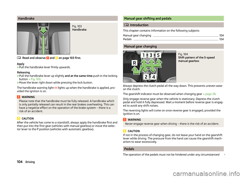
HandbrakeFig. 103
Handbrake
Read and observe and on page 103 first.
Apply
›
Pull the handbrake lever firmly upwards.
Releasing
›
Pull the handbrake lever up slightly and at the same time push in the locking
button » Fig. 103 .
›
Move the lever right down while pressing the lock button.
The handbrake warning light lights up when the handbrake is applied, pro-
vided the ignition is on.
WARNINGPlease note that the handbrake must be fully released. A handbrake which
is only partially released can result in the rear brakes overheating. This can
have a negative effect on the operation of the brake system – there is a
risk of an accident.
CAUTION
After the vehicle has come to a standstill, always apply the handbrake first and
then put into the first gear (vehicles with manual gearbox) or move the selec-
tor lever to the P position (vehicles with automatic gearbox).Manual gear shifting and pedals
Introduction
This chapter contains information on the following subjects:
Manual gear changing
104
Pedals
104
Manual gear changing
Fig. 104
Shift pattern of the 5-speed
manual gearbox
Always depress the clutch pedal all the way down. This prevents uneven wear on the clutch.
The gearshift indicator must be observed when changing gear » page 28.
Only engage reverse gear when the vehicle is stationary. Depress the clutch
pedal and hold it fully depressed. Wait a moment before reverse gear is engag-
ed to avoid any shift noises.
The reversing lights will come on once reverse gear is engaged, provided the
ignition is on.
WARNINGNever engage reverse gear when driving – there is the risk of an accident.
CAUTION
If not in the process of changing gear, do not leave your hand on the gearshift
lever while driving. The pressure from the hand can cause the gearshift mech-
anism to wear excessively.
Pedals
The operation of the pedals must not be hindered under any circumstances!
104Driving
Page 109 of 197
When accelerating, the gearbox automatically shifts up into the higher gear
just before the maximum permissible engine speed is reached.
If a lower gear is selected, the gearbox does not shift down until there is no risk of the engine overrevving.
Note
It may be advantageous to use manual gear shifting when driving downhill, for
example. Shifting to a lower gear reduces the load on the brakes and hence
brake wear » page 103, Information for braking .
Starting-off and driving
Read and observe
and on page 105 first.
Starting off
›
Start the engine.
›
Firmly depress and hold the brake pedal.
›
Press and hold the shiftlock button on the selector lever grip.
›
Move the selector lever into the desired position » page 105 and then release
the lock button.
›
Release the brake pedal and accelerate.
Stop
›
Fully depress and hold the brake pedal and bring the vehicle to a stop.
›
Keep holding the brake pedal until driving is resumed.
The selector lever position N does not have to be selected when stopping for a
short time, such as at a cross roads.
Parking
›
Fully depress and hold the brake pedal and bring the vehicle to a stop.
›
Firmly apply the handbrake.
›
Press and hold the shiftlock button on the selector lever grip.
›
Move the selector lever to the P position and then release the shiftlock but-
ton.
Kickdown
The kickdown function allows you to achieve maximum acceleration by your vehicle while driving.
When the accelerator pedal is fully depressed, the kickdown function is activa-
ted in any forward driving mode.
The gearbox shifts down one or more gears depending on the vehicle speed
and engine speed, and the vehicle accelerates.
The gearbox does not shift up into the highest gear until the engine has
reached its maximum revolutions for this gear range.WARNINGRapid acceleration, particularly on slippery roads, can lead to loss of control
of the vehicle – there is a risk of an accident.
Malfunction
Read and observe
and on page 105 first.
Emergency programme
The transmission switches to the emergency programme if there is a fault in
the automatic gearbox system.
Indications of an activated emergency programme include the following:
› Only certain gears are selected.
› Reverse gear
R cannot be used.
› Shifting gears in Tiptronic mode is not possible.
Gearbox overheating
The gearbox may, for example, become too hot due to frequent repeated
starting or stop-and-go traffic. Overheating is indicated by the warning
light » page 34 ,
Clutches of the automatic DSG gearbox are too hot
.
Note
Visit a specialist workshop if the gearbox has switched to the emergency pro-
gramme.107Starting-off and Driving
Page 127 of 197
On downhill sections shift down a gear in good time to also use the engine as
a brake.
Engine overheating
The speed must be reduced immediately if the needle for the coolant tempera-
ture gauge moves into the right-hand area or the red area of the scale.
Stop and switch off the engine if the warning light
in the instrument cluster
starts to flash. Wait a few minutes and check the level of coolant » page 144,
Checking the coolant level .
The following guidelines must be observed » page 37,
Coolant .
The coolant temperature can be reduced by switching on the heating.WARNING■ Adapt your speed to the conditions of the road surface and to the traffic
situation.■
Improper or incorrectly connected electric cables can energise the trailer
and cause functional faults to the vehicle's entire electrical system as well
as accidents and severe injuries.
■
Work on the electrical system must only be carried out by specialist ga-
rages.
■
Never directly connect the trailer's electrical system with the electrical
connections for the tail lights or other current sources.
Note
■ After coupling the trailer and connecting up the power socket, check the rear
lights on the trailer to ensure they work.■
If there is an error in the trailer lighting system, check the fuses in the fuse
box in the dashboard » page 168.
■
If you tow a trailer frequently, you should also have your car inspected be-
tween service intervals.
■
The handbrake on the towing vehicle must be applied when coupling and un-
coupling the trailer.
Anti-theft alarm system
Read and observe
on page 124 first.
When the vehicle is locked, the alarm is activated as soon as the electrical con-
nection to the trailer is interrupted.
Always switch off the anti-theft alarm system before a trailer is coupled or un-
coupled » page 49 .
Conditions for including a trailer in the anti-theft alarm system. The vehicle is factory-fitted with an anti-theft alarm system and towing
equipment.
The trailer is electrically connected to the towing vehicle by means of the
trailer socket.
The electrical system of the vehicle and trailer is functional.
The vehicle is locked with the vehicle key and the anti-theft alarm system is activated.
Note
For technical reasons, trailers with rear LED lights cannot be connected to the
anti-theft alarm system.125Towing a trailer
Page 145 of 197
We recommend maintaining the oil level within the range A, but not above , if
the engine has been operating at high loads, for example, during a lengthy
motorway trip during the summer months, towing a trailer or negotiating a
high mountain pass.
The warning light in the instrument cluster will indicate whether the oil level is
too low » page 36 ,
Engine oil . Check the oil level using the dipstick as
soon as possible. Add oil accordingly.
CAUTION
■ Always check the oil level on vehicles with the 1.2 l/44 kW engine when the
engine is cold. Otherwise the measuring result is incorrect und oil could be in-
correctly replenished - risk of engine damage!■
The oil level must never be above the
A
range » Fig. 128 – there is a risk of
damaging the exhaust system.
Replenishing
Read and observe
and on page 141 first.
›
Check the oil level » page 142.
›
Unscrew the cap of the engine oil filler opening » Fig. 126 on page 140 .
›
Replenish the oil in portions of 0.5 litres in accordance with the correct speci-
fications » page 141 .
›
Check the oil level » page 142.
›
Carefully screw on the oil filler opening cap and push the dipstick in fully.
Changing
Read and observe
and on page 141 first.
The engine oil must be changed according to prescribed service intervals or ac-cording to the » Service plan service interval display.
Coolant
Introduction
This chapter contains information on the following subjects:
Capacity
144
Checking the coolant level
144
Replenishing
144The coolant consists of water with a concentration of coolant additive. This mixture guarantees antifreeze protection, protects the cooling/heater system
against corrosion and prevents the formation of scale.
Vehicles exported to countries with a mild climate are already factory-filled
with a coolant which offers antifreeze protection down to about -25 ℃. In
these countries the concentration of coolant additive should be at least 40 %.
Vehicles exported to countries with a cold climate are already factory-filled
with a coolant which offers antifreeze protection down to about -35 °C. In
these countries the concentration of coolant additive should be at least 50 %.
If a higher concentration of antifreeze is required for climatic reasons, the
amount of coolant additive can only be increased up to a maximum of 60 %
(antifreeze protection down to approx. -40 °C).
When refilling, only use the same antifreeze identified on the coolant expan-
sion vessel » Fig. 129 on page 144 .WARNING■
The engine compartment of your car is a hazardous area. While working in
the engine compartment, be sure to observe the following warn-
ings » page 138 .■
Do not continue your journey if for some reason it is not possible to top
up the coolant under the current conditions. Switch off the engine and
seek assistance from a specialist garage.
CAUTION
■ The amount of coolant additive in the coolant must never be allowed to fall
below 40 %.■
Over 60 % coolant additive in the coolant reduces the antifreeze protection
and coolant effectiveness.
■
A coolant additive that does not comply with the correct specifications can
significantly reduce the corrosion protection.
■
Any faults resulting from corrosion may cause a loss of coolant and can con-
sequently result in major engine damage!
■
Do not fill the coolant above the mark
A
» Fig. 129 on page 144 .
■
We recommend that you visit a specialist garage if a fault causes the engine
to overheat, otherwise serious engine damage may occur.
■
Additional headlights and other attached components in front of the air inlet
impair the cooling efficiency of the coolant.
■
Never cover the radiator - there is a risk of the engine overheating.
143Inspecting and replenishing
Page 166 of 197
›Do not remove the foreign body, e.g. screw or nail, from the tyre.›Unscrew the valve cap.›
Use the valve remover
1
to unscrew the valve core and place it on a clean
surface (rag, paper, etc.).
Sealing and inflating the tyre
Read and observe
on page 163 first.
Sealing
›
Shake the tyre inflator bottle
10
» Fig. 145 on page 163 vigorously several
times.
›
Firmly screw the inflation hose
3
onto the tyre inflator bottle
10
in a clock-
wise direction. The film on the cap is pierced automatically.
›
Remove the plug from the inflation hose
3
and plug the open end fully onto
the tyre valve.
›
Hold the bottle
10
with the bottom facing upwards and fill all of the sealing
agent from the tyre inflator bottle into the tyre.
›
Remove the empty tyre inflator bottle from the valve.
›
Screw the valve core back into the tyre valve using the valve remover
1
.
Inflating
›
Screw the air compressor tyre inflation hose
5
» Fig. 145 on page 163 firmly
onto the tyre valve.
›
Check that the air release valve
7
is closed.
›
Start the engine and run it in idle.
›
Plug the connector
9
into 12 Volt socket » page 79, 12-volt power outlet .
›
Switch on the air compressor with the ON and OFF switch
8
.
›
Allow the air compressor to run until a pressure of 2.0 - 2.5 bar is achieved.
Maximum run time of 8 minutes » .
›
Switch off the air compressor.
›
If you cannot reach an air pressure of 2.0 – 2.5 bar, unscrew the tyre inflation
hose
5
from the tyre valve.
›
Drive the vehicle 10 metres forwards or backwards to allow the sealing agent
to “distribute” in the tyre.
›
Firmly screw the tyre inflation hose
5
back onto the tyre valve and repeat
the inflation process.
›
If you cannot reach the required tyre inflation pressure here either, this
means the tyre has sustained too much damage. You cannot seal with tyre with the breakdown kit »
.
›
Switch off the air compressor.
›
Remove the tyre inflation hose
5
from the tyre valve.
Once a tyre pressure of 2.0 – 2.5 bar is reached, the journey may be continued
at a maximum speed of 80 km/h (50 mph).
Check the tyre inflation pressure after driving for 10 minutes » page 164.WARNING■
The tyre inflation hose and air compressor may get hot as the tyre is be-
ing inflated – there is a risk of injury.■
Do not place the hot tyre inflation hose or hot air compressor on flamma-
ble materials – there is a risk of fire.
■
If you cannot inflate the tyre to at least 2.0 bar, this means the damage
sustained was too serious. The sealing agent cannot be used to seal the
tyre.
Do not drive the vehicle. Seek help from a specialist garage.
CAUTION
Switch off the air compressor after running 8 minutes at the latest – there is a
risk of overheating. Allow the air compressor to cool a few minutes before
switching it on again.
Check after 10 minutes' driving
Read and observe
on page 163 first.
Check the tyre inflation pressure after driving for 10 minutes!
If the tyre pressure is 1.3 bar or less
›
Do not drive the vehicle. You cannot properly seal with tyre with the
breakdown kit.
If the tyre pressure is 1.3 bar or more
›
Adjust the tyre pressure to the correct value again (see inside of fuel filler
cap).
›
Continue driving carefully to the nearest specialist garage at a maximum speed of 80 km/h (50 mph).
Jump-starting
Introduction
This chapter contains information on the following subjects:
Jump-starting using the battery from another vehicle
165
Jump-starting in vehicles with the START-STOP system
166
164Do-it-yourself