brake light SKODA KODIAQ 2016 1.G Owner's Guide
[x] Cancel search | Manufacturer: SKODA, Model Year: 2016, Model line: KODIAQ, Model: SKODA KODIAQ 2016 1.GPages: 344, PDF Size: 58.96 MB
Page 252 of 344
Pedestrian recognitionRead and observe
and on page 248 first.
The pedestrian recognition can help to prevent accidents with crossing pedes-trians or to mitigate the consequences of an accident.
The system warns of an imminent collision, prepares the vehicle for an emer-
gency braking, supports during braking or performs an automatic braking.
Emergency braking at low speed
If there is a risk of collision in a vehicle speed range of about 5 km/h to 30
km/h, the system triggers an automatic braking.
With automatic braking, the warning light appears in the display
» Fig. 310
on page 249 .
Advance warning and automatic braking
If the system detects a risk of collision in a vehicle speed range of 30 km / h to 65 km / h, the warning light appears on the display
» Fig. 310 on page 249
and an audible signal is emitted.
With a warning the brake pedal must be pressed or the moving obstacle is to
be avoided!
If the driver does not respond to the advance warning, the system begins to
automatically brake the vehicle.
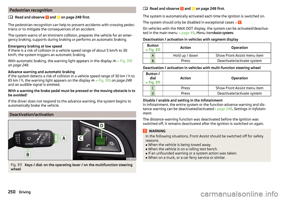
Deactivation/activation
Fig. 311
Keys / dial: on the operating lever / on the multifunction steering
wheel
Read and observe and on page 248 first.
The system is automatically activated each time the ignition is switched on.
The system should only be disabled in exceptional cases »
.
On vehicles with the MAXI DOT display, the system can be activated/deactiva- ted in the main menu » page 49, Menu item
Assist systems
.
Deactivation / activation in vehicles with segment display
Button
» Fig. 311ActionOperationAHold up / downShow Front Assist menu itemBPressDeactivate/activate system
Deactivation / activation in vehicles with multi-function steering wheel
Button / dial
» Fig. 311ActionOperation
CPressShow Front Assist menu itemDPressDeactivate/activate system
Disable / enable and setting in the Infotainment
In Infotainment, the entire system or the function advance warning and dis-
tance warning can be deactivated/activated » page 248, Settings in Infotain-
ment .
The distance-warning function was deactivated before the ignition was
switched off, it remains deactivated after the ignition is switched on again.
WARNINGIn the following situations, Front Assist should be switched off for safety
reasons.■
When the vehicle is being towed away.
■
When the vehicle is on a rolling test bench.
■
If an unfounded warning or a system action was taken.
■
When on a truck, or a car ferry service or similar.
250Driving
Page 267 of 344
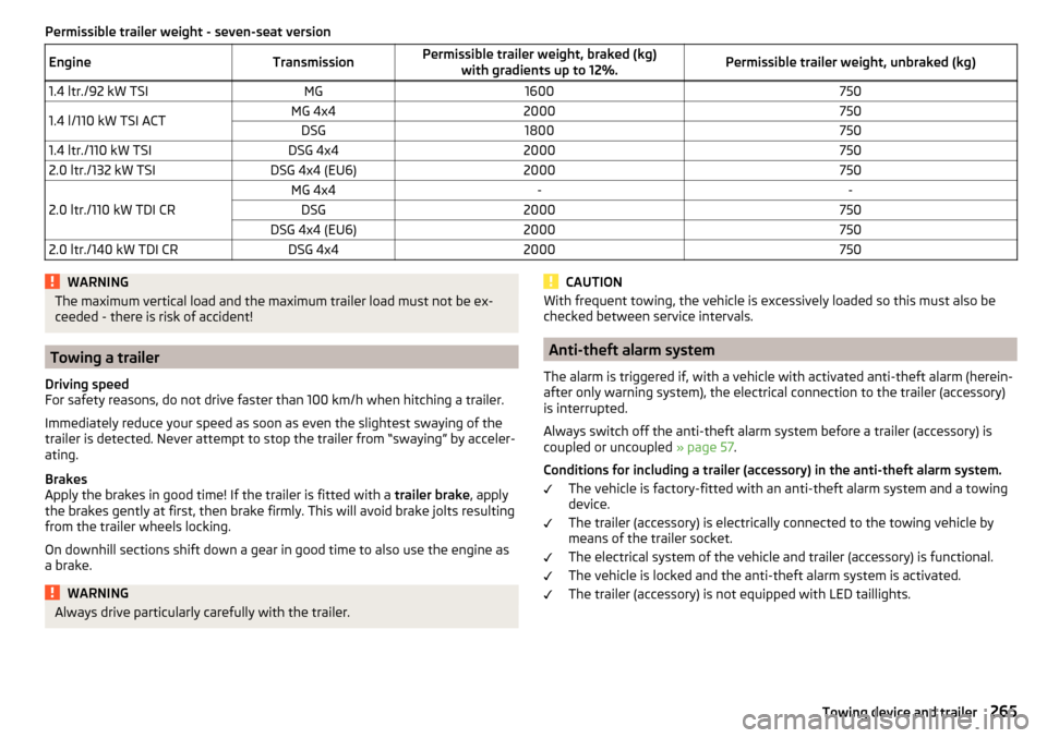
Permissible trailer weight - seven-seat versionEngineTransmissionPermissible trailer weight, braked (kg)with gradients up to 12%.Permissible trailer weight, unbraked (kg)1.4 ltr./92 kW TSIMG16007501.4 l/110 kW TSI ACTMG 4x42000750DSG18007501.4 ltr./110 kW TSIDSG 4x420007502.0 ltr./132 kW TSIDSG 4x4 (EU6)2000750
2.0 ltr./110 kW TDI CR
MG 4x4--DSG2000750DSG 4x4 (EU6)20007502.0 ltr./140 kW TDI CRDSG 4x42000750WARNINGThe maximum vertical load and the maximum trailer load must not be ex-
ceeded - there is risk of accident!
Towing a trailer
Driving speed
For safety reasons, do not drive faster than 100 km/h when hitching a trailer.
Immediately reduce your speed as soon as even the slightest swaying of the
trailer is detected. Never attempt to stop the trailer from “swaying” by acceler-
ating.
Brakes
Apply the brakes in good time! If the trailer is fitted with a trailer brake, apply
the brakes gently at first, then brake firmly. This will avoid brake jolts resulting
from the trailer wheels locking.
On downhill sections shift down a gear in good time to also use the engine as
a brake.
WARNINGAlways drive particularly carefully with the trailer.CAUTIONWith frequent towing, the vehicle is excessively loaded so this must also be
checked between service intervals.
Anti-theft alarm system
The alarm is triggered if, with a vehicle with activated anti-theft alarm (herein-
after only warning system), the electrical connection to the trailer (accessory)
is interrupted.
Always switch off the anti-theft alarm system before a trailer (accessory) is
coupled or uncoupled » page 57.
Conditions for including a trailer (accessory) in the anti-theft alarm system. The vehicle is factory-fitted with an anti-theft alarm system and a towing
device.
The trailer (accessory) is electrically connected to the towing vehicle by
means of the trailer socket.
The electrical system of the vehicle and trailer (accessory) is functional.
The vehicle is locked and the anti-theft alarm system is activated.
The trailer (accessory) is not equipped with LED taillights.
265Towing device and trailer
Page 281 of 344
CAUTIONRefill only operating fluids of the correct specification - danger of damaging
the vehicle!
Note
■ Fluids with the proper specifications can be purchased from the ŠKODA Origi-
nal Accessories or from the ŠKODA Genuine Parts ranges.■
We recommend you have the battery replaced by a specialist garage.
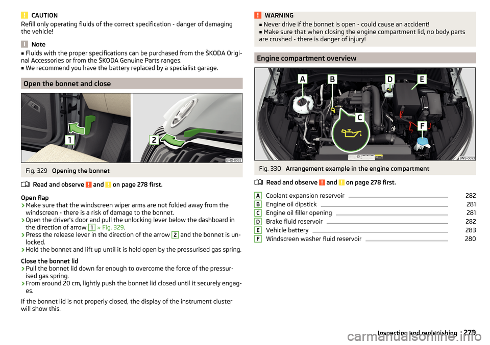
Open the bonnet and close
Fig. 329
Opening the bonnet
Read and observe
and on page 278 first.
Open flap
›
Make sure that the windscreen wiper arms are not folded away from the
windscreen - there is a risk of damage to the bonnet.
›
Open the driver's door and pull the unlocking lever below the dashboard in
the direction of arrow
1
» Fig. 329 .
›
Press the release lever in the direction of the arrow
2
and the bonnet is un-
locked.
›
Hold the bonnet and lift up until it is held open by the pressurised gas spring.
Close the bonnet lid
›
Pull the bonnet lid down far enough to overcome the force of the pressur-
ised gas spring.
›
From around 20 cm, lightly push the bonnet lid closed until it securely engag-
es.
If the bonnet lid is not properly closed, the display of the instrument cluster
will show this.
WARNING■ Never drive if the bonnet is open - could cause an accident!■Make sure that when closing the engine compartment lid, no body parts
are crushed - there is danger of injury!
Engine compartment overview
Fig. 330
Arrangement example in the engine compartment
Read and observe
and on page 278 first.
Coolant expansion reservoir
282
Engine oil dipstick
281
Engine oil filler opening
281
Brake fluid reservoir
282
Vehicle battery
283
Windscreen washer fluid reservoir
280ABCDEF279Inspecting and replenishing
Page 284 of 344
CAUTIONDo not cover the radiator or fit any parts (e.g. auxiliary lights) in front of the air
intakes - there is a risk of the engine overheating.
Checking and refilling
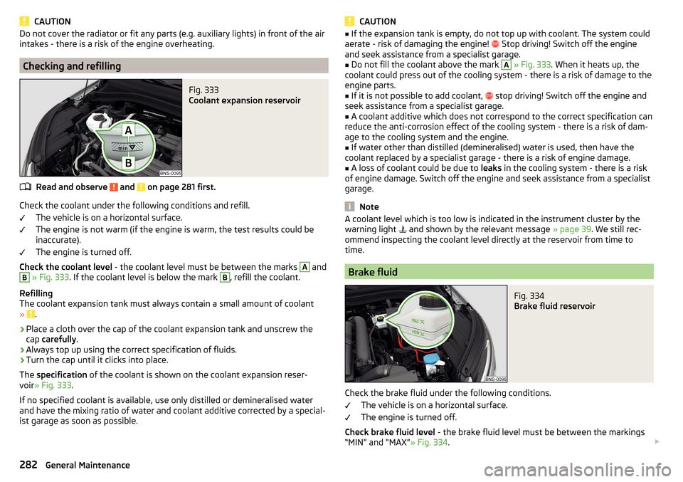
Fig. 333
Coolant expansion reservoir
Read and observe and on page 281 first.
Check the coolant under the following conditions and refill.
The vehicle is on a horizontal surface.
The engine is not warm (if the engine is warm, the test results could be
inaccurate).
The engine is turned off.
Check the coolant level - the coolant level must be between the marks
A
and
B
» Fig. 333 . If the coolant level is below the mark
B
, refill the coolant.
Refilling
The coolant expansion tank must always contain a small amount of coolant
»
.
›
Place a cloth over the cap of the coolant expansion tank and unscrew the
cap carefully .
›
Always top up using the correct specification of fluids.
›
Turn the cap until it clicks into place.
The specification of the coolant is shown on the coolant expansion reser-
voir » Fig. 333 .
If no specified coolant is available, use only distilled or demineralised water
and have the mixing ratio of water and coolant additive corrected by a special-
ist garage as soon as possible.
CAUTION■ If the expansion tank is empty, do not top up with coolant. The system could
aerate - risk of damaging the engine! Stop driving! Switch off the engine
and seek assistance from a specialist garage.■
Do not fill the coolant above the mark
A
» Fig. 333 . When it heats up, the
coolant could press out of the cooling system - there is a risk of damage to the
engine parts.
■
If it is not possible to add coolant,
stop driving! Switch off the engine and
seek assistance from a specialist garage.
■
A coolant additive which does not correspond to the correct specification can
reduce the anti-corrosion effect of the cooling system - there is a risk of dam-
age to the cooling system and the engine.
■
If water other than distilled (demineralised) water is used, then have the
coolant replaced by a specialist garage - there is a risk of engine damage.
■
A loss of coolant could be due to leaks in the cooling system - there is a risk
of engine damage. Switch off the engine and seek assistance from a specialist
garage.
Note
A coolant level which is too low is indicated in the instrument cluster by the
warning light and shown by the relevant message » page 39. We still rec-
ommend inspecting the coolant level directly at the reservoir from time to
time.
Brake fluid
Fig. 334
Brake fluid reservoir
Check the brake fluid under the following conditions.
The vehicle is on a horizontal surface.
The engine is turned off.
Check brake fluid level - the brake fluid level must be between the markings
“MIN” and “MAX” » Fig. 334.
282General Maintenance
Page 285 of 344
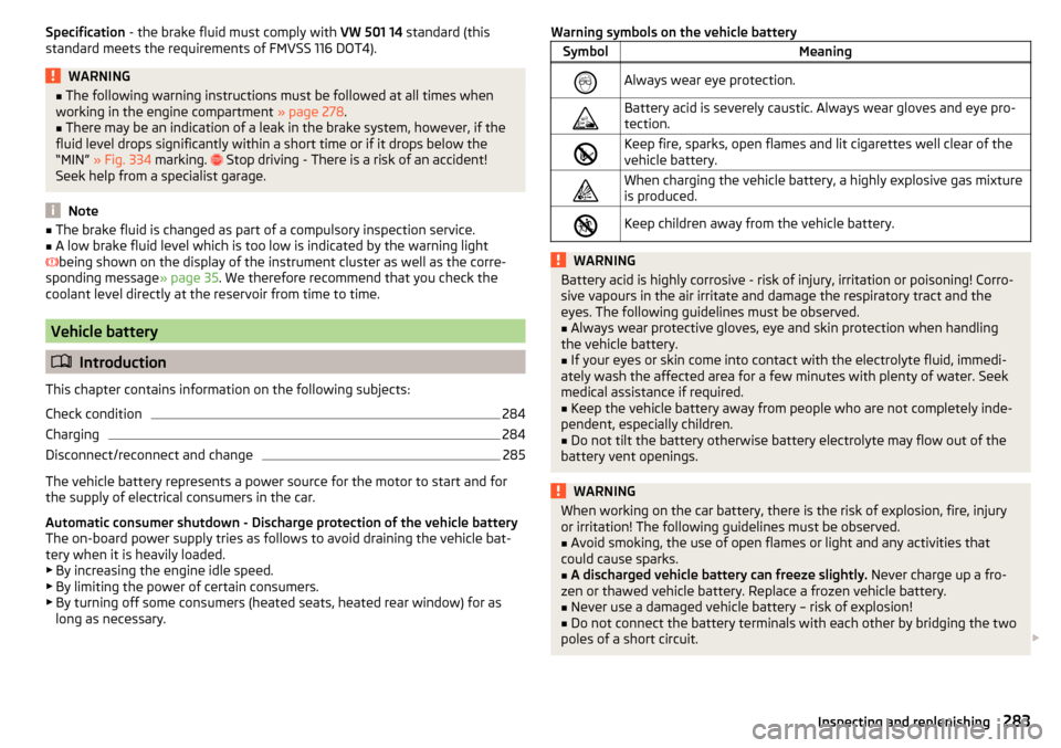
Specification - the brake fluid must comply with VW 501 14 standard (this
standard meets the requirements of FMVSS 116 DOT4).WARNING■ The following warning instructions must be followed at all times when
working in the engine compartment » page 278.■
There may be an indication of a leak in the brake system, however, if the
fluid level drops significantly within a short time or if it drops below the
“MIN” » Fig. 334 marking.
Stop driving - There is a risk of an accident!
Seek help from a specialist garage.
Note
■ The brake fluid is changed as part of a compulsory inspection service.■A low brake fluid level which is too low is indicated by the warning light
being shown on the display of the instrument cluster as well as the corre-
sponding message » page 35. We therefore recommend that you check the
coolant level directly at the reservoir from time to time.
Vehicle battery
Introduction
This chapter contains information on the following subjects:
Check condition
284
Charging
284
Disconnect/reconnect and change
285
The vehicle battery represents a power source for the motor to start and for the supply of electrical consumers in the car.
Automatic consumer shutdown - Discharge protection of the vehicle battery
The on-board power supply tries as follows to avoid draining the vehicle bat-
tery when it is heavily loaded.
▶ By increasing the engine idle speed.
▶ By limiting the power of certain consumers.
▶ By turning off some consumers (heated seats, heated rear window) for as
long as necessary.
Warning symbols on the vehicle batterySymbolMeaningAlways wear eye protection.Battery acid is severely caustic. Always wear gloves and eye pro-
tection.Keep fire, sparks, open flames and lit cigarettes well clear of the
vehicle battery.When charging the vehicle battery, a highly explosive gas mixture
is produced.Keep children away from the vehicle battery.WARNINGBattery acid is highly corrosive - risk of injury, irritation or poisoning! Corro-
sive vapours in the air irritate and damage the respiratory tract and the
eyes. The following guidelines must be observed.■
Always wear protective gloves, eye and skin protection when handling
the vehicle battery.
■
If your eyes or skin come into contact with the electrolyte fluid, immedi-
ately wash the affected area for a few minutes with plenty of water. Seek
medical assistance if required.
■
Keep the vehicle battery away from people who are not completely inde-
pendent, especially children.
■
Do not tilt the battery otherwise battery electrolyte may flow out of the
battery vent openings.
WARNINGWhen working on the car battery, there is the risk of explosion, fire, injury
or irritation! The following guidelines must be observed.■
Avoid smoking, the use of open flames or light and any activities that
could cause sparks.
■
A discharged vehicle battery can freeze slightly. Never charge up a fro-
zen or thawed vehicle battery. Replace a frozen vehicle battery.
■
Never use a damaged vehicle battery – risk of explosion!
■
Do not connect the battery terminals with each other by bridging the two
poles of a short circuit.
283Inspecting and replenishing
Page 301 of 344
Conditions for towing.Cars with automatic gearboxes must not be towed with the rear wheels
raised - there is a risk of gearbox damage!
If the gearbox has no oil, your vehicle must be towed with the front axle
raised clear of the ground or on a breakdown vehicle or trailer.
The maximum towing speed is 50 km/h.
The vehicle must be transported on a special breakdown vehicle or trailer
if it is not possible to tow in the vehicle in the way described or if the tow-
ing distance is greater than 50 km.
Driver of the tow vehicle›
On vehicles with manual transmission , engage gear slowly when starting.
›
On vehicles with automatic transmission , accelerate with particular care.
›
Only then approach correctly when the rope is taut.
Driver of the towed vehicle
›
If possible, the vehicle should be towed with the engine running. Operate the
brake booster and power steering only if the engine is running, otherwise
the brake pedal must be depressed more strongly and more power has to be
directed to the steering.
›
If it is not possible to start the engine, switch on the ignition so that the
steering wheel is not locked and so that the turn signal lights, windscreen
wipers and windscreen washer system can be used.
›
Take the vehicle out of gear or move the selector lever into position N if the
vehicle is fitted with an automatic gearbox.
›
Always keep the tow rope taut during the towing procedure.
WARNING■ Wound tow ropes must not be used for towing » Fig. 351- , the towing
eye may unscrew out of the vehicle - risk of accident.■
Ensure tow rope is not twisted - risk of accident.
CAUTION
■ Do not tow-start the engine – risk of damaging the engine! The battery from
another vehicle can be used as a jump-start aid » page 297, Jump-starting .■
In the case of off-road towing manoeuvres, for both vehicles there is the risk
that the fastening parts could be overloaded and damaged.
Note
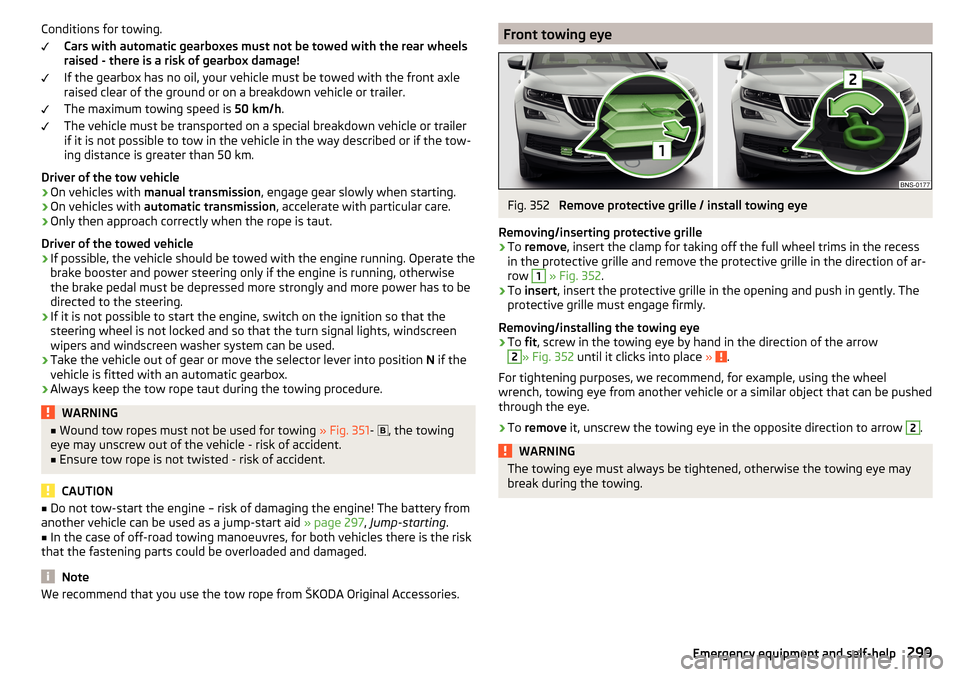
We recommend that you use the tow rope from ŠKODA Original Accessories.Front towing eyeFig. 352
Remove protective grille / install towing eye
Removing/inserting protective grille
›
To remove , insert the clamp for taking off the full wheel trims in the recess
in the protective grille and remove the protective grille in the direction of ar-
row
1
» Fig. 352 .
›
To insert , insert the protective grille in the opening and push in gently. The
protective grille must engage firmly.
Removing/installing the towing eye
›
To fit, screw in the towing eye by hand in the direction of the arrow
2
» Fig. 352 until it clicks into place » .
For tightening purposes, we recommend, for example, using the wheel
wrench, towing eye from another vehicle or a similar object that can be pushed through the eye.
›
To remove it, unscrew the towing eye in the opposite direction to arrow
2
.
WARNINGThe towing eye must always be tightened, otherwise the towing eye may
break during the towing.299Emergency equipment and self-help
Page 308 of 344
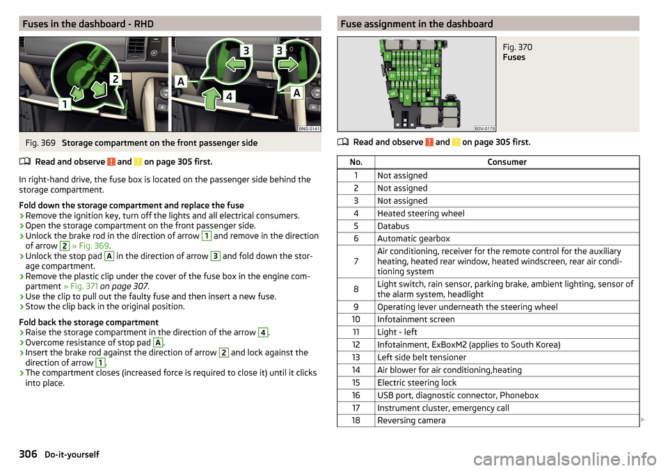
Fuses in the dashboard - RHDFig. 369
Storage compartment on the front passenger side
Read and observe
and on page 305 first.
In right-hand drive, the fuse box is located on the passenger side behind the storage compartment.
Fold down the storage compartment and replace the fuse
›
Remove the ignition key, turn off the lights and all electrical consumers.
›
Open the storage compartment on the front passenger side.
›
Unlock the brake rod in the direction of arrow
1
and remove in the direction
of arrow
2
» Fig. 369 .
›
Unlock the stop pad
A
in the direction of arrow
3
and fold down the stor-
age compartment.
›
Remove the plastic clip under the cover of the fuse box in the engine com-
partment » Fig. 371 on page 307 .
›
Use the clip to pull out the faulty fuse and then insert a new fuse.
›
Stow the clip back in the original position.
Fold back the storage compartment
›
Raise the storage compartment in the direction of the arrow
4
.
›
Overcome resistance of stop pad
A
.
›
Insert the brake rod against the direction of arrow
2
and lock against the
direction of arrow
1
.
›
The compartment closes (increased force is required to close it) until it clicks
into place.
Fuse assignment in the dashboardFig. 370
Fuses
Read and observe and on page 305 first.
No.Consumer1Not assigned2Not assigned3Not assigned4Heated steering wheel5Databus6Automatic gearbox7Air conditioning, receiver for the remote control for the auxiliary
heating, heated rear window, heated windscreen, rear air condi-
tioning system8Light switch, rain sensor, parking brake, ambient lighting, sensor of
the alarm system, headlight9Operating lever underneath the steering wheel10Infotainment screen11Light - left12Infotainment, ExBoxM2 (applies to South Korea)13Left side belt tensioner14Air blower for air conditioning,heating15Electric steering lock16USB port, diagnostic connector, Phonebox17Instrument cluster, emergency call18Reversing camera 306Do-it-yourself
Page 309 of 344
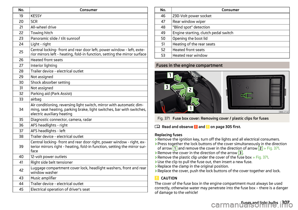
No.Consumer19KESSY20SCR21All-wheel drive22Towing hitch23Panoramic slide / tilt sunroof24Light - right25Central locking- front and rear door left, power window - left, exte-
rior mirrors left - heating, fold-in function, setting the mirror surface26Heated front seats27Interior lighting28Trailer device - electrical outlet29Not assigned30Shock absorber setting31Not assigned32Parking aid (Park Assist)33airbag34Air conditioning, reversing light switch, mirror with automatic dim-
ming, seat heating, parking brake, light switches, bar with switches,
electric auxiliary heating35Diagnostic connector, camera, radar36AFS headlights - right37AFS headlights - left38Trailer device - electrical outlet39Central locking- front and rear door right, power window - right, ex-
terior mirrors right - heating, fold-in function, setting the mirror sur-
face4012-volt power outlets41Right side belt tensioner42Luggage compartment cover lock, headlight washers, front and rear
window washer43Music amplifier44Trailer device - electrical outlet45Electrical operation of driver's seatNo.Consumer46230-Volt power socket47Rear window wiper48“Blind spot” detection49Engine starting, clutch pedal switch50Opening the boot lid51Heating of the rear seats52Heated front seats53Heated rear window
Fuses in the engine compartment
Fig. 371
Fuse box cover: Removing cover / plastic clips for fuses
Read and observe
and on page 305 first.
Replacing fuses
›
Remove the ignition key, turn off the lights and all electrical consumers.
›
Press together the lock buttons of the cover simultaneously in the direction
of arrow
1
and remove the cover in the direction of arrow
2
» Fig. 371 .
›
Remove the cover in the direction of the arrow
3
.
›
Remove the plastic clip under the cover of the fuse box » Fig. 371.
›
Use the clip to pull the fuse out, then insert a new fuse.
›
Replace the clamp in the original position.
›
Replace the cover, push the lock buttons of the cover together and lock.
CAUTION
The cover of the fuse box in the engine compartment must always be used
correctly, otherwise water may penetrate into the fuse box – there is a danger
of damage to the vehicle!307Fuses and light bulbs
Page 310 of 344
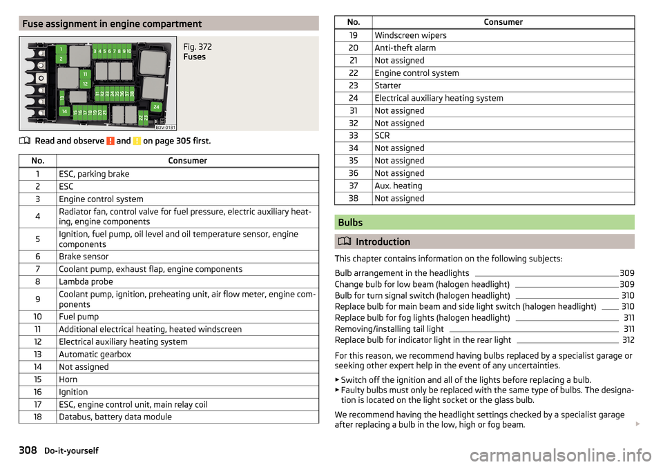
Fuse assignment in engine compartmentFig. 372
Fuses
Read and observe and on page 305 first.
No.Consumer1ESC, parking brake2ESC3Engine control system4Radiator fan, control valve for fuel pressure, electric auxiliary heat-
ing, engine components5Ignition, fuel pump, oil level and oil temperature sensor, engine
components6Brake sensor7Coolant pump, exhaust flap, engine components8Lambda probe9Coolant pump, ignition, preheating unit, air flow meter, engine com-
ponents10Fuel pump11Additional electrical heating, heated windscreen12Electrical auxiliary heating system13Automatic gearbox14Not assigned15Horn16Ignition17ESC, engine control unit, main relay coil18Databus, battery data moduleNo.Consumer19Windscreen wipers20Anti-theft alarm21Not assigned22Engine control system23Starter24Electrical auxiliary heating system31Not assigned32Not assigned33SCR34Not assigned35Not assigned36Not assigned37Aux. heating38Not assigned
Bulbs
Introduction
This chapter contains information on the following subjects:
Bulb arrangement in the headlights
309
Change bulb for low beam (halogen headlight)
309
Bulb for turn signal switch (halogen headlight)
310
Replace bulb for main beam and side light switch (halogen headlight)
310
Replace bulb for fog lights (halogen headlight)
311
Removing/installing tail light
311
Replace bulb for indicator light in the rear light
312
For this reason, we recommend having bulbs replaced by a specialist garage or
seeking other expert help in the event of any uncertainties.
▶ Switch off the ignition and all of the lights before replacing a bulb.
▶ Faulty bulbs must only be replaced with the same type of bulbs. The designa-
tion is located on the light socket or the glass bulb.
We recommend having the headlight settings checked by a specialist garage
after replacing a bulb in the low, high or fog beam.
308Do-it-yourself
Page 324 of 344
Manual shifting on the multifunction steeringwheel211
Selector lever lock210
Start and drive211
Tiptronic211
Warning light39
Automatic switch-off of Infotainment125
Automatic transmission209
Selector lever emergency release303
AUX90, 148
Settings134
Auxiliary heating (auxiliary heating and ventila- tion)
114
In infotainment115
set to115
Auxiliary heating (heating and ventilation) Radio remote control
116
Avoiding damage to your vehicle213
B
Basstöner
130
Battery Changing batteries for the removable light
302
Changing in key300, 301
Replace the battery in the remote control in the auxiliary heating
301
Belts15
Belt tensioners18
reversible18
Blanket96
Bluetooth A2DP / AVRCP
132
Name132
on / off132
Paired external devices132
Profile160
rSAP163
Set139
set to132, 134
Set to132
Switch on/off139
Update129, 133
Updates139
Visibility132, 139
Bluetooth Player149
Bluetooth® update160
bolero external module
123
infotainment Description122
Bonnet279
Boot Class N1 vehicles
106
Boot lid59
Automatic locking59
Contactless open/close61
Open/close58, 60
See boot lid58
Boot lid contactless open/close61
Brake Assist (HBA)217
Brake booster206
Brake fluid282
Check282
specification282
Brake linings Warning light
38
Brake pads new
206
Brake pedal (automatic gearbox) Warning light
38
Brakes Brake booster
206
Brake fluid282
Braking and stabilisation systems215
Information on braking206
Parking brake206
Run in212
Warning light35
Brake system215
breakdown call118
Breakdown call164
Broadcasting141, 142
Bulbs Replacing
308
Buttons on the driver door Electric windows
62
C
Call list Call list
166
CAR201
Car battery Automatic consumer shutdown
283
Check condition284
Cover284
Disconnecting and reconnecting285
Replacing285
Winter operation284
Car care Exterior
273
Interior273
Car cleaning Exterior
273
Windscreens273
Car computer see multifunction display
46
Care and maintenance266
Care Connect118
breakdown call118
emergency call118
information call118
Cargo element105
Carrier108
Carstick171
CD147
cellphone Disclaimer
120
Central locking52
Problems57
Central locking button54
322Index