sensor SKODA OCTAVIA 2008 2.G / (1Z) User Guide
[x] Cancel search | Manufacturer: SKODA, Model Year: 2008, Model line: OCTAVIA, Model: SKODA OCTAVIA 2008 2.G / (1Z)Pages: 304, PDF Size: 17.69 MB
Page 75 of 304
Lights and Visibility
74
Adjusting the right-hand exterior mirror
– Turn the rotary knob to position
. The movement of the mirror
surface is identical to the mo vement of the rotary knob.
Switching off operating control
– Turn the rotary knob to position
.
Folding in both exterior mirrors
– Turn the rotary knob to position
.
Lowerable exterior mirror* with the aid of the key for remote control
– If all the windows are closed, press the unlock button on the remote control ⇒page 50, fig. 49 for approx. 2 seconds.
Tilting surface of front pa ssenger exterior mirror*
When the rotary knob is in position
⇒ page 73, fig. 74 and the reverse gear is
engaged, the surface of the mirror tilts down slightly. This provides an aid in seeing
the kerb of the pavement when parking the car.
The mirror returns back into its initial po sition, after the rotary knob is moved out
of the position
and put into another position or if the speed is more than 15 km/h.
Memory for exterior mirrors*
On vehicles fitted with a memory for the driver seat, the relevant setting of the exte-
rior mirror is also stored automatically when the seat position is stored ⇒page 77.
WARNING
•Convex (curved outward) or spherical (differently curved) exterior
mirrors increase the vision field. Th ey do, however, make objects appear
smaller in the mirror. These mirrors are only of limited use, therefore, for
estimating distances to the following vehicles.
•Use whenever possible the interior rear mirror, for estimating the
distances to the fo llowing vehicles.
Note
•If the exterior mirrors are folded in using the remote control* of the vehicle key,
these are folded back into the driving po sition after switching on the ignition.
•If the exterior mirrors are folded in using the rotary knob ⇒page 73, fig. 74 ,
they can only be folded back into th e driving position using the rotary knob.
•If the exterior mirrors were folded in using the remote control* of the vehicle
key and if the rotary knob was in the fold -in position before switching on the igni-
tion, the mirrors remain in the fold-in positi on the next time the ignition is switched
on. Folding back into the driving position is performed by actuating the rotary knob
in a different position from the fold-in position.
•Do not touch the surfaces of the exterior mirrors if the exterior mirror heater is
switched on.
•You can set the exterior mirrors by hand, if the power setting function fails at any
time by pressing on the ed ge of the mirror surface.
•Contact your specialist garage if a fault exists with the power setting of the exte-
rior mirrors.
Automatic dimming exterior mirror*
The exterior mirrors are dimmed together with the interior mirror. If the automatic
dimming is switched on, the mirror dims automatically depending on the light
striking the mirror from the rear.
When the interior lights are switched on or the reverse gear is engaged, the mirror
always moves back into the basic position (not dimmed).
Note
•Automatic mirror dimming operates only properly if the sun screen* for the rear
window is not in use or the light striking the rear of the interior rear-view mirror is
not affected by other objects.
•Do not affix any stickers in front of the li ght sensor, so that you do not impair the
automatic dimming function or put it out of operation.
A3
20A5Facelift.book Page 74 Saturday, September 6, 2008 2:13 PM
Page 117 of 304
Heating and air conditioning system
116
WARNING
•For your own safety and that of other road users, ensure that all the
windows are free of ice, snow and mistin g. Please familiarize yourself about
how to correctly operate th e heating and ventilation systems, how to demist
and defrost the windows, as well as with the cooling mode.
•You should not leave recirculated air mode on over a longer period of
time, as “stale” air may result in fatigue in the driver and occupants, divert
your attention and also cause the windows to mist up. The risk of having an
accident increases. Switch recirculated air mode off as soon as the windows
begin misting up.
Note
•If the cooling system has not been switched on for a lengthy period, odours may
be produced at the evaporator because of deposits. Switch the cooling system on
at least once a month for approximately 5 mi nutes at the highest blower stage - also
during the cold season of the year - in order to remove such odours. Also open a
window for a short time.
•We recommend that you do not smoke in the vehicle when the recirculating air
mode is operating since the smoke which is drawn at the evaporator from the inte-
rior of the vehicle forms deposits in the evaporator of the air conditioning system.
This produces a permanent odour when the air conditioning system is operating
which can only be eliminated through co nsiderable effort and expense (replace-
ment of compressor).
•The used air streams out through the air removal openings in the luggage
compartment.
•On vehicles equipped with a factory-fitted radio* or navigation*, the informa-
tion of the Climatronic is also shown on the display. You can switch off this function
for the Radio* - see operating instructions for radio. This function cannot be
switched off during Navigation*.
•Using the cooling economically ⇒page 114.
•Operational problems ⇒page 115.
Overview of the control elements
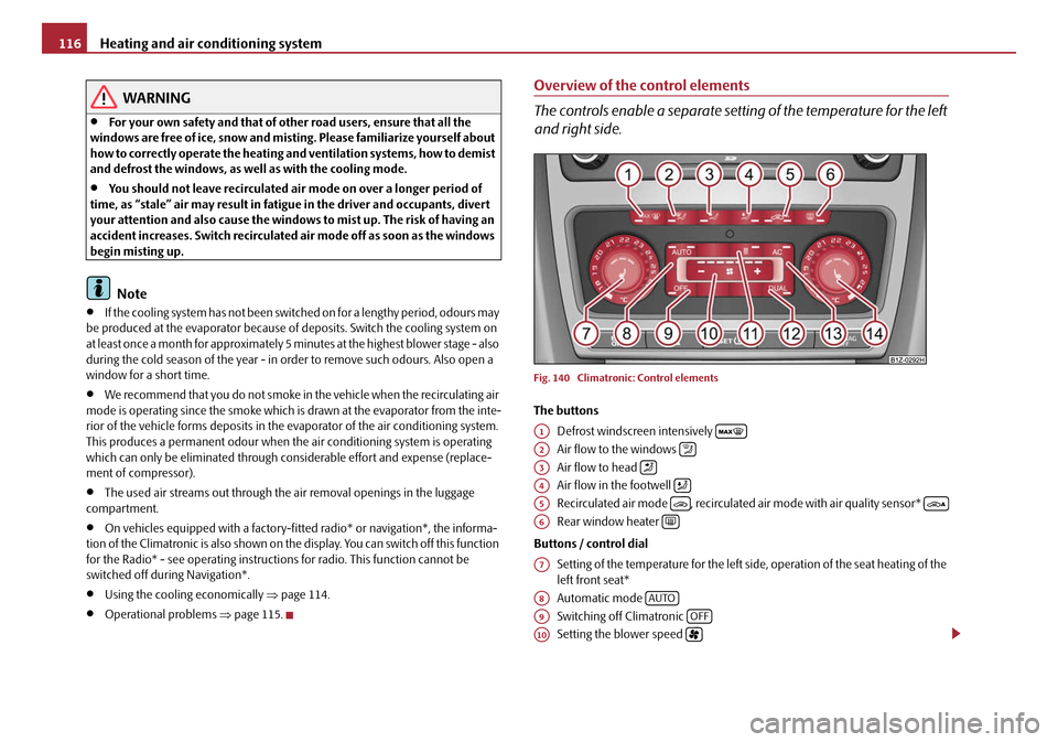
The controls enable a separate setting of the temperature for the left
and right side.
Fig. 140 Climatronic: Control elements
The buttons
Defrost windscreen intensively
Air flow to the windows
Air flow to head
Air flow in the footwell
Recirculated air mode , recirculated air mode with air quality sensor*
Rear window heater
Buttons / control dial Setting of the temperature for the left side, operation of the seat heating of the
left front seat*
Automatic mode
Switching off Climatronic
Setting the blower speed
A1
A2
A3
A4
A5
A6
A7
A8AUTO
A9OFF
A10
20A5Facelift.book Page 116 Saturday, September 6, 2008 2:13 PM
Page 118 of 304
Heating and air conditioning system117
Using the systemSafetyDriving TipsGeneral MaintenanceBreakdown assistanceTechnical Data
Button for direct switching on/off of au
xiliary heating (auxiliary heating)*
⇒ page 119
Switching on/off of the temperature setting in dual mode
Switching cooling on and off
Setting of the temperature for the right side, operation of the seat heating of
the right front seat*
Note
Below the top row of buttons is located the interior temperature sensor. Do not
glue or cover over the sensor, otherwise it could have an unfavourable effect on the
Climatronic.
Automatic mode
The automatic mode is used in order to maintain a constant temper-
ature and to demist the windows in the interior of the car.
Switching automatic mode on
– Set a temperature between +18 °C and +26 °C.
– Move the air outlet vents 3 and 4 ⇒ page 108, fig. 136 so that the air
flow is directed slightly upwards.
– Press the button . In the right or left top corner a warning light lights up, depending on which unit was last selected.
If the warning light in the top right corner of the button lights up, the
Climatronic operates in “HIGH” mode. The “HIGH” mode is the standard setting of
the Climatronic.
When pressing again the button , the Climatronic changes into the “LOW”
mode and the warning light in the top left corner lights up. The Climatronic uses
only in this mode the lower blower speed. However taking into account the noise
level, this is more comfortable, yet be aw are that the effectiveness of the air condi-
tioning system is reduced particularly if the vehicle is fully occupied.
By pressing again the button , yo u change into the “HIGH” mode. The automatic mode is switched off by pr
essing the button for the air distribution
or increasing or decreasing the blower speed. The temperature is nevertheless
regulated.
switching cooling on and off
switching cooling on and off
– Press the button ⇒ page 116, fig. 140. The warning light lights up
in the button.
– When you again press the switch , the cooling system is switched off. The warning light in the button goes out. Only the function of the
ventilation remains active when no lower temperature than the
outside temperature can be reached.
Setting temperature
You can separate the interior temperature for the left and right side sepa-
rately.
– You can set the temperature for both sides after switching on the igni- tion with the control dial .
– If you wish to set the temperature for the right side, turn the control dial . The warning light in the bu tton lights up, this indicates
that differing temperatures for the left and right side can be set.
If the warning light in the button lights up, the temperature for both sides
cannot be set with the control dial . You can reinitiate this function by pressing
the button . The warning light in the button which indicates the possibility to
set differing temperatures for the left and right side, goes out.
You can set the interior temperature be tween +18°C and +26°C. The interior
temperature is regulated automatically within this range. If you chose a tempera-
ture lower than +18°C, a blue symbol lights up at the start of the numerical scale. If
you chose a temperature higher than +26°C, a red symbol lights up at the end of
A11
A12DUAL
A13AC
A14
AUTO
AUTO
AUTO
AUTO
AC
AC
A7
A14DUAL
DUALA7DUAL
20A5Facelift.book Page 117 Saturday, September 6, 2008 2:13 PM
Page 119 of 304
Heating and air conditioning system
118
the numerical scale. In both limit positions the Climatronic operates at maximum
cooling or heating capacity, respectively. The temperature is not controlled in this
case.
Lengthy and uneven distribution of the air flow out of the vents (in particular at the
leg area) and large differences in temperature, for example when getting out of the
vehicle, can result in chills in sensitive persons.
Recirculated air mode
In recirculated air mode air is sucked out of the interior of the vehicle
and then fed back into the interior.
Recirculated air mode prevents polluted air outside the vehicle from
getting into the vehicle, for example when driving through a tunnel or
when standing in a traffic jam.
Switching recirculated air mode on
– Press the button - the warning light lights up in the button.
Switching recirculated air mode off
– Press again the button or the button - the warning light in
the button goes out.
WARNING
You should not leave recirculated air mode on over a longer period of time,
as “stale” air may result in fatigue in the driver and occupants, divert your
attention and also cause the windows to mist up. The risk of having an acci-
dent increases. Switch recirculated air mode off as soon as the windows
begin misting up.
Note
If the windscreen mists up, press the button ⇒page 116, fig. 140 . After
the windscreen has been demisted, press the button .
Automatic air distribution control
When the automatic air distribution control is switched on, an air
quality sensor measures the concentration of pollutants in the drawn
in air.
If a considerable increase in concentr ation of pollutants is recognized by
the air quality sensor, the air distribution control will temporarily be
switched off. If the concentration of pollutants decreases to the normal
level, the air distribution control is au tomatically switched off so that fresh
air can be guided into the vehicle interior.
Switch on automatic air distribution control
– Press the button repeatedly * until the warning light on the right side of the button lights up.
Switch off automatic air distribution control temporarily
– If the air quality sensor does not switch on automatically when there
is a nauseating smell, you can switch it on yourself by pressing the
button *. The warning light lights up in the button on the left side.
Switch on automatic air distribution control again
– Hold the button pressed * for more than 2 seconds and on the right side of the button the warning light lights up.
Switch off automatic air distribution control
– Press again the button * until the warning lights in the button go out.
WARNING
You should not leave recirculated air mode on over a longer period of time,
as “stale” air may result in fatigue in the driver and occupants, divert your
attention and also cause the windows to mist up. The risk of having an acci-
AUTO
A1AUTO
20A5Facelift.book Page 118 Saturday, September 6, 2008 2:13 PM
Page 130 of 304
Starting-off and Driving129
Using the systemSafetyDriving TipsGeneral MaintenanceBreakdown assistanceTechnical Data
Rear parking aid*
The parking aid provides a warning of obstacles behind the vehicle.
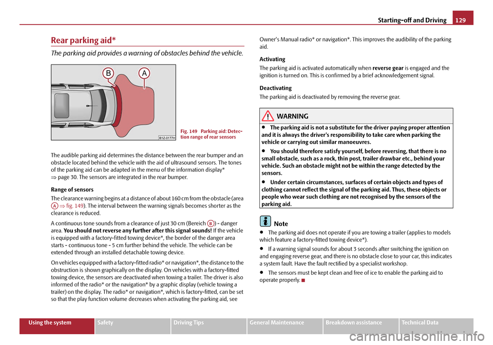
The audible parking aid determines the distance between the rear bumper and an
obstacle located behind the vehicle with the aid of ultrasound sensors. The tones
of the parking aid can be adapted in the menu of the information display*
⇒ page 30. The sensors are integrated in the rear bumper.
Range of sensors
The clearance warning begins at a distance of about 160 cm from the obstacle (area
⇒ fig. 149 ). The interval between the warning signals becomes shorter as the
clearance is reduced.
A continuous tone sounds from a clearanc e of just 30 cm (Bereich ) - danger
area. You should not reverse any further after this signal sounds! If the vehicle
is equipped with a factory-fi tted towing device*, the border of the danger area
starts - continuous tone - 5 cm further behind the vehicle. The vehicle can be
extended through an installe d detachable towing device.
On vehicles equipped with a factory-fitted radio* or navigation*, the distance to the
obstruction is shown graphically on the disp lay. On vehicles with a factory-fitted
towing device, the sensors are deactivated when towing a trailer. The driver is also
informed of the radio* or the navigation* by a graphic display (vehicle towing a
trailer) on the display. The radio* or navi gation*, which is factory-fitted, can be set
so that the play function volume decrea ses when activating the parking aid, see Owner's Manual radio* or navigation*. This improves the audibility of the parking
aid.
Activating
The parking aid is activated automatically when
reverse gear is engaged and the
ignition is turned on. This is conf irmed by a brief acknowledgement signal.
Deactivating
The parking aid is deactivated by removing the reverse gear.
WARNING
•The parking aid is not a substitute for the driver paying proper attention
and it is always the driver's responsibility to take care when parking the
vehicle or carrying ou t similar manoeuvres.
•You should therefore satisfy yourself, before reversing, that there is no
small obstacle, such as a rock, thin po st, trailer drawbar etc., behind your
vehicle. Such an obstacle might not be within the range detected by the
sensors.
•Under certain circumstances, surfaces of certain objects and types of
clothing cannot reflect the signal of the parking aid. Thus, these objects or
people who wear such clothing are not recognised by the sensors of the
parking aid.
Note
•The parking aid does not operate if you are towing a trailer (applies to models
which feature a factory-fi tted towing device*).
•If a warning signal sounds for about 3 seconds after switching the ignition on
and engaging reverse gear, and there is no obstacle close to your car, this indicates
a system fault. Have the fault rectified by a specialist workshop.
•The sensors must be kept clean and free of ice to enable the parking aid to
operate properly.
Fig. 149 Parking aid: Detec-
tion range of rear sensors
AA
AB
20A5Facelift.book Page 129 Saturday, September 6, 2008 2:13 PM
Page 131 of 304
Starting-off and Driving
130
Front and rear parking aid*
The parking aid provides a warning of obstacles in front and behind
the vehicle.
The audible parking aid determines the distance between the front or rear bumper
and an obstacle with the aid of ultrasound sensors. The sensors are integrated in the
front and rear bumper. The signal tones for the front parking aid sound higher as
standard than for the rear parking aid. The tones of the parking aid can be adapted
in the menu of the information display* ⇒page 30.
Range of sensors
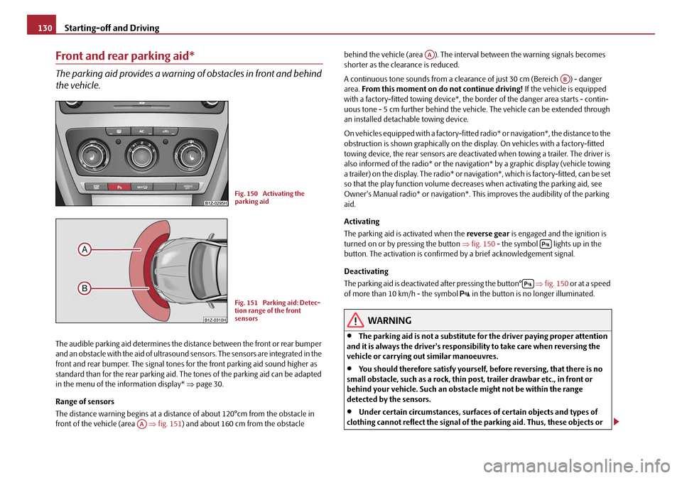
The distance warning begins at a distance of about 120°cm from the obstacle in
front of the vehicle (area ⇒fig. 151 ) and about 160 cm from the obstacle behind the vehicle (area ). The interv
al between the warning signals becomes
shorter as the clearance is reduced.
A continuous tone sounds from a clearanc e of just 30 cm (Bereich ) - danger
area. From this moment on do not continue driving! If the vehicle is equipped
with a factory-fitted towing device*, the bo rder of the danger area starts - contin-
uous tone - 5 cm further behind the vehicle. The vehicle can be extended through
an installed detachable towing device.
On vehicles equipped with a fa ctory-fitted radio* or navigation*, the distance to the
obstruction is shown graphically on the di splay. On vehicles with a factory-fitted
towing device, the rear sensors are deactivated when towing a trailer. The driver is
also informed of the radio* or the navigation* by a graphic display (vehicle towing
a trailer) on the display. The radio* or navi gation*, which is factory-fitted, can be set
so that the play function volume decreases when activating the parking aid, see
Owner's Manual radio* or navigation*. Th is improves the audibility of the parking
aid.
Activating
The parking aid is activated when the reverse gear is engaged and the ignition is
turned on or by pressing the button ⇒fig. 150 - the symbol lights up in the
button. The activation is confirmed by a brief acknowledgement signal.
Deactivating
The parking aid is deactivated after pressing the button° ⇒fig. 150 or at a speed
of more than 10 km/h - the symbol
in the button is no longer illuminated.
WARNING
•The parking aid is not a substitute fo r the driver paying proper attention
and it is always the driver's responsibility to take care when reversing the
vehicle or carrying out similar manoeuvres.
•You should therefore satisfy yourself, before reversing, that there is no
small obstacle, such as a rock, thin po st, trailer drawbar etc., in front or
behind your vehicle. Such an obstacle might not be within the range
detected by the sensors.
•Under certain circumstances, surfaces of certain objects and types of
clothing cannot reflect the signal of the parking aid. Thus, these objects or
Fig. 150 Activating the
parking aid
Fig. 151 Parking aid: Detec-
tion range of the front
sensors
AA
AA
AB
20A5Facelift.book Page 130 Saturday, September 6, 2008 2:13 PM
Page 132 of 304
Starting-off and Driving131
Using the systemSafetyDriving TipsGeneral MaintenanceBreakdown assistanceTechnical Data
people who wear such clothing are not recognised by the sensors of the
parking aid.
Note
•Only the front parking aid operates if you are towing a trailer (applies only to
models which feature a factory-fitted towing device*).
•If a warning signal sounds for about 3 seconds after activating the system and
there is no obstacle close to your car, th is indicates a system fault. The fault is
confirmed additionally when the symbol flashes in the button ⇒page 130,
fig. 150 . Have the fault rectified by a specialist workshop.
•The sensors must be kept clean and free of ice to enable the parking aid to
operate properly.
•If the parking aid is activated and the se lector lever of the automatic gearbox is
in the position , warning signal indicates interruption (vehicle can no longer
move).
Cruise control system (CCS)*
Introduction
The cruise control system (CCS) maintains a constant speed, more than 30 km/h (20
mph), once it has been set, without you having to depress the accelerator pedal.
This is only possible within the range which is permitted by the power output and
braking power of the engine. The cruise co ntrol system makes it possible - particu-
larly on long journeys - for you to rest your “accelerator foot”.
WARNING
•The cruise control system must not, for safety reasons, be used in dense
traffic or on unfavourable road surfaces (such as icy roads, slippery roads or
loose chippings) - risk of accident!
•In order to prevent unintentional use of the cruise control system, always
switch off the system after use.
Note
•Models fitted with a manual gearbox: Al ways depress the clutch pedal if you
switch on the cruise control system when the gearbox is in Neutral. Otherwise the
engine can rev up unintentionally.
•The cruise control system is not able to maintain a constant speed when driving
on steep downhill sections. The weight of the vehicle increases the speed at which
it travels. One should shift down in good time to a lower gear or slow the vehicle
down by applying the foot brake.
•It is not possible on vehicles fitted with an automatic gearbox to switch on the
cruise control system if the sele ctor lever is in the position P, N or R.
Storing a speed
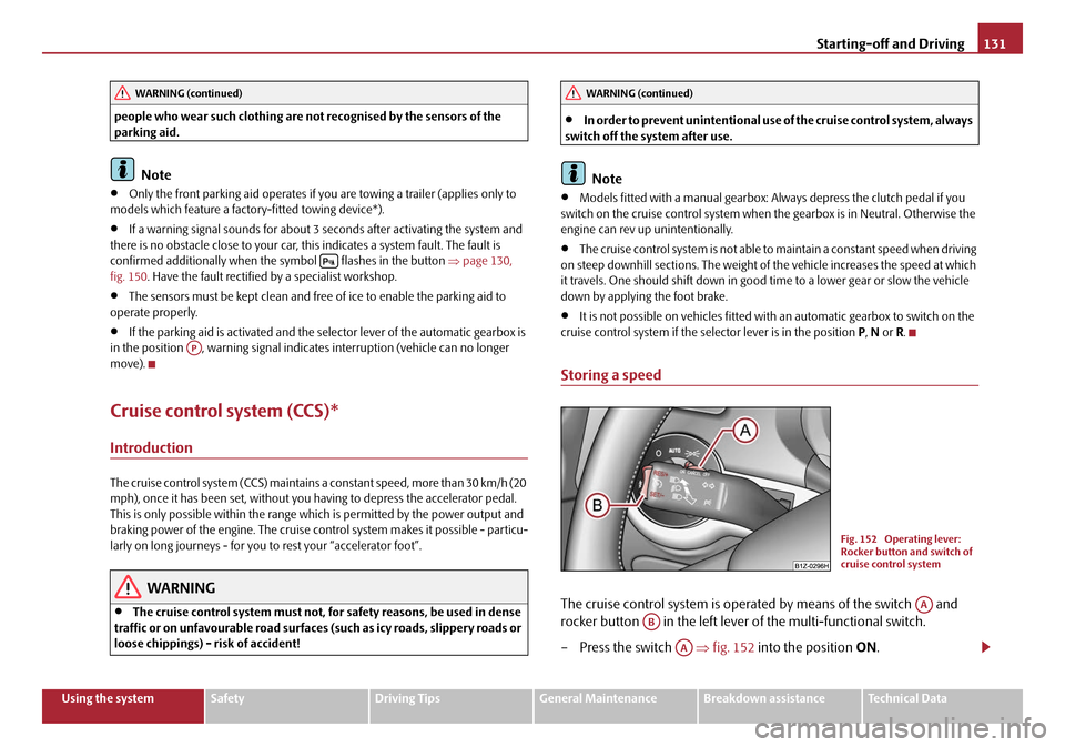
The cruise control system is operat ed by means of the switch and
rocker button in the left lever of the multi-functional switch.
– Press the switch ⇒fig. 152 into the position ON.
WARNING (continued)
AP
WARNING (continued)
Fig. 152 Operating lever:
Rocker button and switch of
cruise control system
AA
AB
AA
20A5Facelift.book Page 131 Saturday, September 6, 2008 2:13 PM
Page 180 of 304

Airbag system179
Using the systemSafetyDriving TipsGeneral MaintenanceBreakdown assistanceTechnical Data
Important safety information on the side airbag
Correct use of the airbag system considerably reduces the risk of
injury!
WARNING
•It is essential to always switch off ⇒page 181, “Deactivating an airbag”
the front passenger airbag when attach ing a child safety seat on the front
passenger seat where the child is seated with its back facing in direction of
travel (in some countries also when the ch ild is facing the direction of travel).
If this is not done, there is a risk of the child suffering severe or even fatal
injuries if the front passenger airbag is deployed. In certain countries
national legal provisions also requir e that the side or head passenger
airbags be deactivated. When transporting a child on the front passenger
seat, please comply with the appropri ate national regulations regarding the
use of child safety seats.
•Your head should never be positioned in the deployment area of the side
airbag. You might suffer severe injuries in the event of an accident. This
applies in particular to children who are transported without using a suit-
able child safety seat ⇒page 186, “Child safety and side airbag*”.
•If children adopt an incorrect seated position when travelling, they may
be exposed to an increased risk of injury in the event of an accident. This can
result in serious injuries ⇒page 184, “What you should know about trans-
porting children!”.
•There must not be any further persons, animals as well as objects posi-
tioned between the occupants and the de ployment area of the airbag. There
must also be no accessories such as cup holders, attached to the doors to
enable the side airbags to activate properly.
•The airbag control unit operates together with the pressure sensors,
which are attached in the front doors. For this reason no adjustments must
be carried out at the doors as well as at the door panels (for example addi-
tional installation of loudspeakers). Resulting damages can have a negative
affect on the operation of the airbag system. All work on the front doors and
their panels must only be carr ied out by a specialist garage.
•In the event of a side collision, the side airbags will not function properly,
if the sensors cannot measure the increa sing air pressure inside the doors,
because the air can escape through lar ge, non-sealed openings in the door
panel.
−Never drive with removed inner door panels.
− Never drive, if parts of the inner door panel have been removed and
the remaining openings have not been properly sealed.
− Never drive, if the loudspeakers in the doors have been removed, only
if the loudspeaker openings have been properly sealed.
− Always make sure that the openings are covered or filled, if additional
loudspeakers or other equipment part s are installed in the inner door
panels.
− Always work with a Škoda dealer or have it carried out by a competent
specialist workshop.
•Only hang light items of clothing on the clothes hooks to the vehicle.
Never leave any heavy or sharp-edged objects in the pockets of the items of
clothing.
•Ensure that there are no excessive fo rces, such as violent knocks, kicks
etc., impact on the backrests of the seats otherwise the system may be
damaged. The side airbags would not be deployed in such a case!
•Any seat or protective covers which you fit to the driver or front
passenger seats must only be of the type expressly authorized by Škoda
Auto. In view of the fact that the airbag inflates out of the backrest of the
seat, use of non-approved seat or protective covers would considerably
impair the protective function of the side airbag.
•Any damage to the original seat covers in the area of the side airbag
module must be repaired without delay by your specialist garage.
•The airbag modules in the front se ats must not display any damage,
cracks or deep scratches. It is not permissible to use force in order to open
the modules.
WARNING (continued)
20A5Facelift.book Page 179 Saturday, September 6, 2008 2:13 PM
Page 182 of 304

Airbag system181
Using the systemSafetyDriving TipsGeneral MaintenanceBreakdown assistanceTechnical Data
In certain accident si
tuations, the front, side and he ad airbag are simultaneously
deployed.
The airbags inflate in fractions of a second and at a high speed in order to be able
to offer that additional protection in th e event of an accident. A grey white, non
harmful gas is released when airbag is inflated. This is perfectly normal and is not
an indication of a fire in the vehicle.
Important safety information on the head airbag
Correct use of the airbag system considerably reduces the risk of
injury!
WARNING
•It is essential to always switch off ⇒page 181, “Deactivating an airbag”
the front passenger airbag when attach ing a child safety seat on the front
passenger seat where the child is seated with its back facing in direction of
travel (in some countries also when the ch ild is facing the direction of travel).
If this is not done, there is a risk of the child suffering severe or even fatal
injuries if the front passenger airbag is deployed. In certain countries
national legal provisions also requir e that the side or head passenger
airbags be deactivated. When transporting a child on the front passenger
seat, please comply with the appropri ate national regulations regarding the
use of child safety seats.
•There must not be any objects in the deployment area of the head
airbags which might prevent the ai rbags from inflating properly.
•Only hang light items of clothing on the clothes hooks to the vehicle.
Never leave any heavy or sharp-edged objects in the pockets of the items of
clothing. In addition, it is not permitted to use clothes hangers for hanging
up items of clothing.
•The airbag control unit operates together with the sensors, which are
attached in the front doors. For this reason no adjustments must be carried
out at the doors as well as at the door panels (for example additional instal-
lation of loudspeakers). Resulting dama ges can have a negative affect on the
operation of the airbag system. All work on the front doors and their panels
must only be carried ou t by a specialist garage.
•There must not be any other persons (e.g. children) or animals between
the car occupant and the deployment ar ea of the head airbag. In addition,
none of the occupants should lean their head out of the window when
driving, or extend their arms and hands out of the window.
•The sun visors must not be swivelled to the side windows into the
deployment area of the head airbags if any objects, such as ball-point pens
etc. are attached to them. This might resu lt in injuries to the occupants if the
head airbag is deployed.
•Installing impermissible accessories in the area of the head airbags may
considerably impair the protection offered by the head airbag in the event of
it being deployed. When the deployed he ad airbag is inflated, parts of the
accessories fitted may in certain circum stances be thrown into the interior
of the car and cause injuries to the occupants ⇒page 243, “Accessories,
changes and replacement of parts”.
•Any work on the head airbag system including installing and removing
system components because of other repair work (e.g. removing headliner)
must only be carried out by a specialist garage.
Deactivating an airbag
Deactivating airbags
If any airbags have been deactivated, switch them on again as soon
as possible so that they are able to again provide their proper protec-
tion.
There is the technical means installed within your vehicle to switch off the front,
side* or head airbag* (take out of commission).
This is why you should have the deacti vation of the airbags carried out by a
specialist garage.
On vehicles equipped with the switch for de activation of the airbags, you can deac-
tivate the front and side passenger airbag by means of this switch ⇒page 182.
WARNING (continued)
20A5Facelift.book Page 181 Saturday, September 6, 2008 2:13 PM
Page 194 of 304
Intelligent Technology193
Using the systemSafetyDriving TipsGeneral MaintenanceBreakdown assistanceTechnical Data
Driving Tips
Intelligent Technology
Electronic stability programme (ESP)*
General
General
The ESP aids you maintain control of your vehicle in situations in borderline driving
situations such as when negotiating a curve too fast. The risk of skidding is reduced
and your car thus offers greater driving stability depending on the conditions of the
road surface. This occurs at all speeds.
The following systems are integrated into the electronic stability programme:
•Electronic Differential Lock (EDL),
•Traction control system (TCS),
•Driver-steering recommendation,
•Antilock brake system (ABS),
•Brake Assist,
•Uphill-Start off-Assist. Operating principle
The ESP switches on automatically when the engine is started and then conducts a
self-test. The ESP control unit processes data from the individual systems. It also
processes additional measurement data which are supplied by highly sensitive
sensors: the rotational velocity of the vehi
cle about its vertical axis, the lateral accel-
eration of the vehicle, the brakin g pressure and the steering angle.
The direction which the driver wishes to ta ke is determined based on the steering
angle and the speed of the vehicle and is constantly compared with the actual
behaviour of the vehicle. If differences exis t, such as the car beginning to skid, the
ESP will automatically brake the appropriate wheel.
The car is stabilised again by the forces which take effect when the wheel is braked.
Intervention into the brake system takes place primarily on the outer front wheel of
a vehicle which tends to oversteer (tendency for the rear of the vehicle to break
away) while occurs this is on the inner re ar wheel of a vehicle which tends to under-
steer (tendency to shift out of the curve). This braking control cycle is accompanied
by noises.
The ESP operates in combination with the ABS ⇒page 197, “Antilock brake system
(ABS)”. If there is a fault in the ABS system, the ESP also does not operate.
The ESP warning light lights up in the instru ment cluster when there is a fault on the
ESP
⇒ page 38.
Switching off
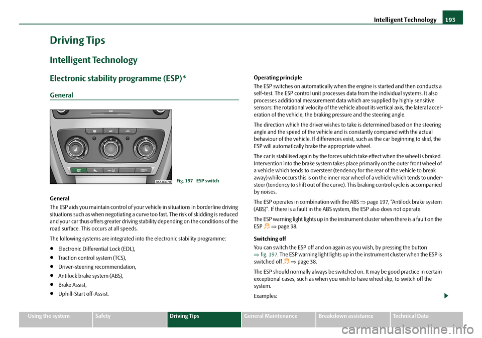
You can switch the ESP off and on again as you wish, by pressing the button
⇒ fig. 197 . The ESP warning light lights up in th e instrument cluster when the ESP is
switched off
⇒ page 38.
The ESP should normally always be switched on. It may be good practice in certain
exceptional cases, such as when you wish to have wheel slip, to switch off the
system.
Examples:
Fig. 197 ESP switch
20A5Facelift.book Page 193 Saturday, September 6, 2008 2:13 PM