ignition SKODA OCTAVIA 2013 3.G / (5E) Service Manual
[x] Cancel search | Manufacturer: SKODA, Model Year: 2013, Model line: OCTAVIA, Model: SKODA OCTAVIA 2013 3.G / (5E)Pages: 287, PDF Size: 18.55 MB
Page 77 of 287

›Hold the
rear head restraints on the sides with both hands and move them up-
wards » Fig. 49 .›
To move the head restraint downwards , press and hold the safety button
1
with one hand and press the head restraint downwards with the other hand.
The head restraints and the front seats must be adjusted to match the body size at all times and the seat belt must always be fastened properly to provide the
most effective levels of protection to the passengers » page 177, Correct seated
position .
Removing/installing
Only the real head restraints may be removed.
›
Pull the head restraint out of the seat backrest as far as the stop.
›
Press the locking button in the direction of arrow
1
» Fig. 49 simultaneously
press the locking button into the opening
2
using a flat screwdriver with a
width of maximum 5 mm and pull out the head rest.
›
To re-insert the head restraint, push it far enough down into the seat backrest until the locking button clicks into place.
WARNING■ The head restraints must be correctly adjusted in order to offer effective
protection for the occupants in the event of an accident.■
Never drive with the head restraints removed - risk of injury.
■
If the rear seats are occupied, the respective rear head restraint must not be
in the lower position.
Note
■ For the sports seats, the head restraints are integrated into the front seat
backrests. These headrests cannot be adjusted by height or removed.■
The middle rear head restraint is only adjustable in two positions.
Memory function of the electrically adjustable seatFig. 50
Memory buttons and SET button
First read and observe the introductory information and safety warn-
ings on page 71.
The memory function for the driver's seat provides the option to store the posi-
tions of the driver's seat and the external mirrors. Each of the three memory but- tons
B
» Fig. 50 can be assigned a set position.
Storing seat and exterior mirror settings for driving forward
›
Switch on the ignition.
›
Adjust the seat to the desired position.
›
Adjust both of the exterior mirrors » page 69.
›
Press the button SET
A
» Fig. 50 .
›
Within 10 seconds after pressing the SET button, press the desired memory
button
B
.
An acknowledgment sound confirms the storage.
Saving front passenger mirror settings when reversing
›
Switch on the ignition.
›
Press the required memory button
B
» Fig. 50 .
›
Adjust the rotary knob for the mirrors to the position
or in right-hand drive to
the position
» page 69 .
›
Engage reverse gear.
›
Adjust the front passenger's mirror to the desired position » page 69.
›
Disengage reverse gear.
The set position of the exterior mirror is stored.
Retrieving the saved setting
›
Tap the desired memory button
B
» Fig. 50 when the ignition is switched off
and the driver's door is opened.
74Using the system
Page 78 of 287
or›
Press down on the desired memory button
B
when the ignition is switched on
and the driver's door is closed.
Stopping the ongoing adjustment
›
Press any button on the driver's seat or the button on the remote control
key.
Note
Each time you store the seat and exterior mirror settings for driving forward you
also have to re-store the setting of the exterior mirror on the passenger side for
reversing.
Memory function of the remote control key
First read and observe the introductory information and safety warn-ings
on page 71.
The automatic storage of the driver's seat and exterior mirror positions when
locking the vehicle can be turned on in the memory of the remote control key (af-
terwards only as function of automatic storage).
This function can also be activated or deactivated in the Infotainment » Bedie-
nungsanleitung Infotainment, chapter Vehicle settings (CAR button)..
Storing seat and exterior mirror settings for driving forward
›
Enable automatic storage.
When automatic storage is activated, the current positions of the driver's seat
and the external mirrors are saved in the memory of the remote control key each
time the vehicle is locked. When the vehicle is next unlocked using the same key,
the driver's seat and the external mirrors assume the positions stored in the
memory of this key 1)
.
Saving front passenger mirror settings when reversing
›
Unlock the vehicle with the remote control key.
›
Switch on the ignition.
›
Adjust the rotary knob for the mirrors to the position
or in right-hand drive to
the position
» page 69 .
›Engage reverse gear.›Adjust the front passenger's mirror to the desired position
» page 69.›
Disengage reverse gear.
The adjusted position of the exterior mirror is stored in the remote control key
memory.
Enable automatic storage
›
Unlock the vehicle with the remote control key.
›
Press and hold any memory button
B
» Fig. 50 on page 74. After the seat has
assumed the position stored under this button, at the same time press the but-
ton
on the remote control key within 10 seconds.
The successful activation of the automatic storage function for each key is con-
firmed by an acoustic signal.
The seat and exterior mirror settings are not saved in the memory of the key,
which is already saved in the memory button.
The seat can be adjusted to the required position if necessary » page 73.
After locking the vehicle, the current positions of the driver's seat and the exter-
nal mirrors are saved in the memory of the remote control key.
Disable the function of automatic storage
›
Unlock the vehicle with the remote control key.
›
Press and hold the SET button
A
» Fig. 50 on page 74. At the same time, press
the button on the remote control key within 10 seconds.
The successful deactivation of the automatic storage function for each key is con-
firmed by an acoustic signal.
Stopping the ongoing adjustment
›
Press any button on the driver's seat or the button on the remote control
key.
1)
The vehicle must be locked and unlocked with the same key to save the seat and exterior mirror po-
sition to the key.
75Seats and useful equipment
Page 86 of 287
WARNING■Never put hot beverage containers in the cup holder. If the vehicle moves,
they may spill – risk of scalding!■
Do not use any cups or beakers which are made of brittle material (e.g. glass,
porcelain). This could lead to injuries in the event of an accident.
CAUTION
Do not leave open beverage containers in the cup holder during the journey.
There is a risk of spilling e.g. when braking which may cause damage to the elec-
trical components or seat upholstery.
Cigarette lighter
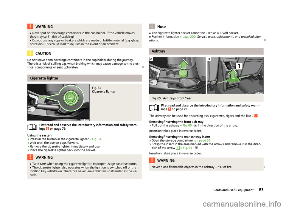
Fig. 64
Cigarette lighter
First read and observe the introductory information and safety warn-
ings on page 79.
Using the system
›
Press in the button in the cigarette lighter » Fig. 64
.
›
Wait until the button pops forward.
›
Remove the cigarette lighter immediately and use.
›
Place the cigarette lighter back into the socket.
WARNING■
Take care when using the cigarette lighter! Improper usage can case burns.■The cigarette lighter also operates when the ignition is switched off or the
ignition key withdrawn. Therefore never leave children unattended in the ve-
hicle.Note■ The cigarette lighter socket cannot be used as a 12Volt socket.■Further information » page 200, Service work, adjustments and technical alter-
ations .
Ashtray
Fig. 65
Ashtrays: front/rear
First read and observe the introductory information and safety warn- ings
on page 79.
The ashtray can be used for discarding ash, cigarettes, cigars and the like » .
Removing/inserting the front ash tray
›
Pull out the ashtray » Fig. 65 -
in the direction of the arrow.
Insertion takes place in reverse order.
Removing/inserting the rear ashtray insert
›
Open the storage compartment » page 88
.
›
Grasp the insert in the area marked with the arrows and remove it in the direc-
tion of the arrow
1
» Fig. 65 -
.
Insertion takes place in reverse order.
WARNINGNever place flammable objects in the ashtray – risk of fire! 83Seats and useful equipment
Page 87 of 287
CAUTIONWhen removing do not hold the ashtray at the cover on the front – risk of break-
age.
12-volt power outlet
Fig. 66
12-Volt power socket: in the front centre console/ in the boot
First read and observe the introductory information and safety warn- ings
on page 79.
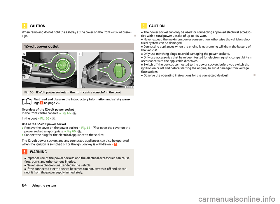
Overview of the 12-volt power socket
In the front centre console » Fig. 66 -
.
In the boot » Fig. 66 -
.
Use of the 12-volt power socket
›
Remove the cover on the power socket » Fig. 66 -
or open the cover on the
power socket as appropriate » Fig. 66 -
.
›
Connect the plug for the electrical appliance to the socket.
The 12-volt power sockets and any connected appliances can also be operated when the ignition is switched off or the ignition key is withdrawn »
.
WARNING■
Improper use of the power sockets and the electrical accessories can cause
fires, burns and other serious injuries.■
Never leave children unattended in the vehicle.
■
If the connected electric device becomes too hot, switch it off and discon-
nect it from the power supply immediately.
CAUTION■ The power socket can only be used for connecting approved electrical accesso-
ries with a total power uptake of up to 120 watt.■
Never exceed the maximum power consumption, otherwise the vehicle's elec-
trical system can be damaged.
■
Connecting appliances when the engine is not running will drain the battery of
the vehicle!
■
Only use matching plugs to avoid damaging the power sockets.
■
Only use accessories that have been tested for electromagnetic compatibility in
accordance with the applicable directives.
■
Switch off the devices connected to the power sockets before you switch the
ignition on or off and before starting the engine, to avoid damage from voltage
fluctuations.
■
Observe the operating instructions for the connected devices!
84Using the system
Page 92 of 287
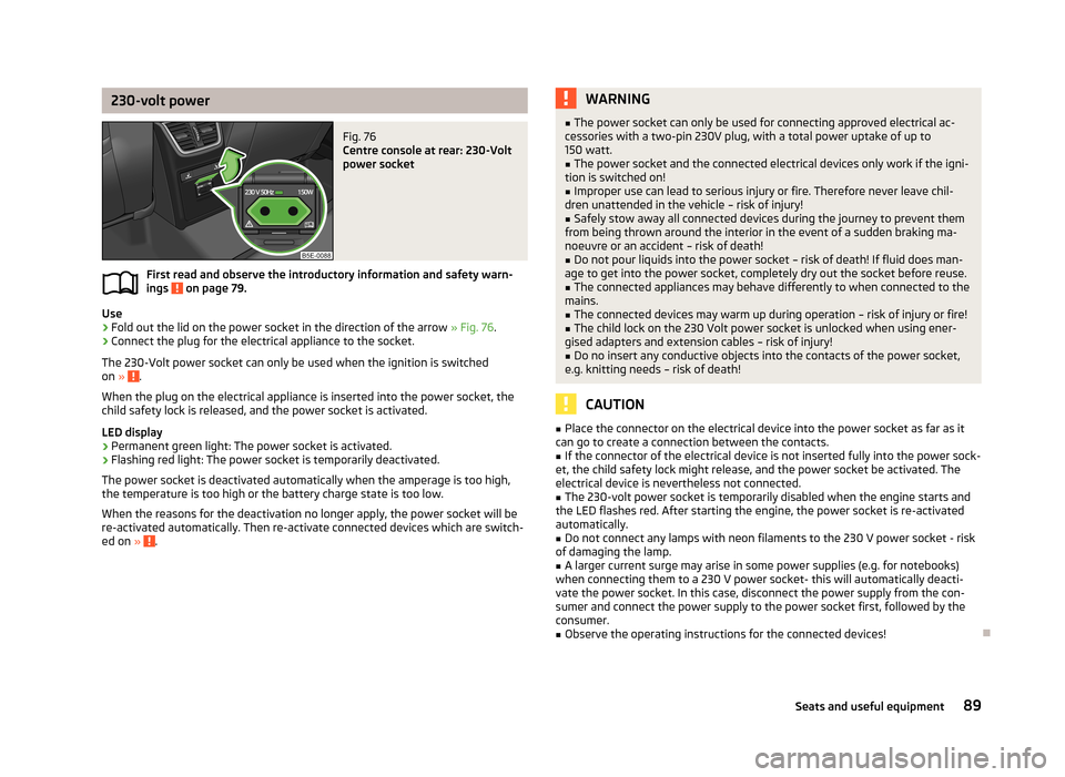
230-volt powerFig. 76
Centre console at rear: 230-Volt
power socket
First read and observe the introductory information and safety warn-
ings on page 79.
Use
›
Fold out the lid on the power socket in the direction of the arrow » Fig. 76.
›
Connect the plug for the electrical appliance to the socket.
The 230-Volt power socket can only be used when the ignition is switched on »
.
When the plug on the electrical appliance is inserted into the power socket, the
child safety lock is released, and the power socket is activated.
LED display › Permanent green light: The power socket is activated.
› Flashing red light: The power socket is temporarily deactivated.
The power socket is deactivated automatically when the amperage is too high, the temperature is too high or the battery charge state is too low.
When the reasons for the deactivation no longer apply, the power socket will be
re-activated automatically. Then re-activate connected devices which are switch-
ed on »
.
WARNING■
The power socket can only be used for connecting approved electrical ac-
cessories with a two-pin 230V plug, with a total power uptake of up to 150 watt.■
The power socket and the connected electrical devices only work if the igni-
tion is switched on!
■
Improper use can lead to serious injury or fire. Therefore never leave chil-
dren unattended in the vehicle – risk of injury!
■
Safely stow away all connected devices during the journey to prevent them
from being thrown around the interior in the event of a sudden braking ma- noeuvre or an accident – risk of death!
■
Do not pour liquids into the power socket – risk of death! If fluid does man-
age to get into the power socket, completely dry out the socket before reuse.
■
The connected appliances may behave differently to when connected to the
mains.
■
The connected devices may warm up during operation – risk of injury or fire!
■
The child lock on the 230 Volt power socket is unlocked when using ener-
gised adapters and extension cables – risk of injury!
■
Do no insert any conductive objects into the contacts of the power socket,
e.g. knitting needs – risk of death!
CAUTION
■ Place the connector on the electrical device into the power socket as far as it
can go to create a connection between the contacts.■
If the connector of the electrical device is not inserted fully into the power sock-
et, the child safety lock might release, and the power socket be activated. The
electrical device is nevertheless not connected.
■
The 230-volt power socket is temporarily disabled when the engine starts and
the LED flashes red. After starting the engine, the power socket is re-activated
automatically.
■
Do not connect any lamps with neon filaments to the 230 V power socket - risk
of damaging the lamp.
■
A larger current surge may arise in some power supplies (e.g. for notebooks)
when connecting them to a 230 V power socket- this will automatically deacti-
vate the power socket. In this case, disconnect the power supply from the con-
sumer and connect the power supply to the power socket first, followed by the
consumer.
■
Observe the operating instructions for the connected devices!
89Seats and useful equipment
Page 94 of 287
WARNING (Continued)■Make sure that the strap A holds the skis in front of the binding (also refer
to imprint on the removable through-loading bag).■
The total weight of the skis which are transported must not exceed 24 kg.
Note
■ The through-loading bag is foreseen for four pairs of skis.■Place the skis with the tips facing to the front and the sticks with the tips facing
to the rear. into the removable through-loading bag.■
If there are several pairs of skis in the removable through-loading bag, ensure
that the bindings are positioned at the same height.
■
The removable through-loading bag must never be folded together or stowed
when moist.
Luggage compartment
Introduction
This chapter contains information on the following subjects:
Class N1 vehicles
92
Fastening elements
92
Fixing nets
93
Folding double hooks
93
Foldable hooks (Octavia Estate)
94
Floor covering
94
Double sided floor covering
94
Luggage net
95
Luggage compartment cover
95
Roll-up luggage compartment cover (Octavia Estate)
96
Stowing roll-up luggage compartment cover and roof racks
97
Storage compartment in the luggage compartment
98
Storage compartments under the floor covering
98
Multifunction box (Octavia Estate)
99
Please observe the following for the purpose of maintaining good handling char-
acteristics of your vehicle:
› Distribute loads as evenly as possible.›Place heavy objects as far forward as possible.›
Attach the items of luggage to the lashing eyes or using the nets
» page 92.
In the event of an accident, even small and light objects gain so much kinetic en-
ergy that they can cause severe injuries.
The magnitude of the kinetic energy is dependent on the speed at which the ve-
hicle is travelling and the weight of the object.
Example: In the event of a frontal collision at a speed of 50 km/h, an object with a
weight of 4.5 kg produces an energy, which corresponds to 20 times its own
weight. This means that it results in a weight of approx. 90 kg “ ”.
Luggage compartment light
The light switches on/off when the boot lid is opened or closed.
If the boot lid is open and the ignition switched off, the light will extinguish auto-
matically after around 10 minutes.
WARNING■ Store the objects in the luggage compartment and attach them to the lash-
ing eyes.■
Loose objects can be thrown forward during a sudden manoeuvre or in case
of an accident and can injure the occupants or other road users.
■
Loose objects could hit a deployed airbag and injure occupants – danger of
death!
■
Please note that the handling properties of the vehicle may be affected
when transporting heavy objects as the centre of gravity can be displaced –
risk of accident! The speed and style of driving must be adjusted accordingly.
■
If the items of luggage or objects are attached to the lashing eyes with un-
suitable or damaged lashing straps, injuries can occur in the event of braking
manoeuvres or accidents. To prevent items of luggage from moving around,
always use suitable lashing straps which must be firmly attached to the lash-
ing eyes.
■
The items carried in the luggage compartment must be stored in such a way
that no objects are able to slip forward if any sudden driving or braking ma-
noeuvres are undertaken – risk of injury!
91Seats and useful equipment
Page 119 of 287
Switching on/offFig. 111
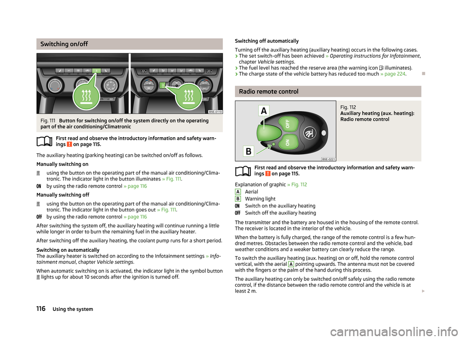
Button for switching on/off the system directly on the operating
part of the air conditioning/Climatronic
First read and observe the introductory information and safety warn-ings
on page 115.
The auxiliary heating (parking heating) can be switched on/off as follows.
Manually switching on using the button on the operating part of the manual air conditioning/Clima-
tronic. The indicator light in the button illuminates » Fig. 111.
by using the radio remote control » page 116
Manually switching off
using the button on the operating part of the manual air conditioning/Clima-
tronic. The indicator light in the button goes out » Fig. 111.
by using the radio remote control » page 116
After switching the system off, the auxiliary heating will continue running a little
while longer in order to burn the remaining fuel in the auxiliary heater.
After switching off the auxiliary heating, the coolant pump runs for a short period.
Switching on automatically
The auxiliary heater is switched on according to the Infotainment settings » Info-
tainment manual , chapter Vehicle settings .
When automatic switching on is activated, the indicator light in the symbol button lights up for about 10 seconds after the ignition is turned off.
Switching off automatically
Turning off the auxiliary heating (auxiliary heating) occurs in the following cases. › The set switch-off has been achieved
» Operating instructions for Infotainment ,
chapter Vehicle settings .
› The fuel level has reached the reserve area (the warning icon
illuminates).
› The charge state of the vehicle battery has reduced too much
» page 224.
Radio remote control
Fig. 112
Auxiliary heating (aux. heating):
Radio remote control
First read and observe the introductory information and safety warn-
ings on page 115.
Explanation of graphic » Fig. 112
Aerial
Warning light
Switch on the auxiliary heating
Switch off the auxiliary heating
The transmitter and the battery are housed in the housing of the remote control. The receiver is located in the interior of the vehicle.
When the battery is fully charged, the range of the remote control is a few hun-
dred metres. Obstacles between the radio remote control and the vehicle, bad
weather conditions and a weaker battery can clearly reduce the range.
To switch the auxiliary heating (aux. heating) on or off, hold the remote control
vertical, with the aerial
A
pointing upwards. The antenna must not be covered
with the fingers or the palm of the hand during this process.
The auxiliary heating can only be switched on/off safely using the radio remote control, if the distance between the radio remote control and the vehicle is at
least 2 m.
AB116Using the system
Page 120 of 287
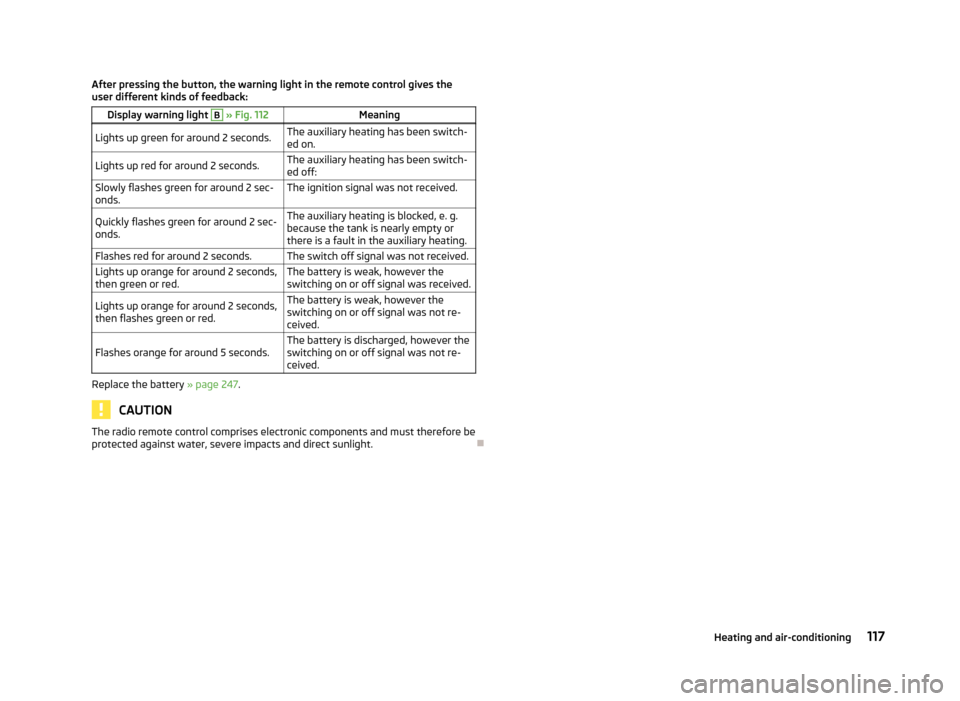
After pressing the button, the warning light in the remote control gives the
user different kinds of feedback:Display warning light B » Fig. 112MeaningLights up green for around 2 seconds.The auxiliary heating has been switch-
ed on.Lights up red for around 2 seconds.The auxiliary heating has been switch-
ed off:Slowly flashes green for around 2 sec- onds.The ignition signal was not received.Quickly flashes green for around 2 sec-
onds.The auxiliary heating is blocked, e. g.
because the tank is nearly empty or
there is a fault in the auxiliary heating.Flashes red for around 2 seconds.The switch off signal was not received.Lights up orange for around 2 seconds,
then green or red.The battery is weak, however the
switching on or off signal was received.Lights up orange for around 2 seconds,
then flashes green or red.The battery is weak, however the
switching on or off signal was not re-
ceived.Flashes orange for around 5 seconds.The battery is discharged, however the
switching on or off signal was not re-
ceived.
Replace the battery » page 247.
CAUTION
The radio remote control comprises electronic components and must therefore be
protected against water, severe impacts and direct sunlight.
117Heating and air-conditioning
Page 122 of 287
Power steeringFirst read and observe the introductory information and safety warn-ings
on page 118.
The power steering enables you to steer the vehicle with less physical force.
The power steering only works when the engine is running. It is still possible to fully steer the vehicle if the power steering fails or if the en-gine is not running (e.g. vehicle being towed in). However, greater physical effort is required to turn the steering wheel.
Steering force assistance can be influenced by the selection of driving mode » page 161 .
Starting and stopping the engine using the key
Introduction
This chapter contains information on the following subjects:
Electronic immobiliser
120
Ignition switch
120
Starting the engine
120
Stopping the engine
121
Starting and stopping the engine on vehicles with the KESSY system » page 121.
The engine can only be started with an appropriate original key.
The engine running noises may louder at first be louder for a short time after
starting the cold engine. This is quite normal and is not an operating problem.
WARNING■ When driving without the engine running, the ignition key must always be in
the position 2 » Fig. 115 on page 120 (ignition switched on). This position is
indicated by the illumination of certain indicator lights in the instrument clus-
ter. ■ If the key is not in position 2
, this could lead to unexpected the steering
locking - risk of accident!
■
Only pull the ignition key from the ignition lock when the vehicle has come
to a complete stop (by applying the handbrake). Otherwise the steering wheel
could block – risk of accident!
■
When leaving the vehicle, the ignition must always be removed. This is par-
ticularly important if children are left in the vehicle. Otherwise the children
could, for example, start the engine – risk of accident or injury!
■
Never leave the vehicle unattended with the engine running.
■
Never switch off the engine before the vehicle is stationary – risk of acci-
dent!
WARNING■ Never leave the engine running in unventilated or closed rooms. The ex-
haust gases from the engine contain substances such as odourless and col-
ourless carbon monoxide (a poisonous gas) – risk to life! ■ Carbon monoxide can cause unconsciousness and death.
CAUTION
■The starter must only be operated when the engine is not running and the vehi-
cle is at a standstill. The starter or engine may be damaged if the starter is activa- ted when the engine is running 3
» Fig. 115 on page 120.
■
Do not tow start the engine – there is a risk of damaging the engine and the
catalytic converter. The battery from another vehicle can be used as a jump-start
aid » page 243 , Jump-starting using the battery from another vehicle .
CAUTION
■
Avoid high engine revolutions, full throttle and high engine loads before the en-
gine has reached its operating temperature – risk of damaging the engine!■
Do not switch the engine off immediately at the end of your journey after the
engine has been operated over a prolonged period at high loads but leave it to
run at an idling speed for about 1 minute. This prevents any possible accumulation
of heat when the engine is switched off.
119Starting-off and Driving
Page 123 of 287
For the sake of the environmentDo not warm up the engine while the vehicle is stationary. If possible, start your
journey as soon as the engine has started. Through this the engine reaches its operating temperature more rapidly and the pollutant emissions are lower.
Note
After switching off the ignition, the radiator fan may intermittently continue to
operate for approx. 10 minutes.
Electronic immobiliser
First read and observe the introductory information and safety warn-
ings
on page 119.
An electronic chip is integrated in the head of the key. The immobiliser is deacti-
vated with the aid of this chip when the key is inserted in the ignition lock.
The electronic immobiliser is automatically activated when the ignition key is
withdrawn from the lock.
The engine will not start if a non-authorized ignition key is used.
The following message is shown in the information cluster display.
Immobilizer active.
IMMOBILIZER ACTIVE
Ignition switch
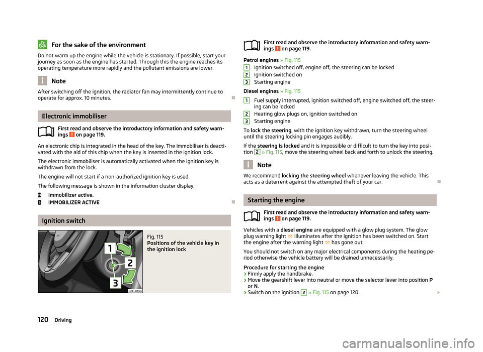
Fig. 115
Positions of the vehicle key in
the ignition lockFirst read and observe the introductory information and safety warn- ings on page 119.
Petrol engines » Fig. 115
Ignition switched off, engine off, the steering can be locked
Ignition switched on
Starting engine
Diesel engines » Fig. 115
Fuel supply interrupted, ignition switched off, engine switched off, the steer-
ing can be locked
Heating glow plugs on, ignition switched on
Starting engine
To lock the steering , with the ignition key withdrawn, turn the steering wheel
until the steering locking pin engages audibly.
If the steering is locked and it is impossible or difficult to turn the key into posi-
tion
2
» Fig. 115 , move the steering wheel back and forth to unlock the steering.
Note
We recommend locking the steering wheel whenever leaving the vehicle. This
acts as a deterrent against the attempted theft of your car.
Starting the engine
First read and observe the introductory information and safety warn-
ings
on page 119.
Vehicles with a diesel engine are equipped with a glow plug system. The glow
plug warning light
illuminates after the ignition has been switched on. Start
the engine after the warning light
has gone out.
You should not switch on any major electrical components during the heating pe- riod otherwise the vehicle battery will be drained unnecessarily.
Procedure for starting the engine
›
Firmly apply the handbrake.
›
Move the gearshift lever into neutral or move the selector lever into position P
or N.
›
Switch on the ignition
2
» Fig. 115 on page 120.
123123120Driving