ESP SKODA OCTAVIA 2015 3.G / (5E) Owner's Guide
[x] Cancel search | Manufacturer: SKODA, Model Year: 2015, Model line: OCTAVIA, Model: SKODA OCTAVIA 2015 3.G / (5E)Pages: 268, PDF Size: 37.54 MB
Page 74 of 268
The warning light goes out. The high beam turns off.›
If the headlight is not currently switched on automatically, move the lever in-
to position
A
(spring-tensioned position) .
The warning light
goes out. The high beam turns on.
Information message
The messages and information are indicated in the instrument cluster display.
Fault: Light AssistLIGHT ASSIST FAULT
Seek help from a specialist garage.
Light Assist: clean the windscreen!WINDSCREEN PLEASE CLEAN
Check for any obstacles on the windscreen in the viewing area of the sensors
of camera.
WARNINGThe system only serves as a support and does not relieve the driver of his
or her responsibility to check the headlights and low beam and, if necessa-
ry, to switch on the lights depending on the light conditions. The manual
operation may be required for example, in the following situations.■
When visibility is poor, e.g. fog, heavy rain, thick snowfall.
■
Passing poorly lit road users, e.g. cyclists or pedestrians.
■
When driving around “sharp” bends.
■
Driving through poorly-lit locations.
■
The camera or sensor viewing range is obstructed by an obstacle.
CAUTION
Do not attach any stickers or similar objects to the windscreen in front of the
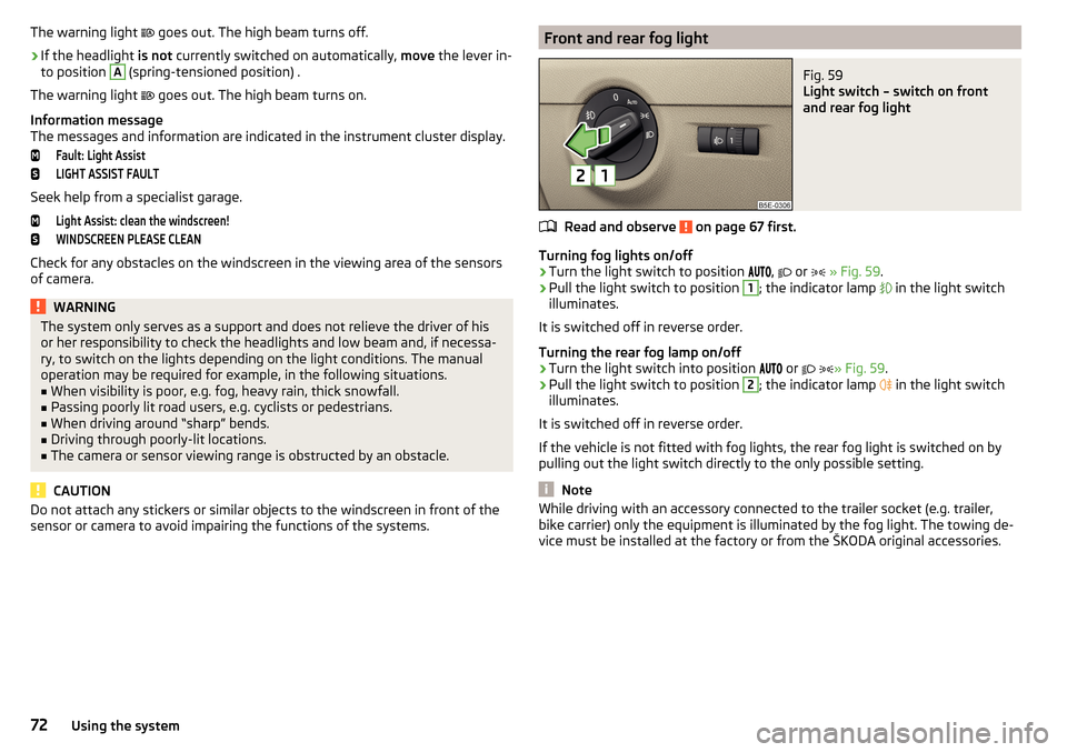
sensor or camera to avoid impairing the functions of the systems.Front and rear fog lightFig. 59
Light switch – switch on front
and rear fog light
Read and observe on page 67 first.
Turning fog lights on/off
›
Turn the light switch to position ,
or
» Fig. 59 .
›
Pull the light switch to position
1
; the indicator lamp
in the light switch
illuminates.
It is switched off in reverse order.
Turning the rear fog lamp on/off
›
Turn the light switch into position or
» Fig. 59
.
›
Pull the light switch to position
2
; the indicator lamp
in the light switch
illuminates.
It is switched off in reverse order.
If the vehicle is not fitted with fog lights, the rear fog light is switched on by pulling out the light switch directly to the only possible setting.
Note
While driving with an accessory connected to the trailer socket (e.g. trailer,
bike carrier) only the equipment is illuminated by the fog light. The towing de-
vice must be installed at the factory or from the ŠKODA original accessories.72Using the system
Page 84 of 268
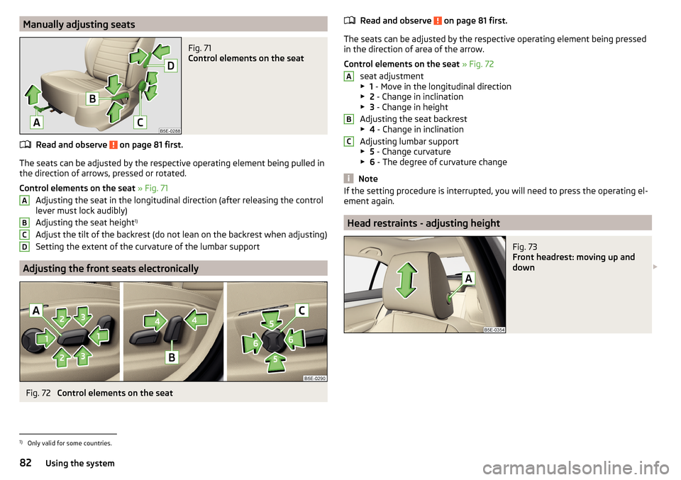
Manually adjusting seatsFig. 71
Control elements on the seat
Read and observe on page 81 first.
The seats can be adjusted by the respective operating element being pulled in
the direction of arrows, pressed or rotated.
Control elements on the seat » Fig. 71
Adjusting the seat in the longitudinal direction (after releasing the control
lever must lock audibly)
Adjusting the seat height 1)
Adjust the tilt of the backrest (do not lean on the backrest when adjusting)
Setting the extent of the curvature of the lumbar support
Adjusting the front seats electronically
Fig. 72
Control elements on the seat
ABCDRead and observe on page 81 first.
The seats can be adjusted by the respective operating element being pressed
in the direction of area of the arrow.
Control elements on the seat » Fig. 72
seat adjustment
▶ 1 - Move in the longitudinal direction
▶ 2 - Change in inclination
▶ 3 - Change in height
Adjusting the seat backrest
▶ 4 - Change in inclination
Adjusting lumbar support
▶ 5 - Change curvature
▶ 6 - The degree of curvature change
Note
If the setting procedure is interrupted, you will need to press the operating el-
ement again.
Head restraints - adjusting height
Fig. 73
Front headrest: moving up and
down
ABC1)
Only valid for some countries.
82Using the system
Page 85 of 268
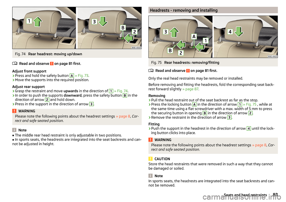
Fig. 74
Rear headrest: moving up/down
Read and observe
on page 81 first.
Adjust front support
›
Press and hold the safety button
A
» Fig. 73 .
›
Move the supports into the required position.
Adjust rear support
›
Grasp the restraint and move upwards in the direction of
1
» Fig. 74 .
›
In order to push the supports downward, press the safety button
B
in the
direction of arrow
2
and hold down.
›
Press in the support in the direction of arrow
3
.
WARNINGPlease note the following points about the headrest settings » page 8, Cor-
rect and safe seated position .
Note
■
The middle rear head restraint is only adjustable in two positions.■In sports seats, the headrests are integrated into the seat backrests and can-
not be adjusted in height.Headrests - removing and installingFig. 75
Rear headrests: removing/fitting
Read and observe
on page 81 first.
Only the real head restraints may be removed or installed.
Before removing and fitting the headrests, fold the corresponding seat back-
rest forward slightly » page 87.
Removing
›
Pull the head restraint out of the seat backrest as far as the stop.
›
Press the locking button
A
in the direction of arrow
1
» Fig. 75 , while at
the same time using a flat screwdriver with a max. width of 5 mm to press
the securing button in opening
B
in the direction of arrow
2
.
›
Remove the restraint in the direction of arrow
3
.
Fitting
›
Push the support in the headrest in the direction of arrow
4
until the lock-
ing button clicks into place.
WARNINGPlease note the following points about the headrest settings » page 8, Cor-
rect and safe seated position .
CAUTION
Store the head restraints that were removed in such a way that they cannot
be damaged or soiled.
Note
In sports seats, the headrests are integrated into the seat backrests and can-
not be removed.83Seats and head restraints
Page 90 of 268
›Fold the backrest in the direction of the arrow 2.
In the undivided seat back, press the release handles A
on both sides of the
seat back at the same time.
Folding forward from the luggage compartment
There is a lever on the left side of the luggage compartment for unlocking the
left rear seat backrest.
There is a lever on the right side of the luggage compartment for unlocking
the right and the middle rear seat backrests.
Before folding the seat backrest forward, check that there are no objects on
the rear seat.
On vehicles with a net partition, the left and then the right and middle rear
seat backrest must first be unlocked. The net partition must be rolled up in the
housing.
›
Pull the lever in the direction of the arrow » Fig. 82.
The respective seat rest is unlocked and folded forward if applicable.
Folding backwards
›
Pull the rear outer seat belt
C
to the side panel in the direction of arrow
3
» Fig. 81 .
›
Subsequently, fold back the backrest in the opposite direction of the arrow
2
until the release handle
A
clicks into place - by pulling on the seat back-
rest.
›
Make sure that the red pin
B
is hidden.
In the undivided seat back, pull the two outer belts to the side panel. The re-
lease handles
A
must be locked audibly on both sides of the seat backrest.
The red pen
B
should not be visible on any of the two sides of the seat back.
WARNING■ If rear seats are occupied, make sure that the respective seat backrests
are properly engaged.■
After folding back the seat back, the seat belts must be ready for use.
■
The seat backrests must be securely locked in position so that no objects
in the luggage compartment can slide into the passenger compartment on
sudden braking – risk of injury.
■
When transporting objects in the luggage compartment that has been en-
larged by folding the backrest forward, ensure the safety of the passengers
transported on the other rear seats.
CAUTION■ Ensure that the seat belts are not damaged when operating the seat backr-
ests. Under no circumstances must the rear seat belts be jammed by the fol-
ded back seat backrests.■
Before folding the seat back forward, check whether there are any objects
on the rear seat - there is a danger of damaging these items or the seat back
and the seat.
Long cargo channel in the rear seat backrest
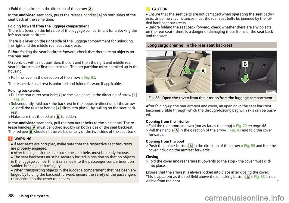
Fig. 83
Open the cover: from the interior/from the luggage compartment
After folding-up the rear armrest and cover, an opening in the seat backrest
becomes visible through which the through-loading bag with skis can be push-
ed.
Opening from the interior
›
Fold the rear armrest down (not as far as the stop) » Fig. 79 on page 86 .
›
Pull the handle
A
in the direction of the arrow » Fig. 83 and fold the cover
forwards.
Opening from the boot
›
Push the unlock button
B
in the direction of the arrow » Fig. 83 and fold the
cover including the armrest forwards.
Closing
›
Fold the cover and rear armrest upwards to the stop - the cover must click
into place.
Ensure that the armrest is always locked into place after closing the cover.
This is apparent as the red field above the unlocking button
B
» Fig. 83 is not
visible from the boot.
88Using the system
Page 102 of 268
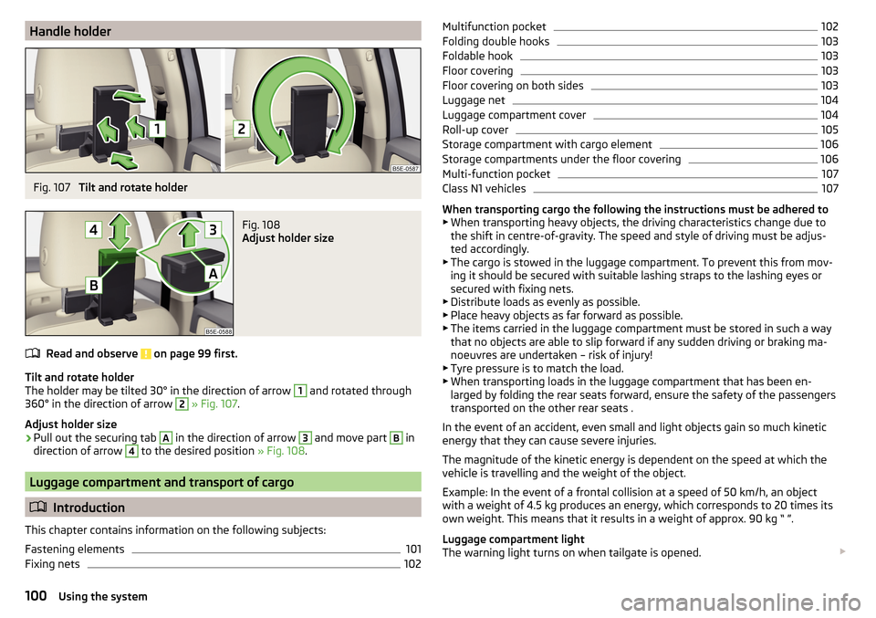
Handle holderFig. 107
Tilt and rotate holder
Fig. 108
Adjust holder size
Read and observe on page 99 first.
Tilt and rotate holder
The holder may be tilted 30° in the direction of arrow
1
and rotated through
360° in the direction of arrow
2
» Fig. 107 .
Adjust holder size
›
Pull out the securing tab
A
in the direction of arrow
3
and move part
B
in
direction of arrow
4
to the desired position » Fig. 108.
Luggage compartment and transport of cargo
Introduction
This chapter contains information on the following subjects:
Fastening elements
101
Fixing nets
102Multifunction pocket102Folding double hooks103
Foldable hook
103
Floor covering
103
Floor covering on both sides
103
Luggage net
104
Luggage compartment cover
104
Roll-up cover
105
Storage compartment with cargo element
106
Storage compartments under the floor covering
106
Multi-function pocket
107
Class N1 vehicles
107
When transporting cargo the following the instructions must be adhered to
▶ When transporting heavy objects, the driving characteristics change due to
the shift in centre-of-gravity. The speed and style of driving must be adjus-
ted accordingly.
▶ The cargo is stowed in the luggage compartment. To prevent this from mov-
ing it should be secured with suitable lashing straps to the lashing eyes or
secured with fixing nets.
▶ Distribute loads as evenly as possible.
▶ Place heavy objects as far forward as possible.
▶ The items carried in the luggage compartment must be stored in such a way
that no objects are able to slip forward if any sudden driving or braking ma-
noeuvres are undertaken – risk of injury!
▶ Tyre pressure is to match the load.
▶ When transporting loads in the luggage compartment that has been en-
larged by folding the rear seats forward, ensure the safety of the passengers
transported on the other rear seats .
In the event of an accident, even small and light objects gain so much kinetic
energy that they can cause severe injuries.
The magnitude of the kinetic energy is dependent on the speed at which the
vehicle is travelling and the weight of the object.
Example: In the event of a frontal collision at a speed of 50 km/h, an object
with a weight of 4.5 kg produces an energy, which corresponds to 20 times its
own weight. This means that it results in a weight of approx. 90 kg “ ”.
Luggage compartment light
The warning light turns on when tailgate is opened.
100Using the system
Page 103 of 268
The warning light turns off when the tailgate is closed.
If the boot lid is open and the ignition switched off, the light will extinguish
automatically after around 10 minutes.WARNING■ Never exceed the maximum permissible load of the respective fasteners,
nets, hooks etc. as heavy objects are not e sufficiently secured - there is a
risk of injury!■
If the cargo is tied down with unsuitable or damaged lashing straps, inju-
ries can occur in the event of braking manoeuvres or accidents.
■
Loose cargo can be thrown forward during a sudden manoeuvre or in case
of an accident and can injure the occupants or other road users.
■
Loose cargo could hit a deployed airbag and injure occupants – danger of
death!
CAUTION
■ Never exceed the maximum permissible load of the respective fasteners,
nets, hooks etc. - these could be damaged.■
Make sure that transported objects with sharp edges do not damage the
threads of the following devices. ■Rear window heater.
■ Rear window with an integrated antenna.
■ Integrated antenna in the rear side windows.
Fastening elements
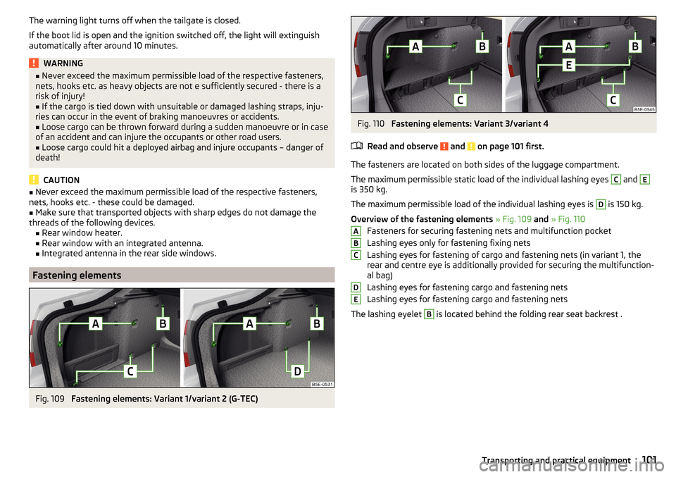
Fig. 109
Fastening elements: Variant 1/variant 2 (G-TEC)
Fig. 110
Fastening elements: Variant 3/variant 4
Read and observe
and on page 101 first.
The fasteners are located on both sides of the luggage compartment.
The maximum permissible static load of the individual lashing eyes
C
and
E
is 350 kg.
The maximum permissible load of the individual lashing eyes is
D
is 150 kg.
Overview of the fastening elements » Fig. 109 and » Fig. 110
Fasteners for securing fastening nets and multifunction pocket
Lashing eyes only for fastening fixing nets
Lashing eyes for fastening of cargo and fastening nets (in variant 1, the
rear and centre eye is additionally provided for securing the multifunction-
al bag)
Lashing eyes for fastening cargo and fastening nets
Lashing eyes for fastening cargo and fastening nets
The lashing eyelet
B
is located behind the folding rear seat backrest .
ABCDE101Transporting and practical equipment
Page 115 of 268
WARNING■For your own safety and that of other road users, ensure that all the win-
dows are free of ice, snow and misting. The blower should always be on to
prevent the windows from misting up.■
Under certain circumstances, air at a temperature of about 5 °C can flow
out of the vents when the cooling system is switched on.
CAUTION
■ The air inlet in front of the windscreen must be free of e.g. ice, snow or
leaves to ensure that the heating and cooling system operates properly.■
After switching on the cooling Condensation from the evaporator of the air
conditioning may drip down and form a puddle below the vehicle. This is not a
leak!
■
If the coolant temperature is too high, the cooling system is switched off to
ensure that the engine cools down.
Heating and manual air conditioning
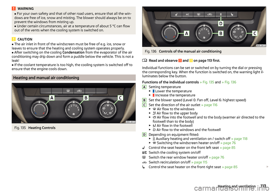
Fig. 135
Heating Controls
Fig. 136
Controls of the manual air conditioning
Read and observe
and on page 113 first.
Individual functions can be set or switched on by turning the dial or pressing
the corresponding key. When the function is switched on, the warning light il-
luminates below the button.
Functions of the individual controls » Fig. 135 and » Fig. 136
Setting temperature
▶ Lower the temperature
▶ Increase the temperature
Set the blower speed (Level 0: Fan off, Level 6: highest speed)
Set the direction of the air outlet » page 116
▶ Air flow to the windows
▶ Air flow to the upper body
▶ Air flow into the footwell and to the body (warmer air directed to the
footwell than to the body)
▶ Air flow in the footwell
▶ Air flow to the windows and the footwell
Depending on equipment fitted:
▶ Auxiliary heating and ventilation on / switch off
» page 118
▶ Switching the windscreen heater on/off
» page 76
Control the seat heater on the front left seat » page 85
Switch the cooling system on/off
Switch the rear window heater on/off » page 76
Switch recirculation on/off » page 115
Control the seat heater on the front right seat » page 85
ABCD113Heating and ventilation
Page 116 of 268
Information on the cooling system
The cooling system operates only if the following conditions are met
» page 112 .
The warning light below the button
» Fig. 136 illuminates after activation,
even if not all of the conditions for the function of the cooling system have
been met. The lighting up of the indicator light in the button signals the opera-
tional readiness of the cooling system.
When the air distribution control is turned to position
the cooling system is
activated.
Note
During operation of the manual air conditioning, an increase in engine idle
speed may occur under certain circumstances in order to ensure sufficient
heating comfort.
Climatronic (automatic air conditioning)
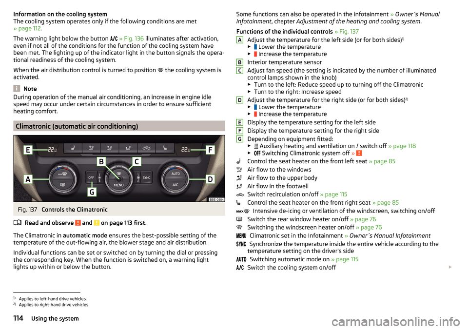
Fig. 137
Controls the Climatronic
Read and observe
and on page 113 first.
The Climatronic in automatic mode ensures the best-possible setting of the
temperature of the out-flowing air, the blower stage and air distribution.
Individual functions can be set or switched on by turning the dial or pressing
the corresponding key. When the function is switched on, a warning light
lights up within or below the button.
Some functions can also be operated in the infotainment » Owner´s Manual
Infotainment , chapter Adjustment of the heating and cooling system .
Functions of the individual controls » Fig. 137
Adjust the temperature for the left side (or for both sides) 1)
▶ Lower the temperature
▶ Increase the temperature
Interior temperature sensor
Adjust fan speed (the setting is indicated by the number of illuminated
control lamps shown in the knob) ▶ Turn to the left: Reduce speed up to turning off the Climatronic
▶ Turn to the right: Increase speed
Adjust the temperature for the right side (or for both sides) 2)
▶ Lower the temperature
▶ Increase the temperature
Display the temperature setting for the left side
Display the temperature setting for the right side
Depending on equipment fitted:
▶ Auxiliary heating and ventilation on / switch off
» page 118
▶ Switching Climatronic system off
»
Control the seat heater on the front left seat » page 85
Air flow to the windows
Air flow to the upper body
Air flow in the footwell
Switch recirculation on/off » page 115
Control the seat heater on the front right seat » page 85
Intensive de-icing or ventilation of the windscreen, switching on/off
Switch the rear window heater on/off » page 76
Switching the windscreen heater on/off » page 76
Climatronic set in the Infotainment » Owner´s Manual Infotainment
Synchronize the temperature inside the entire vehicle according to the
temperature setting on the driver's side
Switching automatic mode on » page 115
Switch the cooling system on/off
ABCDEFG1)
Applies to left-hand drive vehicles.
2)
Applies to right-hand drive vehicles.
114Using the system
Page 122 of 268
Driving
Starting-off and Driving
Starting and stopping the engine using the key
Introduction
This chapter contains information on the following subjects:
Electronic immobilizer
120
Steering lock locking / unlocking
120
Turning ignition on/off and starting the engine
121
Stopping the engine
121
With the key in the ignition, the ignition can be switched on and off and the
engine can be started / stopped.
WARNING■ While driving with the engine stopped, the ignition must always be
switched on » page 121, Turning ignition on/off and starting the engine .
■ With the ignition off, the steering may lock » page 120 - danger of an
accident!■
Do not withdraw the ignition key from the ignition lock until the vehicle
has come to a stop » page 128, Parking . Otherwise, the steering may lock -
danger of an accident!
■
Never leave the key in the vehicle when you exit the vehicle. Unauthor-
ized persons such as children could lock the car, turn on the ignition or start
the engine -risk of injury, accidents and damage!
■
Never leave the vehicle unattended with the engine running - there is
risk of accident, damage or theft!
■
Never switch off the engine before the vehicle is stationary – risk of acci-
dent!
WARNING■ Never (e.g. in garages) run the engine in a closed place - there is the dan-
ger of poisoning and death!■
Do not leave any items (e.g. cloths or tools) in the engine compartment.
This presents a fire hazard and the risk of engine damage.
■
Never cover the engine with additional insulation material (e.g. with a
blanket) – risk of fire!
CAUTION■ Only start the engine when the engine and the vehicle are stationary - there
is a danger of starter and engine damage!■
Do not push-start the engine – there is a risk of damaging the engine and
the catalytic converter. The battery from another vehicle can be used as a
jump-start aid » page 219.
Note
Do not warm up the engine while the vehicle is stationary. If possible, start
your journey as soon as the engine has started. Through this, the engine rea-
ches its operating temperature faster.
Electronic immobilizer
Read and observe
and on page 120 first.
The electronic immobiliser (hereinafter referred to as immobiliser) makes theattempted theft or unauthorised use of your vehicle more difficult.
An electronic chip is integrated in the head of the key. The immobiliser is deac-
tivated with the aid of this chip when the key is inserted in the ignition lock.
As soon as the ignition key is removed from the ignition lock, the immobiliser is
automatically activated.
Operational problems
If a component in the immobiliser key fails, it is not possible to start the en-
gine. A corresponding message appears in the display of the instrument clus-
ter to explain the immobiliser is active.
To start, use the other vehicle key or seek help from a specialist garage.
Steering lock locking / unlocking
Read and observe
and on page 120 first.
The steering lock (steering lock) deters any attempted theft of your vehicle.
Locking
›
Withdraw the ignition key.
›
Turn the steering wheel to the left or right until the steering lock clicks into
place.
Unlocking
›
Insert the key into the ignition lock.
120Driving
Page 134 of 268
›START STOP deactivate
» page 126, Manually deactivating/activating the
system .›
Fully depress and hold the brake pedal with your left foot.
›
Fully depress the accelerator pedal with your right foot.
›
Release the brake pedal.
The vehicle starts off with maximum acceleration.
›
Reactivate the TCS and START-STOP when the desired speed has been
reached.
WARNINGRapid acceleration, particularly on slippery roads, can lead to loss of control
of the vehicle – risk of accident!
Running-in and economical driving
Introduction
This chapter contains information on the following subjects:
Running-in
132
Tips for economical driving
132
DriveGreen function
133
The fuel consumption, degree of pollution and vehicle wear depend on driving
style, road condition, weather conditions and the like.
Running-in
Driving in the engine
The engine has to be run in during the first 1500 kilometres. During this period,
the driving style decides on the quality of the driving-in process.
During the first 1 000 km we recommend not driving faster than 3/4 of the
maximum permissible engine speed, not to drive at full throttle and to dis-
pense with the trailer.
In the area of 1,000 to 1,500 kilometres the engine load can be increased up
to the maximum permitted engine speed.
New tyres
New tyres have to be “run in” since they do not offer optimal grip at first.
Drive especially carefully for the first 500 km or so.
New brake pads
New brake pads have to first “grind in” because these do not initially have the
best possible braking effect.
Drive especially carefully for the first 200 km or so.
Tips for economical driving
To achieve the lowest possible fuel consumption, the following instructions
must be observed.
Looking ahead when driving
Avoid unnecessary acceleration and braking.
Switch in an energy saving and timely manner Observe the recommended gear » page 41.
Avoid full throttle and high speeds
Fuel consumption can be reduced by half if only three-quarters of the possible
top speed of your vehicle is used.
Reducing idling
If the vehicle is fitted with the START STOP system there is an automatic re-
duction of the idling. If the engine is stopped on vehicles without START-STOP
system, such as when waiting in a traffic jam, the fuel economy is already
greater after 30 - 40 s than the fuel quantity which is required for engine re-
start.
Avoid short distances
When driving a short distance of less than about 4 km, the engine cannot
reach its operating temperature. As long as the engine has not reached oper-
ating temperature, the fuel consumption is significantly higher than with the
engine hot.
Pay attention to the correct tyre inflation pressure being maintained
Further information » page 205.
Avoid unnecessary ballast
Per 100 kg of weight, consumption increases by about 0.3 l/100 km. At a speed
of 100 - 120 km/h, a vehicle fitted with a roof rack cross member without a load
will use about 10 % more fuel than normal due to the increased aerodynamic
drag.
Saving electricity
Only turn on electrical consumers (e.g. seat, window and mirror heating and
the like) for as long as necessary.
132Driving