technical data SKODA OCTAVIA TOUR 2010 2.G / (1Z) Owner's Guide
[x] Cancel search | Manufacturer: SKODA, Model Year: 2010, Model line: OCTAVIA TOUR, Model: SKODA OCTAVIA TOUR 2010 2.G / (1Z)Pages: 199, PDF Size: 12.09 MB
Page 42 of 199
Unlocking and locking41
Using the system
Safety
Driving Tips
General Maintenance
Breakdown assistance
Technical Data
Window convenience operation*You can open and close the window with power windows as follows when unlocking
and locking the vehicle.Opening a window– Hold the key in the locking cylinder of th e driver's door in the unlock position or
press the unlock button of the radio remote control until all the windows are
opened.Closing a window– Hold the key in the locking cylinder of the dr iver's door in the lock position or press
the lock button of the radio remote co ntrol until all the windows are closed.
You can interrupt the opening or closing operation of the windows immediately by
releasing the key or the lock button.
WARNING
The system is fitted with a force limiter page 40. If there is an obstacle, the
closing process is stopped and the window goes down by several centimetres.
You should then take particular care when closing the windows! You may
otherwise suffer severe injuries as a re sult of getting an arm, for example,
jammed in the window!
Note
On vehicles fitted with anti-theft alarm system the convenience window opening is
possible by means of the key in the locking cylinder only 45 seconds after deactivating
the warning system or after activa ting the anti-theft alarm system.Operational faultsElectrically operated power windows do not operate
If the battery of the car has been disconne cted and then reconnected, the electrically
operated power windows do not operate. The system must be activated. Proceed as
follows in order to re-establish the function:
Switch on the ignition.
Press the relevant switch top and hold it pressed as lo ng as necessary until the
window is closed.
Release the switch.
Press once again the relevant switch top and hold it pressed for approx. 3 seconds.
Operation in winter
Ice accumulating on the surface of the wi ndows during the winter may result in a
greater resistance when closing the windows and the window may stop and go down
several centimetres
It is necessary to put the force limiter out of operation in order to close the window
page 40, “Force limiter of the power windows”.
WARNING
The system is fitted with a force limiter page 40. If there is an obstacle, the
closing process is stopped and the window goes down by several centimetres.
You should then take particular care when closing the windows! You may
otherwise suffer severe injuries as a re sult of getting an arm, for example,
jammed in the window!
s2bs.2.book Page 41 Monday, September 27, 2010 9:53 AM
Page 44 of 199
Lights and Visibility43
Using the system
Safety
Driving Tips
General Maintenance
Breakdown assistance
Technical Data
Deactivating the function daylight driving lights– Pull the turn signal light lever towards the steering wheel up to 3 seconds after
switching on the ignition and at the same time, slide it to the bottom and hold it in
this position for at least 3 seconds.Activating the function daylight driving lights– Pull the turn signal light lever towards the steering wheel up to 3 seconds after
switching on the ignition and at the same time, slide it to the top and hold it in this
position for at least 3 seconds.
The daytime driving light is a combination of low-beam and parking light (front and
rear), including licence plate light.
When the daylight driving lights are switched on, the lighting of the instrument cluster
is switched on as well.Fog lights*
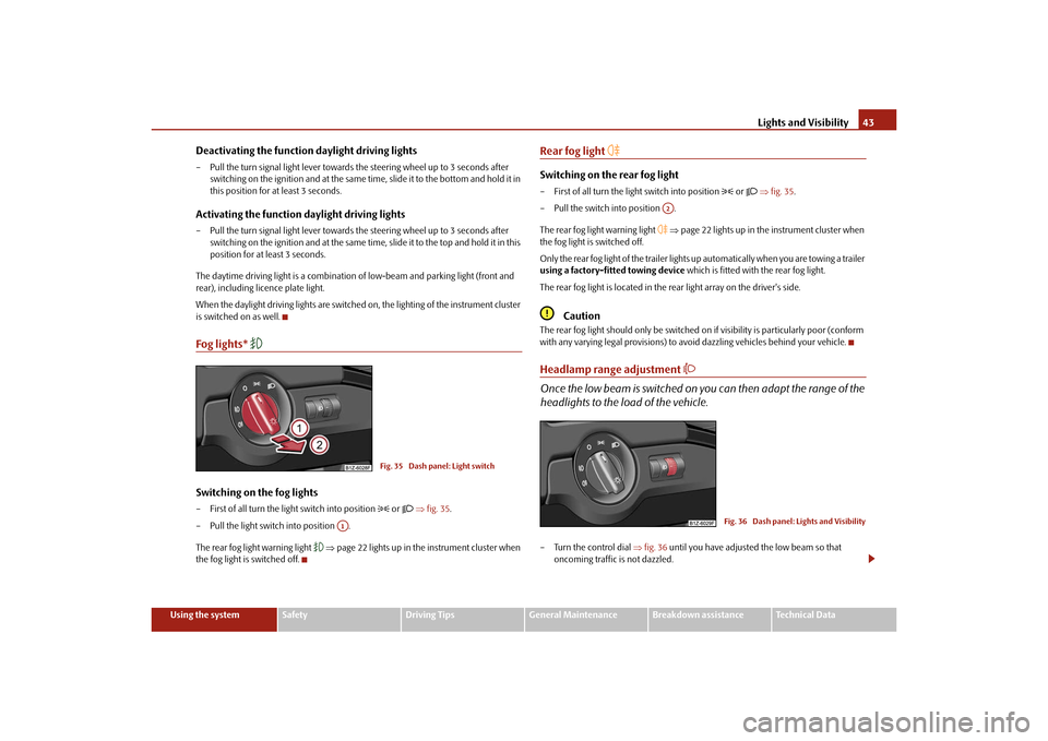
Switching on the fog lights– First of all turn the light switch into position
or fig. 35 .
– Pull the light switch into position .
The rear fog light warning light
page 22 lights up in the instrument cluster when
the fog light is switched off.
Rear fog light
Switching on the rear fog light– First of all turn the light switch into position
or fig. 35 .
– Pull the switch into position .
The rear fog light warning light
page 22 lights up in the instrument cluster when
the fog light is switched off.
Only the rear fog light of the trailer lights up automatically when you are towing a trailer
using a factory-fitted towing device which is fitted with the rear fog light.
The rear fog light is located in the rear light array on the driver's side.
Caution
The rear fog light should only be switched on if visibility is particularly poor (conform
with any varying legal provisions) to avoi d dazzling vehicles behind your vehicle.Headlamp range adjustment
Once the low beam is switched on you can then adapt the range of the
headlights to the load of the vehicle.– Turn the control dial fig. 36 until you have adjusted the low beam so that
oncoming traffic is not dazzled.
Fig. 35 Dash panel: Light switch
A1
A2
Fig. 36 Dash panel: Lights and Visibility
s2bs.2.book Page 43 Monday, September 27, 2010 9:53 AM
Page 46 of 199
Lights and Visibility45
Using the system
Safety
Driving Tips
General Maintenance
Breakdown assistance
Technical Data
– Pull the lever towards the steering wheel (spring-tensioned position) in direction
of arrow - the main beam light goes off.
Headlight flasher
– Pull the lever towards the steering wheel (spring-tensioned position) in direction of arrow - the main beam and warning light
in the instrument cluster come
on.
Parking light
– Switch off the ignition.
– Push the lever up or down - the right-hand or left-hand parking light is switched on.
Information concerning the function of the lights.
The turn signal system only operates when the igniti on is switched on. The corre-
sponding indicator light
or in the instrument cluster also flashes.
The turn signal is automatically cancelled after negotiating a curve.
The indicator light flashes at twice its normal rate if a bulb of the turn signal light
fails.
The side light and rear light on the appropriate side of the vehicle are switched on
when the parking light is selected. The parking light only operates if the ignition is
switched off.Caution
Use main beam or the headlight flasher only if this does not risk dazzling other road
users.
Note
If you have switched on the right or left tu rn signal light and you switch off the igni-
tion, the parking light is not automatically switched on.
Use only in accordance with the legal requirements the described lighting and
signal systems.
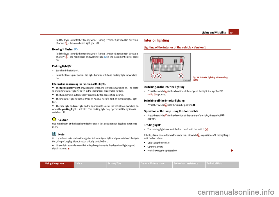
Interior lightingLighting of the interior of the vehicle - Version 1Switching on the interior lighting– Press the switch in the direction of the edge of the light, the symbol
fig. 39 appears.
Switching off the interior lighting– Press the switch into the middle position O.Operation of the lamp using the door switch– Press the switch in the direction of the centre of the light, the symbol
appears.
Reading lights– The reading lights are switched on or off with the switch .
If the lights are controlled via the door switch (switch in position
), the lighting is
switched on when:
Unlocking the vehicle
Opening doors
Withdrawing the ignition key.
ADAD
Fig. 39 Interior lighting with reading
lights
AAAAAA
AB
AA
s2bs.2.book Page 45 Monday, September 27, 2010 9:53 AM
Page 48 of 199
Lights and Visibility47
Using the system
Safety
Driving Tips
General Maintenance
Breakdown assistance
Technical Data
If the on-board voltage drops, the rear window heater is switched off automatically,
in order to provide sufficient electrical energy for the engine control.
Sun visorsYou can pull the sun visor for the driver or front passenger out of the fixture and swivel
it toward the door in the direction of the arrow fig. 42 .
A vanity mirror*, which is provided with a cover, is located in the front passenger side
sun visor. Push the cover in direction of arrow .
WARNING
The sun visors must not be swivelled to the side windows into the deployment
area of the head airbags if any objects, such as ball-point pens etc. are attached
to them. This might result in injuries to the occupants if the head airbag is
deployed.
Windshield wiper and wash systemWindshield wiper
You can operate the windscreen wipers and automatic wipe/wash
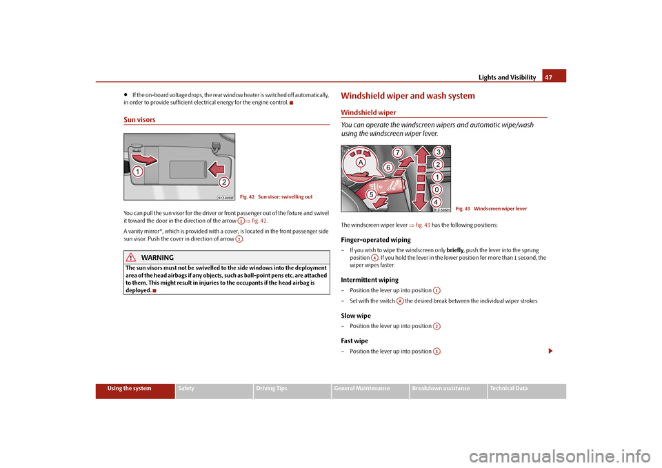
using the windscreen wiper lever.The windscreen wiper lever fig. 43 has the following positions:Finger-operated wiping– If you wish to wipe the windscreen only briefly, push the lever into the sprung
position . If you hold the lever in the lower position for more than 1 second, the
wiper wipes faster.Intermittent wiping– Position the lever up into position .
– Set with the switch the desired brea k between the individual wiper strokesSlow wipe– Position the lever up into position .Fast wipe– Position the lever up into position .
Fig. 42 Sun visor: swivelling outA1A2
Fig. 43 Windscreen wiper lever
A4
A1
AA
A2A3
s2bs.2.book Page 47 Monday, September 27, 2010 9:53 AM
Page 50 of 199
Lights and Visibility49
Using the system
Safety
Driving Tips
General Maintenance
Breakdown assistance
Technical Data
Note
If the slower or the faster wiper setting is switched on page 47, fig. 43 and
the vehicle speed decreases to below 4 km/h, the lower wiper step is switched on
automatically. At a speed increase of more than 8 km/h the previous wiper setting is
established again.
If there is an obstacle on the windscreen, the wiper will try to push away the
obstacle. If the obstacle continues to block the wiper, the wiper stops after 5 cycles, in
order to avoid a damage to the wiper. Remo ve the obstacle and switch on the wiper
again.
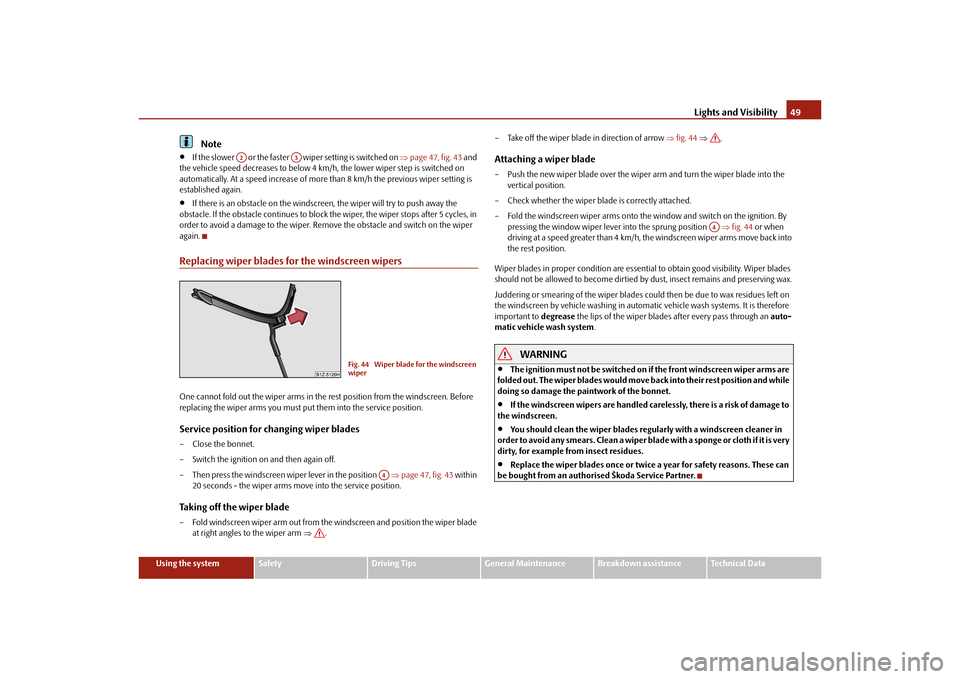
Replacing wiper blades for the windscreen wipersOne cannot fold out the wiper arms in the re st position from the windscreen. Before
replacing the wiper arms you must put them into the service position.Service position for changing wiper blades– Close the bonnet.
– Switch the ignition on and then again off.
– Then press the windscreen wiper lever in the position page 47, fig. 43 within
20 seconds - the wiper arms move into the service position.Taking off the wiper blade– Fold windscreen wiper arm out from the windscreen and position the wiper blade at right angles to the wiper arm . – Take off the wiper blade in direction of arrow
fig. 44 .
Attaching a wiper blade– Push the new wiper blade ov er the wiper arm and turn the wiper blade into the
vertical position.
– Check whether the wiper blade is correctly attached.
– Fold the windscreen wiper arms onto the window and switch on the ignition. By pressing the window wiper leve r into the sprung position fig. 44 or when
driving at a speed greater than 4 km/h, the windscreen wiper arms move back into
the rest position.
Wiper blades in proper condition are essentia l to obtain good visibility. Wiper blades
should not be allowed to become dirtied by dust, insect remains and preserving wax.
Juddering or smearing of the wiper blades co uld then be due to wax residues left on
the windscreen by vehicle wash ing in automatic vehicle wash systems. It is therefore
important to degrease the lips of the wiper blades after every pass through an auto-
matic vehicle wash system .
WARNING
The ignition must not be switched on if the front windscreen wiper arms are
folded out. The wiper blades would move back into their rest position and while
doing so damage the paintwork of the bonnet.
If the windscreen wipers are handled ca relessly, there is a risk of damage to
the windscreen.
You should clean the wiper blades regularly with a windscreen cleaner in
order to avoid any smears. Clean a wiper blad e with a sponge or cloth if it is very
dirty, for example fr om insect residues.
Replace the wiper blades once or twice a year for safety reasons. These can
be bought from an authorised Škoda Service Partner.
A2
A3
Fig. 44 Wiper blade for the windscreen
wiper
A4
A4
s2bs.2.book Page 49 Monday, September 27, 2010 9:53 AM
Page 52 of 199
Lights and Visibility51
Using the system
Safety
Driving Tips
General Maintenance
Breakdown assistance
Technical Data
WARNING
Convex (curved outward) or spherical (differently curved) exterior mirrors
increase the vision field. They do, howe ver, make objects appear smaller in the
mirror. These mirrors are only of limited use, therefore, for estimating distances
to the following vehicles.
Use whenever possible the interior rear mirror, for estimating the distances
to the following vehicles.Note
Do not touch the surfaces of the exterior mirrors if the exterior mirror heater is
switched on.
You can set the exterior mirr ors by hand, if the power setting function fails at any
time by pressing on the edge of the mirror surface.
Contact your specialist garage if a fault ex ists with the power setting of the exterior
mirrors.
s2bs.2.book Page 51 Monday, September 27, 2010 9:53 AM
Page 54 of 199
Seats and Stowage53
Using the system
Safety
Driving Tips
General Maintenance
Breakdown assistance
Technical Data
Adjusting lumbar support*– Turn the wheel until you have set the most comfortable curvature of the seat
upholstery in the area of your spine.
The driver's seat should be adjusted in such a way that the pedals can be fully pressed
to the floor with slightly bent legs.
The seat backrest on the driver's seat should be adjusted in such a way that the upper
point of the steering wheel can be easi ly reached with slightly bent arms.
WARNING
Only adjust the driver seat when the vehicle is stationary - risk of injury!
Take care when adjusting the seat! Adjusting the seat without care can lead
to bruises or injuries.
The seat backrests must not be angled too far back when driving otherwise
this will affect proper operation of the se at belts and of the airbag system - risk
of injury!
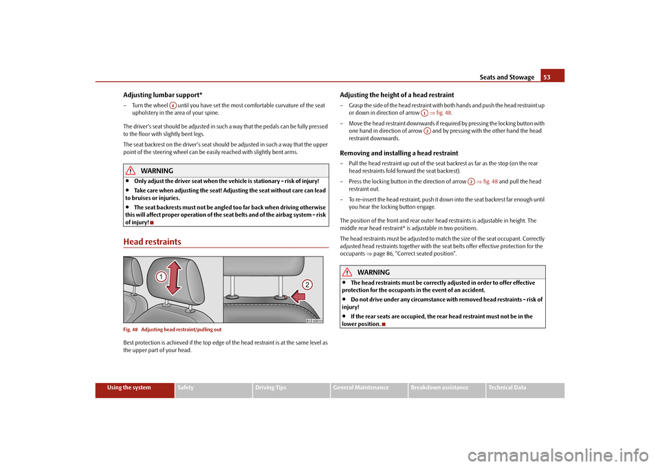
Head restraintsFig. 48 Adjusting head restraint/pulling outBest protection is achieved if the top edge of the head restraint is at the same level as
the upper part of your head.
Adjusting the height of a head restraint– Grasp the side of the head restraint with both hands and push the head restraint up
or down in direction of arrow fig. 48 .
– Move the head restraint downwards if required by pressing the locking button with one hand in direction of arrow and by pressing with the other hand the head
restraint downwards.Removing and installing a head restraint– Pull the head restraint up out of the seat backrest as far as the stop (on the rear
head restraints fold forward the seat backrest).
– Press the locking button in the direction of arrow fig. 48 and pull the head
restraint out.
– To re-insert the head restraint, push it do wn into the seat backrest far enough until
you hear the locking button engage.
The position of the front and rear outer head restraints is adjustable in height. The
middle rear head restraint* is adjustable in two positions.
The head restraints must be adjusted to ma tch the size of the seat occupant. Correctly
adjusted head restraints together with the seat belts offer effective protection for the
occupants page 86, “Correct seated position”.
WARNING
The head restraints must be correctly adjusted in order to offer effective
protection for the occupants in the event of an accident.
Do not drive under any circumstance with removed head restraints - risk of
injury!
If the rear seats are occupied, the rear head restraint must not be in the
lower position.
A4
A1A2
A2
s2bs.2.book Page 53 Monday, September 27, 2010 9:53 AM
Page 56 of 199
Seats and Stowage55
Using the system
Safety
Driving Tips
General Maintenance
Breakdown assistance
Technical Data
Move seats into the initial positionMove seats into the initial position– Install the head restraint in the slightly lifted seat backrest.
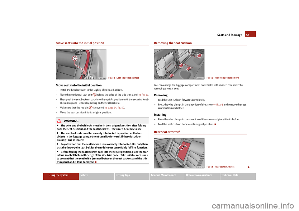
– Place the rear lateral seat belt be hind the edge of the side trim panel fig. 51 .
– Then push the seat backrest back into th e upright position until the securing knob
clicks into place - check by pulling on the seat backrest.
– Make sure that the red pin is covered page 54, fig. 50 .
– Move the seat cushion into its original position.
WARNING
The belts and the belt locks must be in their original position after folding
back the seat cushions and the seat backrests - they must be ready to use.
The seat backrests must be securely interlocked in position so that no
objects in the luggage compartment can slide forwards if there is sudden
braking - risk of injury!
Pay attention that the seat backrests are correctly interlocked. It is only then
that the three-point seat belt for the middle seat can reliably fulfil its function.
Before folding the seat backrest back in to the secure position, place the rear
lateral seat belt behind the edge of the si de trim panel. Take suitable measures
to prevent that the seat belt is jammed between the seat backrest and the side
trim panel and is thus damaged.
Removing the seat cushionYou can enlarge the luggage compartment on vehicles with divided rear seats* by
removing the rear seat.Removing– Fold the seat cushion forwards completely.
– Press the wire clamps in the direction of the arrow fig. 52 and remove the seat
cushion from its holder.Installing– Press the wire clamps in the direction of the arrow and place it in its holder.
– Fold the seat cushion back into its original position.Rear seat armrest*
Fig. 51 Lock the seat backrest
AC
AB
Fig. 52 Removing seat cushionsFig. 53 Rear seats: Armrest
s2bs.2.book Page 55 Monday, September 27, 2010 9:53 AM
Page 58 of 199
Seats and Stowage57
Using the system
Safety
Driving Tips
General Maintenance
Breakdown assistance
Technical Data
luggage compartmentLoading the luggage compartmentPlease observe the following in the interest of having good handling characteristics of
your vehicle:
– Distribute the items of luggage as evenly as possible.
– Place heavy objects as far forward as possible.
– Attach the items of luggage to the lashing eyes or the fixing net* page 58.
In the event of an accident, there is such a high kinetic energy which is produced by
small and light objects that th ey can cause severe injuries. The magnitude of the kinetic
energy depends on the speed at which the vehi cle is travelling and on the weight of the
object. The speed at which the vehicle is travelling is in this case the more significant
factor.
Example: In the event of a frontal collision at a speed of 50 km/h, an unsecured object
with a weight of 4.5 kg produces an ener gy, which corresponds to 20 times its own
weight. This means that it results in a weight of approx. 90 kg. You can imagine the inju-
ries that can occur, if this “bullet” is fl ying through the interior compartment and hits
an occupant.
WARNING
Stow the objects in the luggage compartment and attach them to the
lashing eyes.
Loose objects in the passenger compartment can be thrown forward during
a sudden manoeuvre or in case of an accident and can injure the occupants or
other oncoming traffic. This risk is still increased, if the objects which are flying
around are hit by a deployed airbag. In this case, the objects which are thrown
back can injure the occupants - hazard.
Please note that the handling properti es of your vehicle may be affected
when transporting heavy objects as a result of the displacement of the centre of
gravity. The speed and style of driv ing must be adjusted accordingly.
The items carried in the luggage compartment should be stowed in such a
way that no objects are able to slip fo rward if there are any sudden driving or
braking manoeuvres underta ken - risk of injury!
Never drive with the boot lid fully open ed or slightly ajar otherwise exhaust
gases may get into the interior of the vehicle - risk of poisoning!
On no account exceed the permissible axle loads and the permissible gross
weight of the vehicle - risk of accident!
Never transport occupants in the luggage compartment!Caution
Please ensure that the heating elements of the rear window heater are not damaged
as a result of objects sliding in this area.
Note
Tyre pressure must be adjusted to the load page 151.Vehicles of category N1On vehicles of the category N1, which are not fitted with a protective grille, a binding
device which complies with the standard EN 12195 (1 - 4) must be used for trans-
porting the goods.
WARNING (continued)
s2bs.2.book Page 57 Monday, September 27, 2010 9:53 AM
Page 60 of 199
Seats and Stowage59
Using the system
Safety
Driving Tips
General Maintenance
Breakdown assistance
Technical Data
Fixing nets - Net programme Combi*Fig. 57 Fixing net: Vertical pocket /division of the luggage compartmentFixing examples of the fixing net as pocket fig. 57 - left and as division of the luggage
compartment fig. 57 -right.
The floor fixing net is stow ed under the floor covering of the luggage compartment.
WARNING
The whole strength of the net makes it possible to load the pocket with objects
of up to 1.5 kg in weight. Heavy objects are not secured sufficiently - risk of
injury and net damage!
Caution
Do not place any objects with sharp edges in the nets - risk of net damage.
Folding hooks (Combi)Folding hooks for attaching small items of luggage, such as bags etc., are provided on
both sides of the luggage compartment fig. 58 .
An item of luggage weighing up to 10 kg can be attached to the hook.Fixing floor covering of the luggage compartmentFig. 59 Luggage compartment: Fixing of the floor covering Octavia/CombiThere is a loop (Octavia) or there are hook s (Combi) located on the floor covering of
the luggage compartment. You can fix the raised floor cover with a hook to the luggage
compartment cover (Octavia) fig. 59 - left, as if one needs to reach the spare wheel
or to the frame of the boot lid (Combi) fig. 59 - right.
Fig. 58 Luggage compartment: folding
hooks
s2bs.2.book Page 59 Monday, September 27, 2010 9:53 AM