boot SKODA RAPID SPACEBACK 2014 1.G User Guide
[x] Cancel search | Manufacturer: SKODA, Model Year: 2014, Model line: RAPID SPACEBACK, Model: SKODA RAPID SPACEBACK 2014 1.GPages: 204, PDF Size: 27.11 MB
Page 62 of 204

Switching on the parking light or parking lights1)
» page 63
Switch on low beam 1)
Pull switch Switch on the front fog lamp » page 61
Switching on the rear fog light » page 61
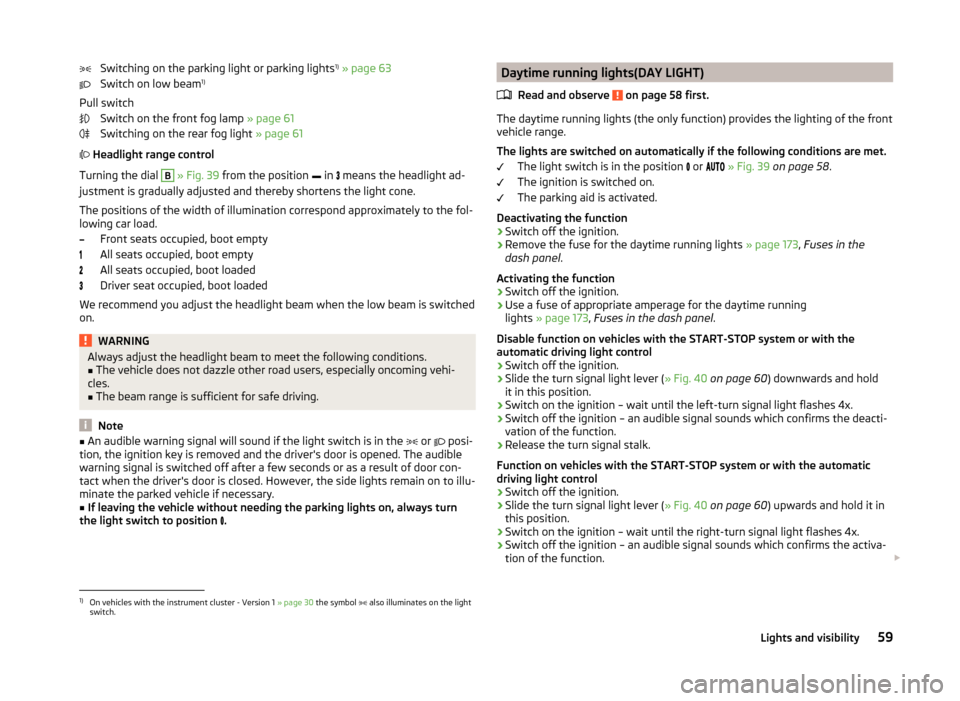
Headlight range control
Turning the dial B
» Fig. 39 from the position
in
means the headlight ad-
justment is gradually adjusted and thereby shortens the light cone.
The positions of the width of illumination correspond approximately to the fol- lowing car load.
Front seats occupied, boot empty
All seats occupied, boot empty
All seats occupied, boot loaded
Driver seat occupied, boot loaded
We recommend you adjust the headlight beam when the low beam is switched
on.
WARNINGAlways adjust the headlight beam to meet the following conditions.■The vehicle does not dazzle other road users, especially oncoming vehi-
cles.■
The beam range is sufficient for safe driving.
Note
■ An audible warning signal will sound if the light switch is in the or posi-
tion, the ignition key is removed and the driver's door is opened. The audible
warning signal is switched off after a few seconds or as a result of door con-
tact when the driver's door is closed. However, the side lights remain on to illu-
minate the parked vehicle if necessary.■
If leaving the vehicle without needing the parking lights on, always turn
the light switch to position
.
Daytime running lights(DAY LIGHT)
Read and observe
on page 58 first.
The daytime running lights (the only function) provides the lighting of the frontvehicle range.
The lights are switched on automatically if the following conditions are met. The light switch is in the position
or
» Fig. 39 on page 58 .
The ignition is switched on.
The parking aid is activated.
Deactivating the function
›
Switch off the ignition.
›
Remove the fuse for the daytime running lights » page 173, Fuses in the
dash panel .
Activating the function
›
Switch off the ignition.
›
Use a fuse of appropriate amperage for the daytime running
lights » page 173 , Fuses in the dash panel .
Disable function on vehicles with the START-STOP system or with the
automatic driving light control
›
Switch off the ignition.
›
Slide the turn signal light lever ( » Fig. 40 on page 60 ) downwards and hold
it in this position.
›
Switch on the ignition – wait until the left-turn signal light flashes 4x.
›
Switch off the ignition – an audible signal sounds which confirms the deacti-
vation of the function.
›
Release the turn signal stalk.
Function on vehicles with the START-STOP system or with the automatic
driving light control
›
Switch off the ignition.
›
Slide the turn signal light lever ( » Fig. 40 on page 60 ) upwards and hold it in
this position.
›
Switch on the ignition – wait until the right-turn signal light flashes 4x.
›
Switch off the ignition – an audible signal sounds which confirms the activa-
tion of the function.
1)
On vehicles with the instrument cluster - Version 1
» page 30 the symbol also illuminates on the light
switch.
59Lights and visibility
Page 65 of 204

COMING HOME / LEAVING HOMERead and observe
on page 58 first.
COMING HOME (hereinafter referred to only as a function) switches the light
automatically for a short time after leaving the vehicle.
LEAVING HOME (hereinafter referred to only as a function) switches the light
automatically for a short time when approaching the vehicle.
The function switches on the following light, depending on the equipment
fitted.
› Parking lights
› Low beam
› Entry lighting in the exterior mirrors
› Licence plate light
Poorer visibility is evaluated by sensor mounted in the holder of the interior
mirror.
COMING HOME
The lights are switched on automatically if the following conditions are met.
The light switch is in position
» Fig. 41 on page 60 .
The visibility in the vehicle environment is reduced.
The ignition is switched off.
The function was activated before leaving the vehicle by briefly switching
on the headlight flasher » page 60, Turn signal and main beam .
The driver's door was open - within 60 seconds after turning off the igni-
tion.
The light goes out 10 seconds after closing all of the doors and the boot lid.
If a door or the boot lid remains open, the light goes out after 60 seconds.
LEAVING HOME
The lights are switched on automatically if the following conditions are met.
The light switch is in position
» Fig. 41 on page 60 .
The visibility in the vehicle environment is reduced.
The ignition is switched off.
The vehicle was unlocked with the radio remote control.
The light goes off after 10 seconds or when locking the vehicle.
CAUTION■
Do not attach any stickers or similar objects in front of the light sensor on
the windscreen to avoid impairing the function or its reliability.■
If this function is activated constantly, the battery will be heavily discharged
particularly in short-haul travel.
Hazard warning light system
Fig. 43
Button for hazard warning light
system
Read and observe on page 58 first.
Switching on/off
›
Press the button
» Fig. 43 .
All the turn signal lights on the vehicle flash at the same time when the hazard
warning light system is switched on. The warning light for the turn signals and
the warning light in the button also flash at the same time. The hazard warn-
ing light system can also be operated if the ignition is switched off.
If one of the airbags is deployed, the hazard warning light system will switch
on automatically.
If the turn signal light is switched on when the hazard warning light and the
ignition are both switched on, then only the turn signal light on the corre-
sponding vehicle side will flash.
WARNINGSwitch on the hazard warning light system if, for example, the following oc-
curs.■
You encounter a traffic congestion.
■
The vehicle must may have to be parked on the roadside due to a fault.
62Using the system
Page 83 of 204

Net pockets on the front seat restFig. 74
Meshed pocket
Read and observe on page 73 first.
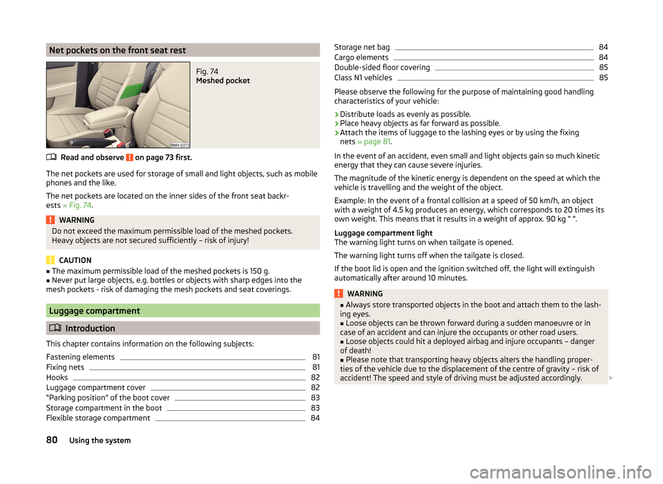
The net pockets are used for storage of small and light objects, such as mobile
phones and the like.
The net pockets are located on the inner sides of the front seat backr-
ests » Fig. 74 .
WARNINGDo not exceed the maximum permissible load of the meshed pockets.
Heavy objects are not secured sufficiently – risk of injury!
CAUTION
■ The maximum permissible load of the meshed pockets is 150 g.■Never put large objects, e.g. bottles or objects with sharp edges into the
mesh pockets - risk of damaging the mesh pockets and seat coverings.
Luggage compartment
Introduction
This chapter contains information on the following subjects:
Fastening elements
81
Fixing nets
81
Hooks
82
Luggage compartment cover
82
“Parking position” of the boot cover
83
Storage compartment in the boot
83
Flexible storage compartment
84Storage net bag84Cargo elements84
Double-sided floor covering
85
Class N1 vehicles
85
Please observe the following for the purpose of maintaining good handling
characteristics of your vehicle:
›
Distribute loads as evenly as possible.
›
Place heavy objects as far forward as possible.
›
Attach the items of luggage to the lashing eyes or by using the fixing
nets » page 81 .
In the event of an accident, even small and light objects gain so much kinetic
energy that they can cause severe injuries.
The magnitude of the kinetic energy is dependent on the speed at which the
vehicle is travelling and the weight of the object.
Example: In the event of a frontal collision at a speed of 50 km/h, an object
with a weight of 4.5 kg produces an energy, which corresponds to 20 times its
own weight. This means that it results in a weight of approx. 90 kg “ ”.
Luggage compartment light
The warning light turns on when tailgate is opened.
The warning light turns off when the tailgate is closed.
If the boot lid is open and the ignition switched off, the light will extinguish
automatically after around 10 minutes.
WARNING■ Always store transported objects in the boot and attach them to the lash-
ing eyes.■
Loose objects can be thrown forward during a sudden manoeuvre or in
case of an accident and can injure the occupants or other road users.
■
Loose objects could hit a deployed airbag and injure occupants – danger
of death!
■
Please note that transporting heavy objects alters the handling proper-
ties of the vehicle due to the displacement of the centre of gravity – risk of
accident! The speed and style of driving must be adjusted accordingly.
80Using the system
Page 84 of 204

WARNING (Continued)■If the items of luggage or objects are attached to the lashing eyes with
unsuitable or damaged lashing straps, injuries can occur in the event of
braking manoeuvres or accidents. To prevent items of luggage from moving
around, always use suitable lashing straps that are firmly attached to the
lashing eyes.■
The transported items must be stowed in such a way that no objects are
able to slip forward on sudden driving or braking manoeuvres – risk of in-
jury!
■
When transporting objects in the luggage compartment that has been en-
larged by folding the rear seats forward, ensure the safety of the passen-
gers transported on the other rear seats » page 11, Correct seated position
for the passengers in the rear seats .
■
If the rear seat next to the folded forward seat is occupied, ensure maxi-
mum safety, e.g. by placing the goods to be transported in such a way that
the seat is prevented from folding back in case of a rear collision.
■
Do not drive with the luggage compartment lid open or unlatched, other-
wise exhaust gases may get into the interior of the vehicle – risk of poison-
ing!
■
Do not exceed the permissible axle loads and permissible gross weight of
the vehicle – risk of accident!
■
Do not transport people in the boot!
CAUTION
■ Please ensure that the heating elements for the rear window heater are not
damaged as a result of abrasive objects.■
Tyre pressure must be adjusted to the load » page 153.
Fastening elements
Fig. 75
Fasteners
Read and observe and on page 80 first.
Overview of the fasteners » Fig. 75
Lashing eyelets for fastening items of luggage and fixing nets
Fastening element only for fastening fixing nets
Lashing eyes only for fastening fixing nets
The upper front lashing eye
C
is located behind the folding rear seat backrest.
CAUTION
The maximum permissible static load of the individual lashing eyes A is 3.5 kN
(350 kg).
Fixing nets
Fig. 76
Fastening examples for nets
ABC81Transporting and practical equipment
Page 85 of 204

Fig. 77
Fastening vertical pocket
Read and observe and on page 80 first.
Fastening examples for nets » Fig. 76
Horizontal pocket
Floor net
Vertical pocket
WARNINGDo not exceed the maximum permissible load of the fixing nets. Heavy ob-
jects are not secured sufficiently – risk of injury!
CAUTION
■ The maximum permissible load of the fixing nets is 1.5 kg.■Do not place any sharp objects in the nets – risk of net damage.
Hooks
Fig. 78
Hooks
Read and observe and on page 80 first.
The hook is used to affix small items of luggage such as bags.
The hooks are located on both sides of the luggage compartment » Fig. 78.
ABCCAUTIONThe maximum permissible load of the hook is 7.5 kg.
Luggage compartment cover
Fig. 79
Removing the boot cover
Read and observe
and on page 80 first.
The boot cover can be removed if you want to transport bulky goods.
Removing
›
Unhook the retaining straps
A
from the flap in the direction of arrow
1
» Fig. 79 .
›
Hold the cover in the upper position and press the bottom of the cover in the
area of the pin
C
.
›
Remove the cover in the direction of the arrow
2
.
The dismantled luggage compartment cover can be stowed away behind the
rear seat backrest in the so called “parking position” » page 83.
Installing
›
Place the cover on the contact surfaces of the side trim panel.
›
Position the mounts on the cover
B
onto the side trim panel via pins
C
» Fig. 79 .
›
Press on the upper side of the cover so that the mounts fully interlock into
the pins.
›
Insert the retaining bands
A
opposite to the direction of arrow
1
on the
boot lid.
82Using the system
Page 86 of 204

WARNINGNo objects may be placed on the boot cover, the vehicle occupants could be
endangered if there is sudden braking or the vehicle collides with some-
thing.
CAUTION
■ The maximum permissible load of the luggage compartment cover is 1 kg.■When closing the boot lid, jamming and damage to the luggage compartment
cover or the side trim panel can occur if handled in an unprofessional way. The
following guidelines must be observed. ■ The holders B
on the cover must be resting completely on the pins
C
on
the side panel » Fig. 79.
■ The items which are transported must not exceed the height of the lug-
gage compartment cover in the lower position.
■ The cover must not be jammed in the surrounding seal of the luggage com-
partment lid when it is in the upper position. ■ There must be no object in the gap between the cover in the upper posi-
tion and the rear backrest.
■
After removing the luggage compartment cover, store it in such a way that it
cannot be damaged or soiled.
Note
If the support straps A » Fig. 79 are attached to the boot, then the boot cover
will raise when the boot is opened.
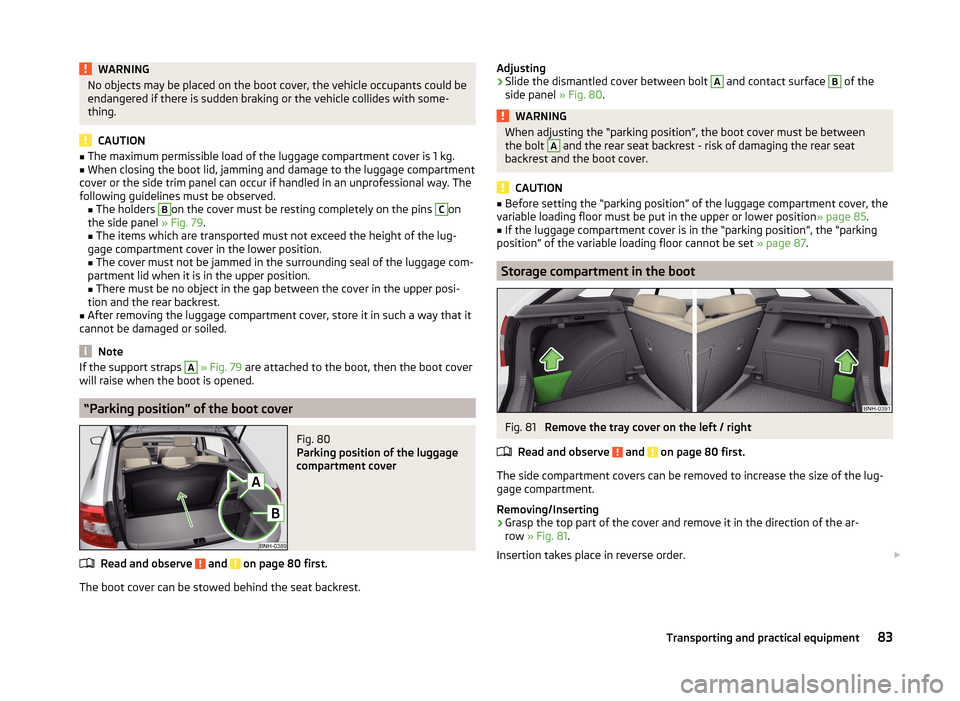
“Parking position” of the boot cover
Fig. 80
Parking position of the luggage
compartment cover
Read and observe and on page 80 first.
The boot cover can be stowed behind the seat backrest.
Adjusting›Slide the dismantled cover between bolt A and contact surface B of the
side panel » Fig. 80.WARNINGWhen adjusting the “parking position”, the boot cover must be between
the bolt A and the rear seat backrest - risk of damaging the rear seat
backrest and the boot cover.
CAUTION
■ Before setting the “parking position” of the luggage compartment cover, the
variable loading floor must be put in the upper or lower position » page 85.■
If the luggage compartment cover is in the “parking position”, the “parking
position” of the variable loading floor cannot be set » page 87.
Storage compartment in the boot
Fig. 81
Remove the tray cover on the left / right
Read and observe
and on page 80 first.
The side compartment covers can be removed to increase the size of the lug- gage compartment.
Removing/Inserting
›
Grasp the top part of the cover and remove it in the direction of the ar-
row » Fig. 81 .
Insertion takes place in reverse order.
83Transporting and practical equipment
Page 87 of 204

CAUTION■The storage compartments are designed for storing small objects of up to
1.5 kg. in weight in total.■
When using the storage compartment, take care not to damage it or the lug-
gage compartment lining.
Flexible storage compartment
Fig. 82
Flexible storage compartment
Read and observe and on page 80 first.
The flexible storage compartment can be installed on the right-hand side of the boot » Fig. 82.
Installing
›
Place both ends of the storage compartment into the openings on the right
side panel of the luggage compartment.
›
Push the storage compartment down to lock it.
Removing
›
Grasp the storage compartment on the two upper corners.
›
Remove the storage compartment by pulling upwards and then towards you.
CAUTION
The storage compartment is designed for storing small objects with a maxi-
mum total weight of 8 kg.
Note
The flexible storage compartment cannot be installed on vehicles with the var-
iable loading floor » page 85.Storage net bagFig. 83
Meshed pocket for storage
Read and observe and on page 80 first.
The meshed pocket for storage is located on the right-hand side of the
boot » Fig. 83 .
CAUTION
The meshed pocket for storage is designed for storing small objects of up to
1.5 kg. in weight in total.
Cargo elements
Fig. 84
Removing cargo elements / example on how to mount the load by
means of the cargo element
Read and observe
and on page 80 first.
The Cargo elements can be used for mounting and securing of the load from
slipping in the boot.
The Cargo elements can be stored under the floor in the boot.
84Using the system
Page 90 of 204

CAUTION■When removing or inserting the variable loading floor, a distance of 15 cmB » Fig. 87 underneath the boot cover must be adhered to - risk of damaging
the boot lid seal.■
The variable loading floor cannot be placed in the vehicle when the luggage
compartment cover is in the “park position” » page 83.
Note
After removing the variable cargo floor, place it down in such a way that it can-
not be damaged or soiled.
Folding up/down
Fig. 88
Fold up/fold down variable loading floor
Read and observe
on page 85 first.
The variable loading floor can be folded up in both positions (upper and lower). Folding up
›
Grasp the variable loading floor at handle
A
» Fig. 88 .
›
Lift the variable loading floor in the direction of the arrow
1
until the folding
corners
B
lock into place in area
C
.
Folding down
›
Grasp the variable loading floor in the middle or at handle
A
» Fig. 88 .
›
Unlock the variable loading floor by pulling it in the direction of the arrow
2
.
“Parking position”Fig. 89
Set parking position / fold down from the parking position
Read and observe
on page 85 first.
The variable loading floor can only be in set to the “parking position” when it is in the lower position » page 86 and the luggage compartment cover has been
taken out » page 82.
Folding up
›
Remove the luggage compartment cover from the vehicle » page 82.
›
Grasp the variable loading floor at handle
A
» Fig. 89 .
›
Lift the variable loading floor in the direction of the arrow
1
until the folding
corners
B
lock into place in area
C
.
Folding down
›
Push the folding corners
B
» Fig. 89 on both sides of the variable loading
floor in the direction of the arrow
2
and release these from positions
C
.
›
Grasp the variable loading floor in the middle or at handle
A
.
›
Fold down the variable loading floor in the direction of arrow
3
.
WARNINGThe variable loading floor in the “parking position” restricts the driver's
view at the back.
CAUTION
■ The variable loading floor can only be in set to the “parking position” when it
is in the lower position and the luggage compartment cover has been taken
out.■
If the variable loading floor is in the “parking position”, the “parking position”
on the luggage compartment cover cannot be set » page 83.
87Transporting and practical equipment
Page 91 of 204

Roof rack
Introduction
This chapter contains information on the following subjects:
fixing points for base support
88
Roof load
88WARNING■ The transported items on the roof rack must be securely attached – risk
of accident!■
Always secure the load with appropriate and undamaged lashing straps
or tensioning straps.
■
Distribute the load evenly over the roof rack system.
■
When transporting heavy objects or objects which take up a large area on
the roof rack system, handling of the car may change as a result of the dis-
placement of the centre of gravity. The style of driving and speed must
therefore be adapted to the current circumstances.
■
Avoid abrupt and sudden driving/braking manoeuvres.
■
The permissible roof load, permissible axle loads and permissible total ve-
hicle weight must not be exceeded under any circumstance – risk of acci-
dent!
CAUTION
■ Only roof racks from the ŠKODA Original Accessories range should be used.■When dealing with roof rack systems, the installation instructions supplied
with the roof luggage rack system must be observed.■
On models fitted with a power sliding/tilting roof, ensure that the extended
sliding/tilting roof does not hit any items of luggage transported on the roof.
■
Ensure that the boot lid does not hit the roof load when opened.
■
The height of the vehicle changes after mounting a roof luggage rack system
and the load that is secured to it. Compare the vehicle height with available
clearances, such as underpasses and garage doors.
■
Always remove the roof luggage rack system before entering an automated
car wash.
■
Ensure the roof aerial is not impaired by the secured load.
For the sake of the environment
The increased aerodynamic drag results in a higher fuel consumption.fixing points for base supportFig. 90
Attachment points
Read and observe
and on page 88 first.
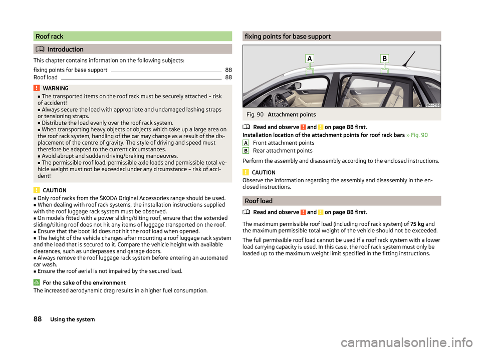
Installation location of the attachment points for roof rack bars » Fig. 90
Front attachment points
Rear attachment points
Perform the assembly and disassembly according to the enclosed instructions.
CAUTION
Observe the information regarding the assembly and disassembly in the en-
closed instructions.
Roof load
Read and observe
and on page 88 first.
The maximum permissible roof load (including roof rack system) of 75 kg and
the maximum permissible total weight of the vehicle should not be exceeded.
The full permissible roof load cannot be used if a roof rack system with a lower
load carrying capacity is used. In this case, the roof rack system must only be
loaded up to the maximum weight limit specified in the fitting instructions.
AB88Using the system
Page 106 of 204

This website contains information about the vehicle, the Wi-Fi connection and
SmartGate.
In the Configuration area the Wi-Fi connection settings can be adjusted.
Save the setting changes
The setting changes are only applied after performing the following steps.
› The changes are saved by pressing the “Save” button.
› SmartGate is restarted by pressing the “Reboot ”button.
Password Management
Read and observe
on page 102 first.
Password management can be done in the connected device on the Smart-
Gate website » page 102, Smart Gate website .
The changes are applied after saving and restarting SmartGate » page 103,
Save the setting changes .
Change password
›
Enter a new password in the Configuration area in menu option WPA / WPA2 key.
The password must be 8-17 characters without diacritics or special characters
(for example, -, /, etc.).
Connection option without entering a password
›
In the Configuration area set the value Open in the menu item Security .
Forgot password
If you have forgotten your password, SmartGate must be reset to factory set-
tings in a specialized workshop.
103Communication and multimedia