tow SKODA ROOMSTER 2010 1.G User Guide
[x] Cancel search | Manufacturer: SKODA, Model Year: 2010, Model line: ROOMSTER, Model: SKODA ROOMSTER 2010 1.GPages: 231, PDF Size: 12.91 MB
Page 62 of 231
Seats and Storage61
Using the system
Safety
Driving Tips
General Maintenance
Breakdown assistance
Praktik
Technical Data
Note
The outer seats are not replac eable alternatively. In the rear area the left seat is
marked with the letter L and the right seat with the letter R.
Please refer to the following guidelines page 111.
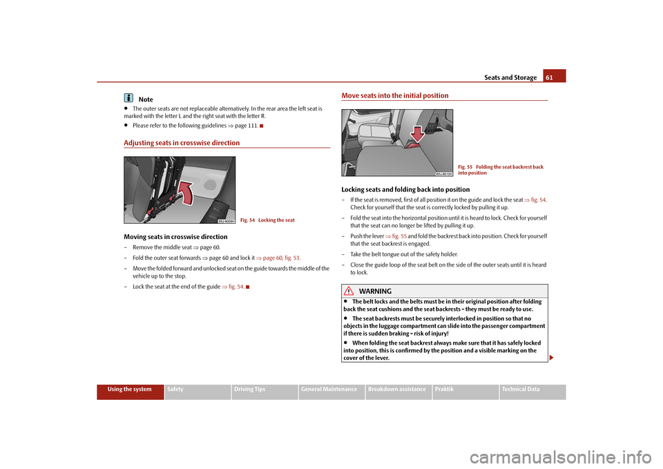
Adjusting seats in crosswise directionMoving seats in crosswise direction– Remove the middle seat page 60.
– Fold the outer seat forwards page 60 and lock it page 60, fig. 53 .
– Move the folded forward and unlocked seat on the guide towards the middle of the vehicle up to the stop.
– Lock the seat at the end of the guide fig. 54 .
Move seats into the initial positionLocking seats and folding back into position– If the seat is removed, first of all position it on the guide and lock the seat fig. 54 .
Check for yourself that the seat is correctly locked by pulling it up.
– Fold the seat into the horizontal position until it is heard to lock. Check for yourself that the seat can no longer be lifted by pulling it up.
– Push the lever fig. 55 and fold the backrest back in to position. Check for yourself
that the seat backrest is engaged.
– Take the belt tongue out of the safety holder.
– Close the guide loop of the seat belt on the side of the outer seats until it is heard to lock.
WARNING
The belt locks and the belts must be in their original position after folding
back the seat cushions and the seat backrests - they must be ready to use.
The seat backrests must be securely interlocked in position so that no
objects in the luggage compartment can slide into the passenger compartment
if there is sudden braking - risk of injury!
When folding the seat backrest always make sure that it has safely locked
into position, this is confirmed by the position and a visible marking on the
cover of the lever.
Fig. 54 Locking the seat
Fig. 55 Folding the seat backrest back
into position
s16g.4.book Page 61 Wednesda y, February 10, 2010 3:53 PM
Page 64 of 231
Seats and Storage63
Using the system
Safety
Driving Tips
General Maintenance
Breakdown assistance
Praktik
Technical Data
WARNING
Stow the objects in the luggage compartment and attach them to the
lashing eyes.
Loose objects in the passenger compartment can be thrown forward during
a sudden manoeuvre or in case of an accident and can injure the occupants or
other oncoming traffic. This risk is still increased, if the objects which are flying
around are hit by a deployed airbag. In this case, the objects which are thrown
back can injure the occupants - hazard.
Please note that the handling properti es of your vehicle may be affected
when transporting heavy objects as a result of the displacement of the centre of
gravity. The speed and style of driv ing must be adjusted accordingly.
The items carried in the luggage compar tment should be stowed in such a
way that no objects are able to slip fo rward if there are any sudden driving or
braking manoeuvres undertaken - risk of injury!
When transporting fastened objects which are sharp and dangerous in the
luggage compartment enlarged by folding the rear seats forward or removing
the rear seats, ensure the safety of the passengers transported on the other rear
seats page 111, “Correct seated position fo r the occupants on the rear seats”.
If the rear seats next to the folded forward seat are occupied, ensure
maximum safety, e.g. by placing the goods to be transported in such a way that
a folding back of the seat is prev ented in case of a rear collision.
Never drive with the boot lid fully open ed or slightly ajar otherwise exhaust
gases may get into the interior of the vehicle - risk of poisoning!
On no account exceed the permissible axle loads and the permissible gross
weight of the vehicle - risk of accident!
Never transport occupants in the luggage compartment.Caution
Please ensure that the heating elements of the rear window heater are not damaged
as a result of objects sliding in this area.
Note
Tyre pressure must be adjusted to the load page 173, fig. 143.
The circulation of air in the vehicle help s to prevent the windows from misting up.
The used air streams out through the air venting slits which are located under the
bumper in the luggage compartment. Check fo r yourself that the air venting slits are
not covered.
Vehicles of category N1On vehicles of the category N1, which are no t fitted with a protective grille, a lashing
set which complies with the standard EN 12195 (1 - 4) must be used for fastening the
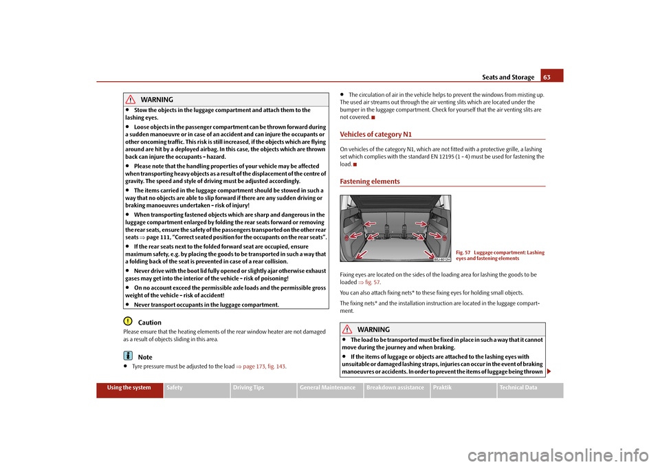
load.Fastening elementsFixing eyes are located on th e sides of the loading area for lashing the goods to be
loaded fig. 57 .
You can also attach fixing nets* to these fixing eyes for holding small objects.
The fixing nets* and the installation inst ruction are located in the luggage compart-
ment.
WARNING
The load to be transported must be fixed in place in such a way that it cannot
move during the journey and when braking.
If the items of luggage or objects are attached to the lashing eyes with
unsuitable or damaged lashing straps, inju ries can occur in the event of braking
manoeuvres or accidents. In order to prevent the items of luggage being thrown
Fig. 57 Luggage compartment: Lashing
eyes and fastening elements
s16g.4.book Page 63 Wednesday, February 10, 2010 3:53 PM
Page 67 of 231
Seats and Storage
66
– Insert the cross rod into the mount first on the one side and push the cross rod
forward. In the same way, fix the cross rod to the other side of the vehicle, mount
page 65, fig. 61 .
– Hang the carabines at the ends of the st rap into the lashing eyes behind the rear
seats.
– Pull the strap through the tensioning clasp, first of all on the one side and then on
the other side.Remove the static separation net behind the rear seats– Slacken the bands on both sides and take off the carabines page 65, fig. 61 .
– Push the cross rod first of all on the one side and then on the other side towards
the rear.
– Take the cross rod out of the mounts .Pack static separation net– Press the red button of the joint - so that it releases.
– Put the separation net folded together in the bag and close it.
– Attach the bag with the aid of the plastic carabines to the eyes on the left and right luggage compartment trim panel.
Installing and removing the static se paration net behind the front seats page 65,
fig. 61 on the right is carried out analogously as behind the rear seats. Use the eyes
behind the front seats to attach the carabi nes. Remove the rear seats to enlarge the
luggage compartment.
Installing and removing the static separation net behind the rear seats with variable
loading floor* page 66 is carried out analogously as behind the rear seats without
variable loading floor. Use the lower eyes at the fixing wedges on the front part of the
variable loading floor in or der to attach the carabines.
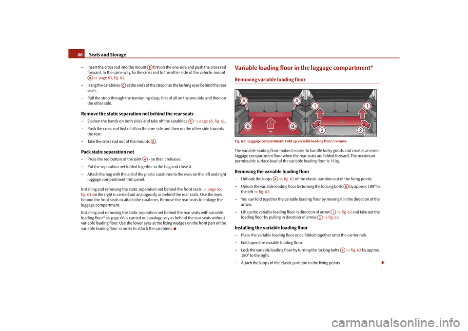
Variable loading floor in the luggage compartment*Removing variable loading floorFig. 62 Luggage compartment: Fold up variable loading floor / removeThe variable loading floor makes it easier to handle bulky goods and creates an even
luggage compartment floor when the rear seats are folded forward. The maximum
permissable surface load of the variable loading floor is 75 kg.Removing the variable loading floor– Unhook the loops fig. 62 of the elastic partition out of the fixing points.
– Unlock the variable loading floor by turnin g the locking bolts by approx. 180° to
the left fig. 62 .
– You can fold together the variable loading floor by moving it in the direction of the
arrow.
– Lift up the variable loading floor in direction of arrow fig. 62 and take out the
loading floor by pulling in direction of arrow fig. 62 .Installing the variable loading floor– Place the variable loading floor once folded together onto the carrier rails.
– Fold open the variable loading floor.
– Lock the variable loading floor by turning the locking bolts fig. 62 by approx.
180° to the right.
– Attach the loops of the elastic partition to the fixing points.
AB
AB
AC
AC
AB
AA
AA
AB
A1
A2
AB
s16g.4.book Page 66 Wednesda y, February 10, 2010 3:53 PM
Page 69 of 231
Seats and Storage
68
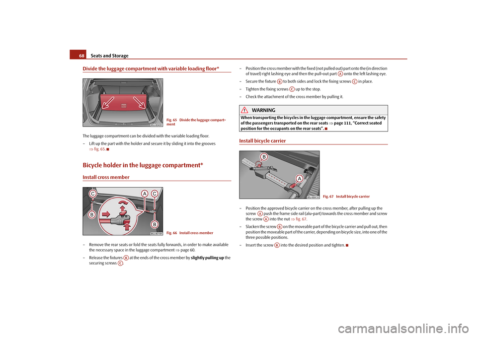
Divide the luggage compartment with variable loading floor*The luggage compartment can be divided with the variable loading floor.
– Lift up the part with the holder and secure it by sliding it into the grooves
fig. 65 .Bicycle holder in the luggage compartment*Install cross member– Remove the rear seats or fold the seats fully forwards, in order to make available
the necessary space in the luggage compartment page 60.
– Release the fixtures at the ends of the cross member by slightly pulling up the
securing screws . – Position the cross member with the fixed (not
pulled out) part onto the (in direction
of travel) right lashing eye and then the pull-out part onto the left lashing eye.
– Secure the fixture to both sides an d lock the fixing screws in place.
– Tighten the fixing screws up to the stop.
– Check the attachment of the cross member by pulling it.
WARNING
When transporting the bicycles in the luggage compartment, ensure the safety
of the passengers transported on the rear seats page 111, “Correct seated
position for the occupants on the rear seats”.Install bicycle carrier– Position the approved bicycle carrier on the cross member, after pulling up the
screw push the frame side rail (alu-part) towards the cross member and screw
the screw into the nut fig. 67 .
– Slacken the screw on the moveable part of the bicycle carrier and pull out, then
position the moveable part of the carrier, depending on bicycle size, into one of the
three possible positions.
– Insert the screw into the desired position and tighten.
Fig. 65 Divide the luggage compart-
mentFig. 66 Install cross member
AB
AC
AA
AB
AC
AC
Fig. 67 Install bicycle carrier
AAAA
ABAB
s16g.4.book Page 68 Wednesda y, February 10, 2010 3:53 PM
Page 74 of 231
Seats and Storage73
Using the system
Safety
Driving Tips
General Maintenance
Breakdown assistance
Praktik
Technical Data
WARNING
Take care when using the cigarette ligh ter! Not paying proper attention or
incorrect use the cigarette lighter in an uncontrolled manner may result in
burns.
The cigarette lighter and the power socket also operates when the ignition is
switched off or the ignition key withdrawn. This is why you should never leave
children unattended in the vehicle!Caution
Always use matching plugs to avoid damagi ng the power socket.
Note
Connecting electrical components when the engine is not running will drain
the battery of the vehicle - risk of battery draining!
Further information page 179.
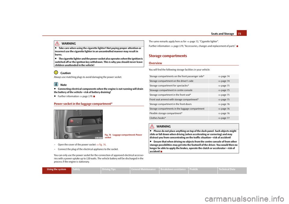
Power socket in the luggage compartment*– Open the cover of the power socket fig. 76 .
– Connect the plug of the electrical appliance to the socket.
You can only use the power socket for the connection of approved electrical accesso-
ries with a power uptake up to 120 watts. The vehicle battery will be discharged in the
process if the engine is stationary. The same remarks apply here as for
page 72, “Cigarette lighter”.
Further information page 179, “Accessories, changes and replacement of parts”.
Storage compartmentsOverviewYou will find the following storag e facilities in your vehicle:
WARNING
Please do not place anything on top of the dash panel. Such objects might
slide or fall down when driving (whe n accelerating or cornering) and may
distract you from concentrating on the traffic situation - risk of accident!
Ensure that when driving no objects from the centre console of from other
storage possibilities may get into the fo otwell of the driver. You would then no
longer be able to apply the brakes, oper ate the clutch or accelerator - risk of
accident!
Fig. 76 Luggage compartment: Power
socket
Storage compartments on the front passenger side*
page 74
Storage compartment on the driver's side
page 74
Storage compartment for spectacles*
page 75
Stowage compartment in centre console
page 75
Storage compartment in the front seat*
page 75
Front seat armrest with storage compartment*
page 75
Storage compartment in the front doors
page 76
Storage compartments in the luggage compartment
page 76
Flexible storage compartment*
page 76
Clothes hooks*
page 77
s16g.4.book Page 73 Wednesda y, February 10, 2010 3:53 PM
Page 76 of 231
Seats and Storage75
Using the system
Safety
Driving Tips
General Maintenance
Breakdown assistance
Praktik
Technical Data
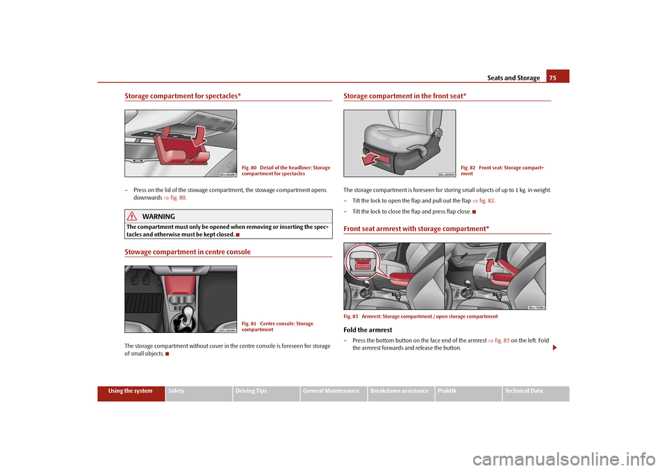
Storage compartment for spectacles*– Press on the lid of the stowage comp artment, the stowage compartment opens
downwards fig. 80 .
WARNING
The compartment must only be opened when removing or inserting the spec-
tacles and otherwise must be kept closed.Stowage compartment in centre consoleThe storage compartment without cover in the centre console is foreseen for storage
of small objects.
Storage compartment in the front seat*The storage compartment is foreseen for storing small objects of up to 1 kg. in weight.
– Tilt the lock to open the flap and pull out the flap fig. 82 .
– Tilt the lock to close the flap and press flap close.Front seat armrest with storage compartment*Fig. 83 Armrest: Storage compartment / open storage compartmentFold the armrest– Press the bottom button on the face end of the armrest fig. 83 on the left. Fold
the armrest forwards and release the button.
Fig. 80 Detail of the headliner: Storage
compartment for spectaclesFig. 81 Centre console: Storage
compartment
Fig. 82 Front seat: Storage compart-
ment
s16g.4.book Page 75 Wednesda y, February 10, 2010 3:53 PM
Page 77 of 231
Seats and Storage
76
Opening storage compartment
– Press the top button and fold up the cover of the storage compartment page 75,
fig. 83 on the right.
Note
The moving space of the arms can be restricted if the armrest is folded down. In city
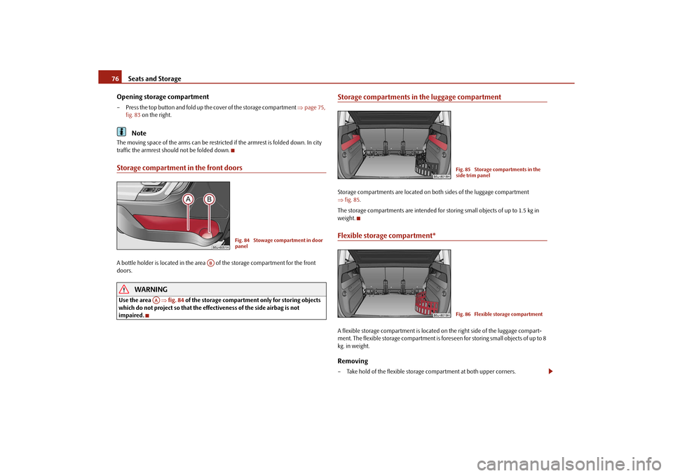
traffic the armrest should not be folded down.Storage compartment in the front doorsA bottle holder is located in the area of the storage compartment for the front
doors.
WARNING
Use the area fig. 84 of the storage compartment only for storing objects
which do not project so that the effectiveness of the side airbag is not
impaired.
Storage compartments in the luggage compartmentStorage compartments are located on bo th sides of the luggage compartment
fig. 85 .
The storage compartments are intended for storing small objects of up to 1.5 kg in
weight.Flexible storage compartment*A flexible storage compartmen t is located on the right side of the luggage compart-
ment. The flexible storage compartment is foreseen for storing small objects of up to 8
kg. in weight.Removing– Take hold of the flexible storage compartment at both upper corners.
Fig. 84 Stowage compartment in door
panel
AB
AA
Fig. 85 Storage compartments in the
side trim panelFig. 86 Flexible storage compartment
s16g.4.book Page 76 Wednesda y, February 10, 2010 3:53 PM
Page 78 of 231
Seats and Storage77
Using the system
Safety
Driving Tips
General Maintenance
Breakdown assistance
Praktik
Technical Data
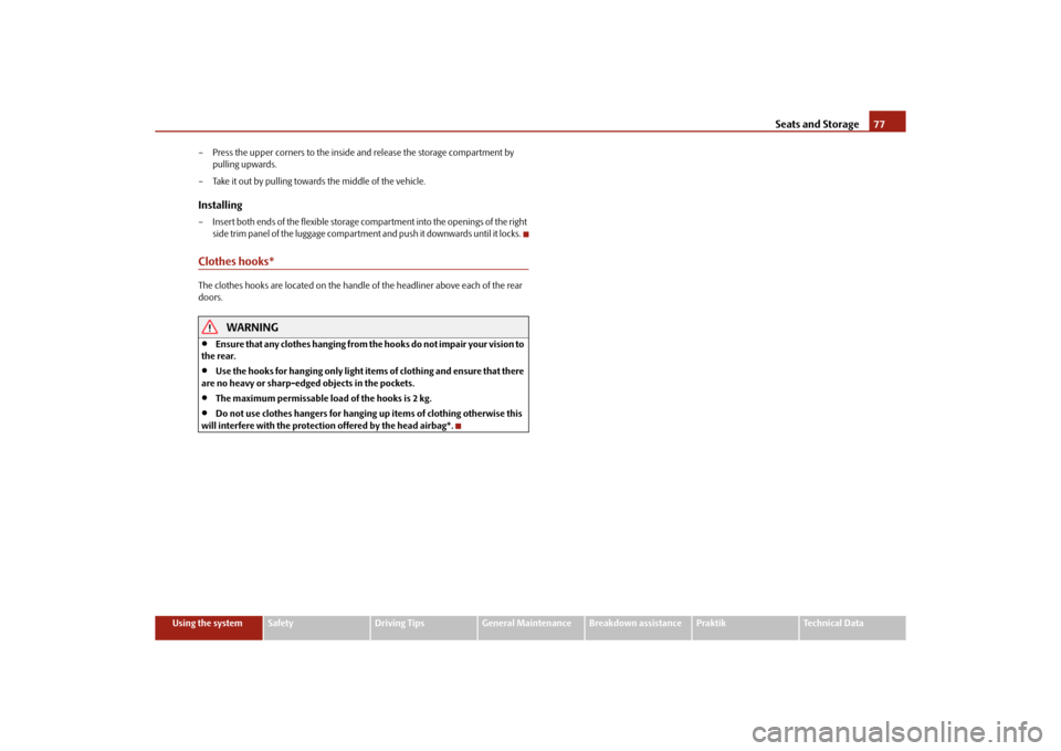
– Press the upper corners to the inside
and release the storage compartment by
pulling upwards.
– Take it out by pulling toward s the middle of the vehicle.
Installing– Insert both ends of the flexible storage compartment into the openings of the right
side trim panel of the luggage compartment and push it downwards until it locks.Clothes hooks*The clothes hooks are located on the handle of the headliner above each of the rear
doors.
WARNING
Ensure that any clothes hanging from the hooks do not impair your vision to
the rear.
Use the hooks for hanging only light item s of clothing and ensure that there
are no heavy or sharp-edge d objects in the pockets.
The maximum permissable load of the hooks is 2 kg.
Do not use clothes hangers for hanging up items of clothing otherwise this
will interfere with the protection offered by the head airbag*.
s16g.4.book Page 77 Wednesda y, February 10, 2010 3:53 PM
Page 80 of 231
Heating and air conditioning system79
Using the system
Safety
Driving Tips
General Maintenance
Breakdown assistance
Praktik
Technical Data
HeatingUsing the system
The heating system delivers air into the interior of the vehicle and
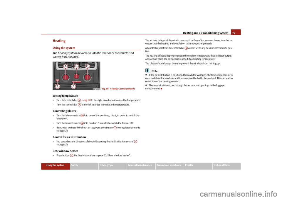
warms it as required.Setting temperature– Turn the control dial fig. 88 to the right in order to increase the temperature.
– Turn the control dial to the left in order to increase the temperature.Controlling blower– Turn the blower switch into one of the po sitions, 1 to 4, in order to switch the
blower on.
– Turn the blower switch into position 0 in order to switch the blower off.
– If you wish to shut off the fresh air supply , use the button - recirculated air mode
page 78.Control for air distribution– You can adjust the direction of the air flow using the air distribution control
page 78.Rear window heater– Press button . Further information page 52, “Rear window heater”. The air inlet in front of the windscreen must be free of ice, snow or leaves in order to
ensure that the heating and ventilation systems operate properly.
All controls apart from the control dial
can be set to any desired intermediate posi-
tion.
The heating effect is dependent upon the c oolant temperature, thus full heat output
only occurs when the engine has reached its operating temperature.
The blower should aways be on to prevent the windows from misting up.
Note
If the air distribution is positioned toward s the windows, the total amount of air is
used to defrost the windows and thus no air will be fed to the footwell. This can lead to
restriction of the heating comfort.
The used air streams out through the air removal openings in the luggage
compartment.
Fig. 88 Heating: Control elements
AAAAABAB
A1
AC
A2
AB
s16g.4.book Page 79 Wednesda y, February 10, 2010 3:53 PM
Page 88 of 231
Starting-off and Driving87
Using the system
Safety
Driving Tips
General Maintenance
Breakdown assistance
Praktik
Technical Data
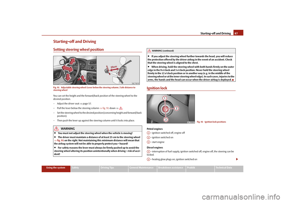
Starting-off and DrivingSetting steering wheel positionFig. 91 Adjustable steering wheel: Lever be low the steering column / Safe distance to
steering wheelYou can set the height and the forward/back position of the steering wheel to the
desired position.
– Adjust the driver seat page 57.
– Pull the lever below the steering column fig. 91 down .
– Set the steering wheel to the desired position (concerning height and forward/back position).
– Then push the lever up against the steering column until it locks into place.
WARNING
You must not adjust the steering wheel when the vehicle is moving!
The driver must maintain a distance of at least 25 cm to the steering wheel
fig. 91 on the right. Not maintaining this minimum distance will mean that
the airbag system will not be able to properly protect you - hazard!
For safety reasons the lever must always be firmly pushed up to avoid the
steering wheel altering its po sition unintentionally when driving - risk of acci-
dent!
If you adjust the steering wheel furthe r towards the head, you will reduce
the protection offered by the driver airbag in the event of an accident. Check
that the steering wheel is aligned to the chest.
When driving, hold the steering wheel with both hands firmly on the outer
edge in the 9 o'clock and 3 o'clock position. Never hold the steering wheel
firmly in the 12 o'clock position or in another way (e.g. in the middle of the
steering wheel or at the inne r steering wheel edge). In such cases, injuries to the
arms, the hands and the head can occur when the driver airbag is deployed.
Ignition lockPetrol engines
- ignition switched off, engine off
- ignition switched on
- start engine
Diesel engines - interruption of fuel supply, ignition swit ched off, engine off, the steering can be
locked.
- heating glow plugs on, ignition switched on
WARNING (continued)
Fig. 92 Ignition lock positions
A1A2A3A1A2
s16g.4.book Page 87 Wednesda y, February 10, 2010 3:53 PM