fold seats SKODA SUPERB 2014 2.G / (B6/3T) User Guide
[x] Cancel search | Manufacturer: SKODA, Model Year: 2014, Model line: SUPERB, Model: SKODA SUPERB 2014 2.G / (B6/3T)Pages: 246, PDF Size: 17.16 MB
Page 101 of 246
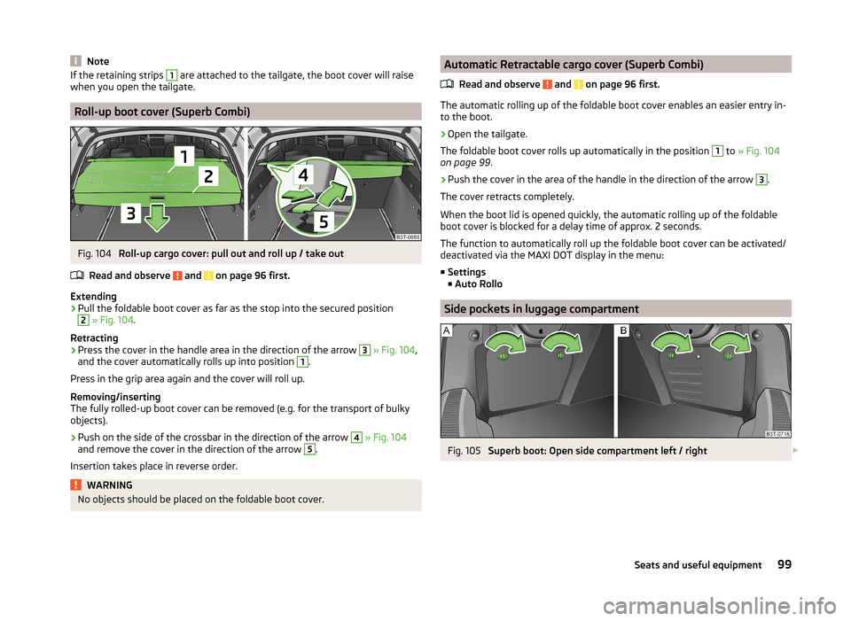
NoteIf the retaining strips 1 are attached to the tailgate, the boot cover will raise
when you open the tailgate.
Roll-up boot cover (Superb Combi)
Fig. 104
Roll-up cargo cover: pull out and roll up / take out
Read and observe
and on page 96 first.
Extending
›
Pull the foldable boot cover as far as the stop into the secured position
2
» Fig. 104 .
Retracting
›
Press the cover in the handle area in the direction of the arrow
3
» Fig. 104 ,
and the cover automatically rolls up into position
1
.
Press in the grip area again and the cover will roll up.
Removing/inserting
The fully rolled-up boot cover can be removed (e.g. for the transport of bulky objects).
›
Push on the side of the crossbar in the direction of the arrow
4
» Fig. 104
and remove the cover in the direction of the arrow
5
.
Insertion takes place in reverse order.
WARNINGNo objects should be placed on the foldable boot cover.Automatic Retractable cargo cover (Superb Combi)
Read and observe
and on page 96 first.
The automatic rolling up of the foldable boot cover enables an easier entry in-to the boot.
›
Open the tailgate.
The foldable boot cover rolls up automatically in the position
1
to » Fig. 104
on page 99 .
›
Push the cover in the area of the handle in the direction of the arrow
3
.
The cover retracts completely.
When the boot lid is opened quickly, the automatic rolling up of the foldable
boot cover is blocked for a delay time of approx. 2 seconds.
The function to automatically roll up the foldable boot cover can be activated/
deactivated via the MAXI DOT display in the menu:
■ Settings
■ Auto Rollo
Side pockets in luggage compartment
Fig. 105
Superb boot: Open side compartment left / right
99Seats and useful equipment
Page 105 of 246
WARNINGEnsure that the carrier rails and variable loading floor are correctly fastened
when installing the variable loading floor. If this is not the case, there is a
risk of injury for the occupants.
Extending variable loading floor with integrated aluminium rails
and faseting elements (Superb Combi)
Introduction
This chapter contains information on the following subjects:
Partial extension of variable load floor
103
Divide boot
103
Fit and remove variable loading floor
104
Fixing set
104
Movable lashing eyes
105
The variable loading floor makes handling of bulky items of luggage easier.
CAUTION
The maximum permissible load of the variable loading floor is 75 kg.
Note
The space below the variable loading floor can be used for stowing objects, for
example the fastening elements, removed foldable boot cover, etc.
Partial extension of variable load floor
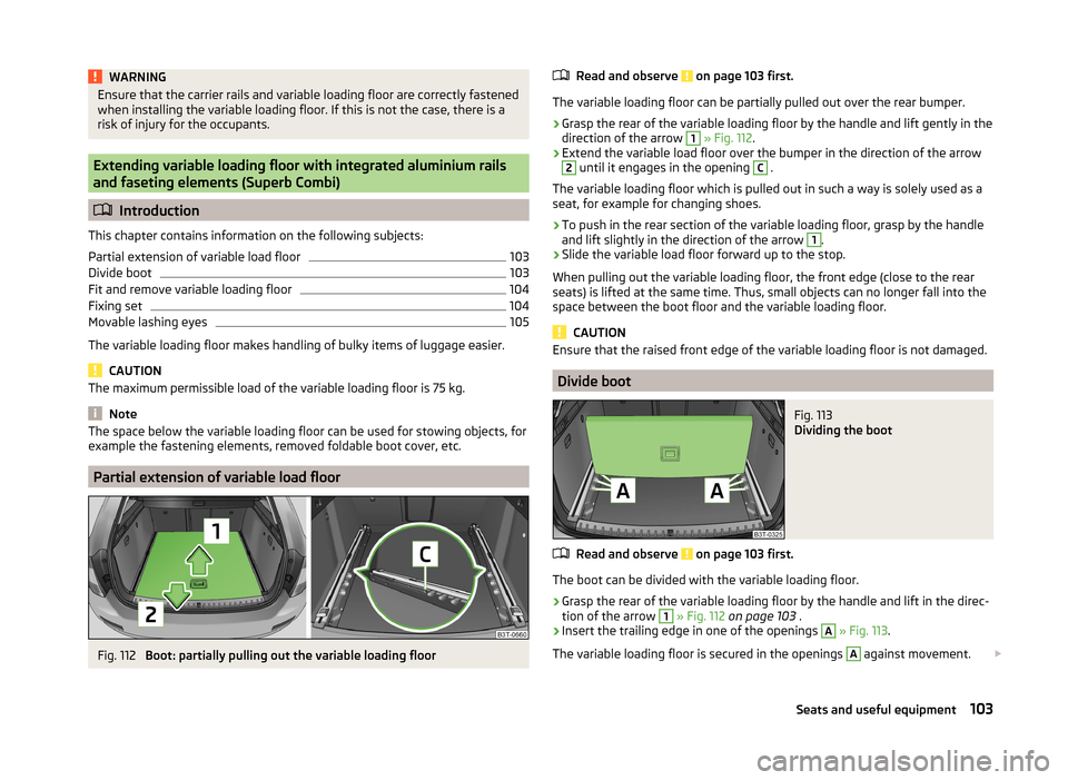
Fig. 112
Boot: partially pulling out the variable loading floor
Read and observe on page 103 first.
The variable loading floor can be partially pulled out over the rear bumper.
›
Grasp the rear of the variable loading floor by the handle and lift gently in the
direction of the arrow
1
» Fig. 112 .
›
Extend the variable load floor over the bumper in the direction of the arrow
2
until it engages in the opening
C
.
The variable loading floor which is pulled out in such a way is solely used as a
seat, for example for changing shoes.
›
To push in the rear section of the variable loading floor, grasp by the handle
and lift slightly in the direction of the arrow
1
.
›
Slide the variable load floor forward up to the stop.
When pulling out the variable loading floor, the front edge (close to the rear
seats) is lifted at the same time. Thus, small objects can no longer fall into the
space between the boot floor and the variable loading floor.
CAUTION
Ensure that the raised front edge of the variable loading floor is not damaged.
Divide boot
Fig. 113
Dividing the boot
Read and observe on page 103 first.
The boot can be divided with the variable loading floor.
›
Grasp the rear of the variable loading floor by the handle and lift in the direc-
tion of the arrow
1
» Fig. 112 on page 103 .
›
Insert the trailing edge in one of the openings
A
» Fig. 113 .
The variable loading floor is secured in the openings
A
against movement.
103Seats and useful equipment
Page 106 of 246
The variable loading floor can be pulled out a little more before dividing the
boot with the variable loading floor » page 103. This enlarges the space be-
tween the rear seats and the separation.
CAUTION
Ensure that the raised front edge of the variable loading floor is not damaged.
Fit and remove variable loading floor
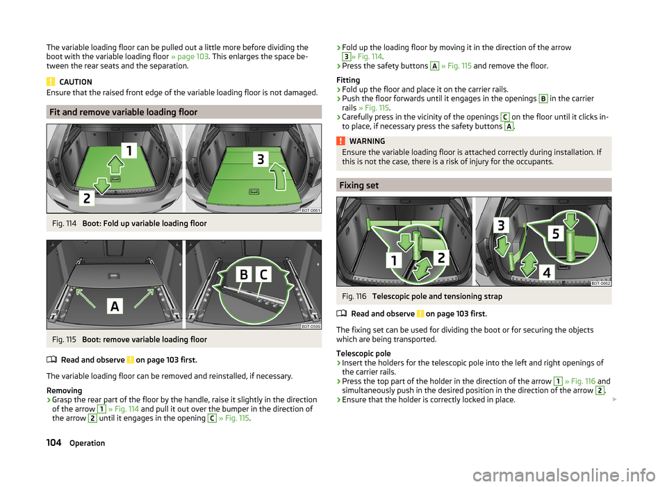
Fig. 114
Boot: Fold up variable loading floor
Fig. 115
Boot: remove variable loading floor
Read and observe
on page 103 first.
The variable loading floor can be removed and reinstalled, if necessary.
Removing
›
Grasp the rear part of the floor by the handle, raise it slightly in the direction
of the arrow
1
» Fig. 114 and pull it out over the bumper in the direction of
the arrow
2
until it engages in the opening
C
» Fig. 115 .
›Fold up the loading floor by moving it in the direction of the arrow3» Fig. 114
.›
Press the safety buttons
A
» Fig. 115 and remove the floor.
Fitting
›
Fold up the floor and place it on the carrier rails.
›
Push the floor forwards until it engages in the openings
B
in the carrier
rails » Fig. 115 .
›
Carefully press in the vicinity of the openings
C
on the floor until it clicks in-
to place, if necessary press the safety buttons
A
.
WARNINGEnsure the variable loading floor is attached correctly during installation. If
this is not the case, there is a risk of injury for the occupants.
Fixing set
Fig. 116
Telescopic pole and tensioning strap
Read and observe
on page 103 first.
The fixing set can be used for dividing the boot or for securing the objects
which are being transported.
Telescopic pole
›
Insert the holders for the telescopic pole into the left and right openings of
the carrier rails.
›
Press the top part of the holder in the direction of the arrow
1
» Fig. 116 and
simultaneously push in the desired position in the direction of the arrow
2
.
›
Ensure that the holder is correctly locked in place.
104Operation
Page 107 of 246
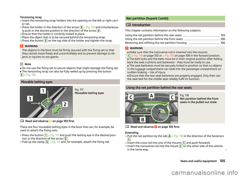
Tensioning strap›Insert the tensioning strap holders into the opening on the left or right carri-
er rail.›
Press the holder in the direction of the arrow
3
» Fig. 116 and simultaneous-
ly push in the desired position in the direction of the arrow
4
.
›
Ensure that the holder is correctly locked in place.
›
Place the object that is to be secured behind the tensioning strap.
›
Press the button
5
on the top side of the holder and tighten the strap.
WARNINGThe objects in the boot must be firmly secured with the fixing set so that
they cannot move freely and uncontrollably and to prevent damage to ob-
jects or injuries to occupants.
Note
■ Do not use the fixing set to secure objects that might damage the fixing set.■The tensioning strap can also be fully reeled up by pressing the button5
» Fig. 116 .
Movable lashing eyes
Fig. 117
Moveable lashing eyes
Read and observe on page 103 first.
There are four moveable lashing eyes in the boot that can, for example, be
used to attach the fixing nets.
›
Press the button
1
» Fig. 117 and push the lashing eye in the desired posi-
tion in the direction of the arrow
2
.
›
Fold up the clamp
3
» Fig. 117 and, for example, attach the fixing net.
Net partition (Superb Combi)
Introduction
This chapter contains information on the following subjects:
Using the net partition behind the rear seats
105
Using the net partition behind the front seats
106
Removing and refitting the net partition housing
106WARNING■ Make sure that the transverse rod is inserted into the mountsC » Fig. 118 on page 105 or » Fig. 119 on page 106 in the forward position.■
The belt locks and the belts must be in their original position after folding
back the seat cushions and backrests - they must be ready to use.
■
The seat backrests must be securely locked in position so that no objects
in the luggage compartment can slide into the passenger compartment on
sudden braking – risk of injury.
■
Ensure that the rear seat backrests are properly engaged. Only then can
the seat belt for the middle seat reliably fulfil its function.
Using the net partition behind the rear seats
Fig. 118
Net partition behind the front
seats in the pulled-out state
Read and observe on page 105 first.
Extending
›
Pull the net partition by the tab
A
» Fig. 118 in the direction of the fasteners
C
.
›
Insert the cross rod into one of the mounts
C
and push forwards.
›
Insert the transverse rod into the mount
C
on the other side of the vehicle
in the same way.
105Seats and useful equipment
Page 108 of 246
Retracting›Pull the transverse rod back slightly first on one side and then on the other
and remove it from the mounts C
» Fig. 118 .
›
Hold the cross rod in such a way that the net partition can slowly roll up into
the housing
B
without being damaged.
Note
If you wish to use the entire luggage compartment, the roll-up luggage com-
partment cover can be removed » page 99.
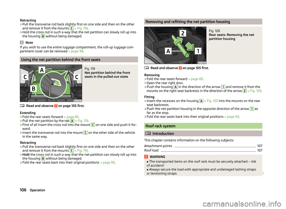
Using the net partition behind the front seats
Fig. 119
Net partition behind the front
seats in the pulled-out state
Read and observe on page 105 first.
Extending
›
Fold the rear seats forward » page 85.
›
Pull the net partition by the tab
A
» Fig. 119 .
›
First of all insert the cross rod into the mount
C
on one side and push it for-
ward.
›
Insert the transverse rod into the mount
C
on the other side of the vehicle
in the same way.
Retracting
›
Pull the transverse rod back slightly first on one side and then on the other
and remove it from the mounts
C
» Fig. 119 .
›
Hold the cross rod in such a way that the net partition can slowly roll up into
the housing
B
without being damaged.
›
Fold the rear seats back into their original positions » page 85.
Removing and refitting the net partition housingFig. 120
Rear seats: Removing the net
partition housing
Read and observe on page 105 first.
Removing
›
Fold the rear seats forward » page 85.
›
Open the rear right door.
›
Push the housing
A
in the direction of the arrow
1
and remove it from the
mounts on the right seat backrests in the direction of the arrow
2
» Fig. 120 .
Fitting
›
Insert the recesses on the housing
A
» Fig. 120 into the mounts on the rear
seat backrests.
›
Push the net partition housing in the opposite direction of the arrow
1
as
far as the stop.
›
Fold the rear seats back into their original positions » page 85.
Roof rack system
Introduction
This chapter contains information on the following subjects:
Attachment points
107
Roof load
107WARNING■ The transported items on the roof rack must be securely attached – risk
of accident!■
Always secure the load with appropriate and undamaged lashing straps
or tensioning straps.
106Operation
Page 136 of 246
Ejecting all CDs›Press and hold the button A » Fig. 131 for more than 2 seconds. All CDs in
the CD-changer are ejected consecutively.
Note
■ Insert a CD, with the labelled side facing up, into the CD slot B » Fig. 131 until
it is automatically drawn in. The play function will start automatically.■
After loading a CD into the CD changer, wait until the indicator light of the
corresponding button
D
is illuminated. Then the CD case
B
is free to load the
next CD.
■
If a position is selected, on which a CD is already located, this CD is ejected.
Remove the ejected CD and load the desired CD.
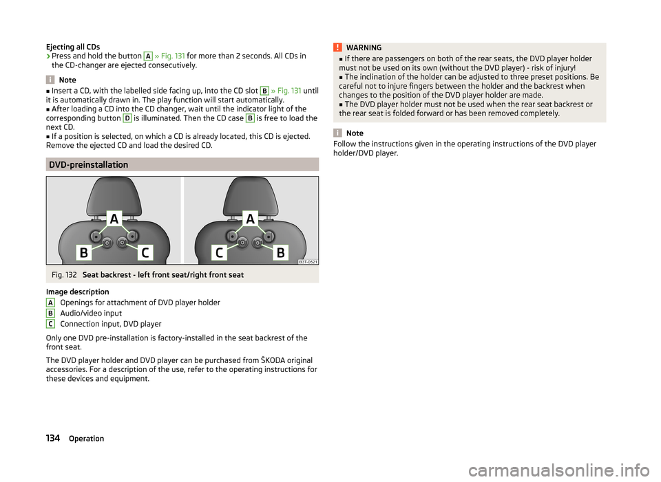
DVD-preinstallation
Fig. 132
Seat backrest - left front seat/right front seat
Image description Openings for attachment of DVD player holder
Audio/video input
Connection input, DVD player
Only one DVD pre-installation is factory-installed in the seat backrest of the
front seat.
The DVD player holder and DVD player can be purchased from ŠKODA original
accessories. For a description of the use, refer to the operating instructions for
these devices and equipment.
ABCWARNING■ If there are passengers on both of the rear seats, the DVD player holder
must not be used on its own (without the DVD player) - risk of injury!■
The inclination of the holder can be adjusted to three preset positions. Be
careful not to injure fingers between the holder and the backrest when
changes to the position of the DVD player holder are made.
■
The DVD player holder must not be used when the rear seat backrest or
the rear seat is folded forward or has been removed completely.
Note
Follow the instructions given in the operating instructions of the DVD player
holder/DVD player.134Operation
Page 217 of 246
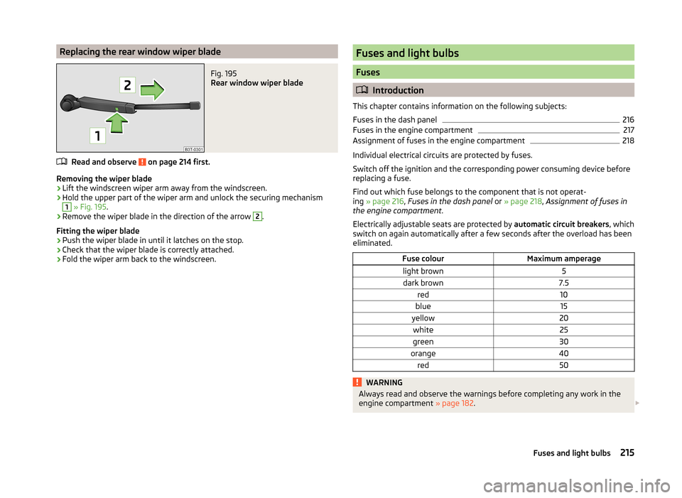
Replacing the rear window wiper bladeFig. 195
Rear window wiper blade
Read and observe on page 214 first.
Removing the wiper blade
›
Lift the windscreen wiper arm away from the windscreen.
›
Hold the upper part of the wiper arm and unlock the securing mechanism
1
» Fig. 195 .
›
Remove the wiper blade in the direction of the arrow
2
.
Fitting the wiper blade
›
Push the wiper blade in until it latches on the stop.
›
Check that the wiper blade is correctly attached.
›
Fold the wiper arm back to the windscreen.
Fuses and light bulbs
Fuses
Introduction
This chapter contains information on the following subjects:
Fuses in the dash panel
216
Fuses in the engine compartment
217
Assignment of fuses in the engine compartment
218
Individual electrical circuits are protected by fuses.
Switch off the ignition and the corresponding power consuming device before
replacing a fuse.
Find out which fuse belongs to the component that is not operat-
ing » page 216 , Fuses in the dash panel or » page 218 , Assignment of fuses in
the engine compartment .
Electrically adjustable seats are protected by automatic circuit breakers, which
switch on again automatically after a few seconds after the overload has been
eliminated.
Fuse colourMaximum amperagelight brown5dark brown7.5red10blue15yellow20white25green30orange40red50WARNINGAlways read and observe the warnings before completing any work in the
engine compartment » page 182. 215Fuses and light bulbs
Page 235 of 246
Folding hook97
Non-closable side pocket (Superb Combi)100
Removable Light (Superb Combi)101
Roll-up boot cover (Superb Combi)99
Side compartment with battery100
Boot cover (Superb Combi)99
Boot lid55
automatic locking56
Warning light34
(Superb Combi)56
Brake Information messages
33
Warning light33
Brake booster141
Brake fluid189
Changing189
Checking189
Information messages33
Brake pads warning light
38
Brakes Brake assist systems
151
Brake booster141
Brake fluid189
Handbrake141
Running in145
Braking Information on braking
140
Breakdown kit205
Break recommendation See Fatigue detection
162
Bulbs Replacing
219
Button in the driver's door Electric power windows
59
C
Car care
169
Car computer See multifunction display
41
Car park ticket holder87
Carrier106
Cavity protection176
CD changer133
Central locking48
Central locking button52
Changing Brake fluid
189
Engine oil187
Wheels201
Changing a wheel Follow-up work
202
Preliminary work202
Remove and attaching a wheel202
Charging a vehicle battery192
Check Fit ball head properly
165
Checking Battery electrolyte level
191
Brake fluid189
Coolant188
Engine oil186
Oil level186
Windscreen washer fluid184
Children and safety21
Child safety Side airbag
22
Child safety lock53
Child seat Classification
23
ISOFIX23
on the front passenger seat21
TOP TETHER24
Use of child seats23
Use of ISOFIX child seats24
Chrome parts refer to Taking care of your vehicle
174
Cigarette lighter89
Cleaning169
Alcantara178
Artificial leather178
cloths178
Covers of electrically heated seats178
Headlight lenses175
Natural leather177
Plastic parts174
Wheels176
Climatronic113
Air recirculation115
automatic mode114
Control elements113
Controlling blower116
Cooling system114
Defrosting windscreen116
Setting the temperature114
Clothes hook92
Cockpit 12-Volt power outlet
90
Ashtray89
Cigarette lighter89
General view27
Lighting71
Practical equipment86
Storage compartments86
Comfort control window
61
COMING HOME70
Compartments86
Computer See multifunction display
41
Convenience operation sliding / tilting roof
63
sliding / tilting roof (Superb Estate)65
convenience turn signal67
Coolant187
Checking188
Information messages34
Replenishing188
233Index
Page 240 of 246
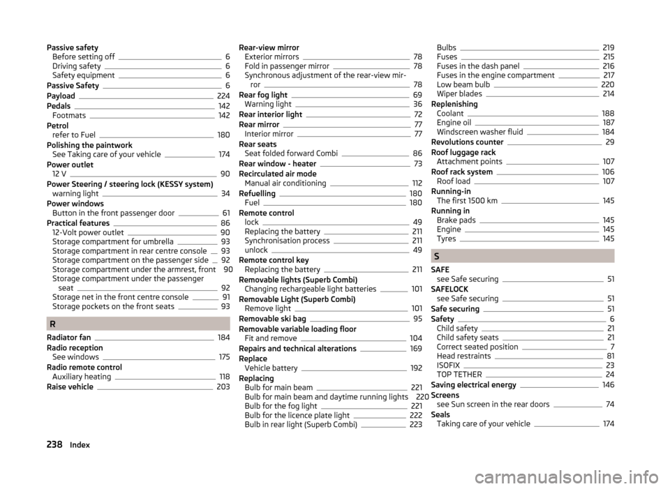
Passive safetyBefore setting off6
Driving safety6
Safety equipment6
Passive Safety6
Payload224
Pedals142
Footmats142
Petrol refer to Fuel
180
Polishing the paintwork See Taking care of your vehicle
174
Power outlet 12 V
90
Power Steering / steering lock (KESSY system) warning light
34
Power windows Button in the front passenger door
61
Practical features86
12-Volt power outlet90
Storage compartment for umbrella93
Storage compartment in rear centre console93
Storage compartment on the passenger side92
Storage compartment under the armrest, front 90
Storage compartment under the passenger seat
92
Storage net in the front centre console91
Storage pockets on the front seats93
R
Radiator fan
184
Radio reception See windows
175
Radio remote control Auxiliary heating
118
Raise vehicle203
Rear-view mirror Exterior mirrors78
Fold in passenger mirror78
Synchronous adjustment of the rear-view mir- ror
78
Rear fog light69
Warning light36
Rear interior light72
Rear mirror77
Interior mirror77
Rear seats Seat folded forward Combi
86
Rear window - heater73
Recirculated air mode Manual air conditioning
112
Refuelling180
Fuel180
Remote control lock
49
Replacing the battery211
Synchronisation process211
unlock49
Remote control key Replacing the battery
211
Removable lights (Superb Combi) Changing rechargeable light batteries
101
Removable Light (Superb Combi) Remove light
101
Removable ski bag95
Removable variable loading floor Fit and remove
104
Repairs and technical alterations169
Replace Vehicle battery
192
Replacing Bulb for main beam
221
Bulb for main beam and daytime running lights 220
Bulb for the fog light
221
Bulb for the licence plate light222
Bulb in rear light (Superb Combi)223
Bulbs219
Fuses215
Fuses in the dash panel216
Fuses in the engine compartment217
Low beam bulb220
Wiper blades214
Replenishing Coolant
188
Engine oil187
Windscreen washer fluid184
Revolutions counter29
Roof luggage rack Attachment points
107
Roof rack system106
Roof load107
Running-in The first 1500 km
145
Running in Brake pads
145
Engine145
Tyres145
S
SAFE see Safe securing
51
SAFELOCK see Safe securing
51
Safe securing51
Safety6
Child safety21
Child safety seats21
Correct seated position7
Head restraints81
ISOFIX23
TOP TETHER24
Saving electrical energy146
Screens see Sun screen in the rear doors
74
Seals Taking care of your vehicle
174
238Index