wheel SKODA SUPERB 2014 2.G / (B6/3T) User Guide
[x] Cancel search | Manufacturer: SKODA, Model Year: 2014, Model line: SUPERB, Model: SKODA SUPERB 2014 2.G / (B6/3T)Pages: 246, PDF Size: 17.16 MB
Page 44 of 246
Note■In certain national versions the displays appear in the Imperial system of
measures.■
If the display of the second speed is activated in mph, the current speed is
not indicated in km/h on the display.
■
The amount of fuel consumed will not be indicated.
Memory
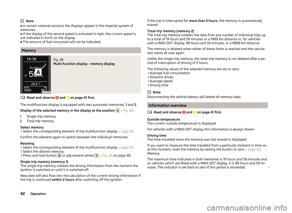
Fig. 28
Multi-function display - memory display
Read and observe and on page 41 first.
The multifunction display is equipped with two automatic memories, 1 and 2.
Display of the selected memory in the display at the position
A
» Fig. 28 .
Single-trip memory
Total trip memory
Select memory
›
Select the corresponding element of the multifunction display » page 42.
Confirm the element again to switch between the individual memories.
Reseting
›
Select the corresponding element of the multifunction display » page 42.
›
Select the desired memory.
›
Press and hold button
B
or adjustment wheel
D
» Fig. 26 on page 40 .
Single-trip memory (memory 1)
The single-trip memory collates the driving information from the moment the
ignition is switched on until it is switched off.
New data will also flow into the calculation of the current driving information if the trip is continued within 2 hours after switching off the ignition.
If the trip is interrupted for more than 2 hours, the memory is automatically
erased.
Total-trip memory (memory 2)
The total trip memory collates the data from any number of individual trips up
to a total of 19 hours and 59 minutes or a 1999 km distance or, for vehicles
with a MAXI DOT display, 99 hours and 59 minutes, or a 9999 km distance.
The memory is deleted when either of these limits is reached and the calcula-
tion starts all over again.
Unlike the single-trip memory, the total-trip memory is not deleted after a pe-
riod of interruption of driving of 2 hours.
The following values of the selected memory are set to zero.
› Average fuel consumption.
› Distance driven.
› Average speed.
› Driving time
Note
Disconnecting the vehicle battery will delete all memory data.
Information overview
Read and observe
and on page 41 first.
Outside temperature
The current outside temperature is displayed.
For vehicles with a MAXI DOT display this information is always shown.
Driving time
The time travelled since the memory was last erased is displayed.
If you want to measure the time travelled from a particular moment in time on,
at this moment, reset the memory by setting the button to zero » page 42,
Memory .
The maximum time indicated in both memories is 19 hours and 59 minutes and
on vehicles which are fitted with a MAXI DOT display, it is 99 hours and 59 mi-
nutes. The indicator is set back to zero if this period is exceeded.
42Operation
Page 69 of 246
Daylight running lights (DAY LIGHT)Read and observe
on page 65 first.
The daytime running lights (the only function) provides the lighting of the frontvehicle range.
The daytime running lights are switched on automatically if the following
conditions are met:
The light switch is in the position
or
» Fig. 48 on page 66 .
The ignition is switched on.
The parking aid is activated.
Deactivating the function
›
Switch off the ignition.
›
Pull the turning signal and main beam lever ( » Fig. 49 on page 67 ) towards
the steering wheel, push down and hold in this position.
›
Switch on the ignition.
›
Hold the lever in this position for at least 3 seconds after switching on the
ignition.
Activating the function
›
Switch off the ignition.
›
Pull the turning signal and main beam lever towards the steering wheel,
push it up and hold it in this position.
›
Switch on the ignition.
›
Hold the lever in this position for at least 3 seconds after switching on the
ignition.
On vehicles with MAXI DOT display, the function can be enabled or disabled in
the menu item Dayl. dri. light » page 45 .
WARNINGWhen the daytime running light is switched on, the side lights (neither at
the front or rear) and the number plate lights are not lit. Therefore always
switch on the low beam when the visibility is poor.Turn signal and main beamFig. 49
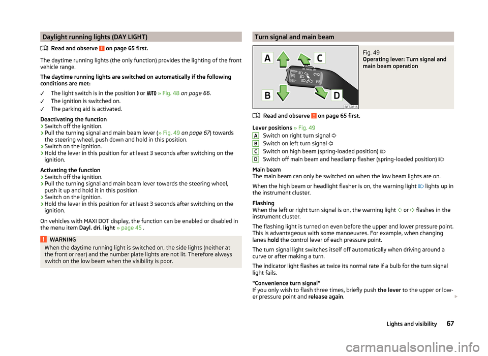
Operating lever: Turn signal and
main beam operation
Read and observe on page 65 first.
Lever positions » Fig. 49
Switch on right turn signal
Switch on left turn signal
Switch on high beam (spring-loaded position)
Switch off main beam and headlamp flasher (spring-loaded position)
Main beam
The main beam can only be switched on when the low beam lights are on.
When the high beam or headlight flasher is on, the warning light lights up in
the instrument cluster.
Flashing
When the left or right turn signal is on, the warning light or
flashes in the
instrument cluster.
The flashing light is turned on even before the upper and lower pressure point.
This is advantageous with some manoeuvres. For example, when changing
lanes hold the control lever of each pressure point.
The turn signal light switches itself off automatically when driving around a
curve or after making a turn.
The indicator light flashes at twice its normal rate if a bulb for the turn signal
light fails.
“Convenience turn signal”
If you only wish to flash three times, briefly push the lever to the upper or low-
er pressure point and release again.
ABCD67Lights and visibility
Page 71 of 246
Dynamic cornering lights
The cone of light in front of the vehicle is adjusted to the steering angle so
that the road in the curve is illuminated. This function is active at speeds
greater than 10 km.h and in all AFS modes.
Tourist lights (Travel mode)
This mode makes it possible to drive in countries with opposing traffic system
(driving on the left/right) without dazzling the oncoming vehicles.
When this mode is active, the above-mentioned modes and the side swivel of
the headlights is deactivated.
This mode can be enabled or disabled via the Maxi DOT display in the Travel
mode » page 45 , Lights and Visibility menu option.WARNINGIf the AFS system is defective, the headlights are automatically lowered to
the emergency position, which prevents a possible dazzling of oncoming
traffic. This reduces the cone of light in front of the vehicle. Drive carefully
and visit a specialist garage as soon as possible.
Note
When the “tourist light” mode is active, the warning light flashes for 10 sec-
onds each time the ignition is switched on.
Fog lights
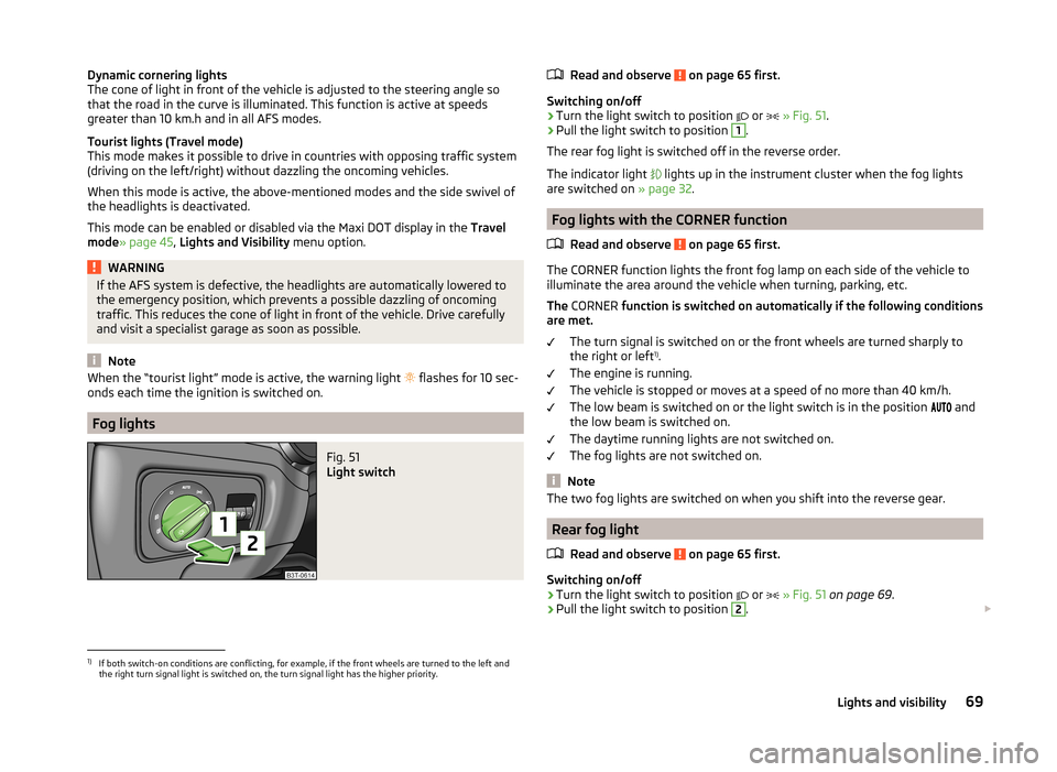
Fig. 51
Light switch
Read and observe on page 65 first.
Switching on/off
›
Turn the light switch to position
or
» Fig. 51 .
›
Pull the light switch to position
1
.
The rear fog light is switched off in the reverse order.
The indicator light
lights up in the instrument cluster when the fog lights
are switched on » page 32.
Fog lights with the CORNER function
Read and observe
on page 65 first.
The CORNER function lights the front fog lamp on each side of the vehicle to
illuminate the area around the vehicle when turning, parking, etc.
The CORNER function is switched on automatically if the following conditions
are met.
The turn signal is switched on or the front wheels are turned sharply to
the right or left 1)
.
The engine is running.
The vehicle is stopped or moves at a speed of no more than 40 km/h.
The low beam is switched on or the light switch is in the position and
the low beam is switched on.
The daytime running lights are not switched on.
The fog lights are not switched on.
Note
The two fog lights are switched on when you shift into the reverse gear.
Rear fog light
Read and observe
on page 65 first.
Switching on/off
›
Turn the light switch to position or
» Fig. 51 on page 69 .
›
Pull the light switch to position
2
.
1)
If both switch-on conditions are conflicting, for example, if the front wheels are turned to the left and
the right turn signal light is switched on, the turn signal light has the higher priority.
69Lights and visibility
Page 81 of 246
CAUTION■The exterior mirrors with fold-in function never mechanically fold by hand
- there is a risk of damaging the electric mirror actuator!■
When the mirror is swung by external influences (due to impact during ma-
noeuvring, for example), then first fold-in the mirror by turning the knob and
wait for a loud clapping noise.
Note
■ The mirror heater only operates when the engine is running and up to an
outside temperature of +35 ℃.■
If the electrical mirror setting fails at any time, the mirrors can be adjusted by
hand by pressing on the edge of the mirror surface.
Seats and useful equipment
Adjusting the seats
Introduction
This chapter contains information on the following subjects:
Manually adjusting the front seats
80
Electric front seat adjustment
80
Head restraints
81
Memory function of the electrically adjustable seat
82
Memory function of the remote control key
82
The driver's seat should be adjusted in such a way that the pedals can be fully
pressed to the floor with slightly bent legs.
The seat backrest on the driver's seat should be adjusted in such a way that the upper point of the steering wheel can be easily reached with slightly bent
arms.
Correct adjustment of the seats is particularly important for the following rea-
sons.
› Reaching the controls safely and quickly.
› A relaxed and fatigue-free body position.
› Achieving the maximum protection offered by the seat belts and the airbag
system.
WARNING■ Only adjust the driver's seat when the vehicle is stationary – risk of acci-
dent!■
Caution when adjusting the seat! You may suffer injuries or bruises as a
result of adjusting the seat without paying proper attention.
■
The electric front seat adjustment is still functional if the ignition is
switched off (even with the ignition key removed). Therefore, when leaving
the vehicle, never leave people who are not completely independent, such
as children, unattended in the vehicle - there is a danger of injury!
■
Never carry more people than the number of seats in the vehicle.
■
Do not carry any objects on the front passenger seat except objects de-
signed for this purpose (e.g. child seats) – risk of accident!
79Seats and useful equipment
Page 82 of 246
Note■After a certain time, play can develop within the adjustment mechanism of
the backrest angle.■
For safety reasons, it is not possible to store the seat position in the electric
seat memory and remote control key memory if the inclination angle of the
seat backrest is more than 102° in relation to the seat cushion.
■
Each time you store the position of the electrically adjustable driver's seat
and exterior mirrors, the existing setting is deleted.
Manually adjusting the front seats
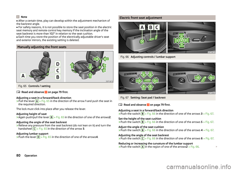
Fig. 65
Controls / setting
Read and observe
on page 79 first.
Adjusting a seat in a forward/back direction
›
Pull the lever
A
» Fig. 65 in the direction of the arrow 1 and push the seat in
the required direction.
The lock must click into place after you release the lever.
Adjusting height of seat
›
Again push/pull the lever
B
» Fig. 65 in the direction of one of the arrows 2.
Adjusting the angle of the seat backrest
›
Relieve any pressure from the seat backrest (do not lean on it) and turn the
handwheel
C
» Fig. 65 in the direction of the arrow 3.
Adjusting lumbar support
›
Push the lever
D
» Fig. 65 in the direction of one of the arrows 4.
Electric front seat adjustmentFig. 66
Adjusting controls / lumbar support
Fig. 67
Setting: Seat pad / backrest
Read and observe
on page 79 first.
Adjusting a seat in a forward/back direction
›
Push the switch
B
» Fig. 66 in the direction of one of the arrows 3 » Fig. 67 .
Set the height of the seat cushion
›
Push the switch
B
» Fig. 66 in the direction of one of the arrows 5 » Fig. 67 .
Adjust the angle of the seat cushion
›
Push the switch
B
» Fig. 66 in the direction of one of the arrows 4 » Fig. 67 .
Adjusting the angle of the seat backrest
›
Push the switch
C
» Fig. 66 in the direction of one of the arrows 6 » Fig. 67 .
Reducing or increasing the curvature of the lumbar support
›
Push the switch
A
in the region of one of the arrows 2 » Fig. 66 .
80Operation
Page 100 of 246
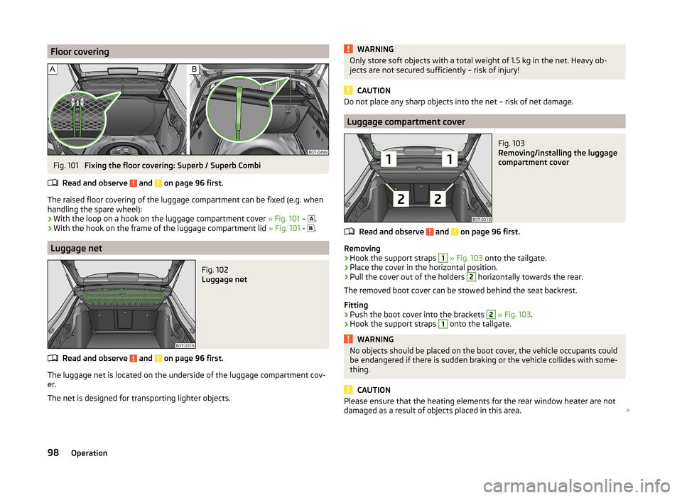
Floor coveringFig. 101
Fixing the floor covering: Superb / Superb Combi
Read and observe
and on page 96 first.
The raised floor covering of the luggage compartment can be fixed (e.g. when
handling the spare wheel):
› With the loop on a hook on the luggage compartment cover
» Fig. 101 –
.
› With the hook on the frame of the luggage compartment lid
» Fig. 101 -
.
Luggage net
Fig. 102
Luggage net
Read and observe and on page 96 first.
The luggage net is located on the underside of the luggage compartment cov-
er.
The net is designed for transporting lighter objects.
WARNINGOnly store soft objects with a total weight of 1.5 kg in the net. Heavy ob-
jects are not secured sufficiently – risk of injury!
CAUTION
Do not place any sharp objects into the net – risk of net damage.
Luggage compartment cover
Fig. 103
Removing/installing the luggage
compartment cover
Read and observe and on page 96 first.
Removing
›
Hook the support straps
1
» Fig. 103 onto the tailgate.
›
Place the cover in the horizontal position.
›
Pull the cover out of the holders
2
horizontally towards the rear.
The removed boot cover can be stowed behind the seat backrest.
Fitting
›
Push the boot cover into the brackets
2
» Fig. 103 .
›
Hook the support straps
1
onto the tailgate.
WARNINGNo objects should be placed on the boot cover, the vehicle occupants could
be endangered if there is sudden braking or the vehicle collides with some-
thing.
CAUTION
Please ensure that the heating elements for the rear window heater are not
damaged as a result of objects placed in this area. 98Operation
Page 121 of 246
Display warning light B » Fig. 127ImportanceLights up orange for around 2 sec-
onds, then flashes green or red.The battery is weak, however the
switching on or off signal was not re-
ceived.Flashes orange for around 5 seconds.The battery is discharged, however
the switching on or off signal was not
received.
Replace the battery » page 211.
CAUTION
The radio remote control comprises electronic components and must therefore
be protected against water, severe impacts and direct sunlight.Communication and multimedia
General information
Introduction
This chapter contains information on the following subjects:
Mobile phones and two-way radio systems
119
Universal telephone preinstallation (hands free)
120
Operating the phone on the multifunction steering wheel
120
Symbols in the MAXI DOT display
121
Phone Phonebook
121
Mobile phones and two-way radio systems
ŠKODA permits the operation of mobile phones and two-way radio systems
with a professionally installed external aerial and a maximum transmission
power of up to 10 watts.
Please ask at a specialist workshop about installing and operating mobile
phones and two-way radio systems that have a transmission power of more
than 10 W.
Operating mobile phones or two-way radio systems may interfere with the
functionality of the electronic systems in your vehicle.
This could be for the following reasons.
› no external aerial.
› external aerial incorrectly installed.
› transmission power greater than 10 watts.
WARNING■
If a mobile phone or a two-way radio system is operated in a vehicle with-
out an external aerial or an external aerial which has been installed incor-
rectly, this can increase the strength of the electromagnetic field inside the
vehicle.■
Two-way radio systems, mobile phones or mounts must not be installed
on airbag covers or within the immediate deployment range of the airbags.
119Communication and multimedia
Page 122 of 246
WARNING (Continued)■Never leave a mobile phone on a seat, on the dash panel or in any area
from where it becomes a projectile during a sudden braking manoeuvre, an
accident or a collision — risk of injury.■
Before transport of the vehicle by air, the Bluetooth ®
function must be
switched off by a specialist company.
Universal telephone preinstallation (hands free)
The universal telephone preinstallation (“hands-free system”) includes a con- venience mode for the mobile phone via voice control, the multifunction steer-
ing wheel, the radio or navigation system.
WARNING■ Concentrate fully at all times on your driving! As the driver, you are fully
responsible for the operation of your vehicle.■
Only use the device in such a way that you are in full control of your vehi-
cle in every traffic situation – there is the risk of accidents!
■
The national regulations for using a mobile phone in a vehicle must be
observed.
Note■ We recommend that the installation of mobile phones and two-way radio
systems in a vehicle be carried out by a specialist firm.■
Not all mobile phones that enable Bluetooth ®
communication are compatible
with the universal telephone preinstallation GSM II or GSM III. Ask a ŠKODA Partner whether your phone is compatible with the universal telephone prepa-
ration GSM II or GSM III.
■
The range of the Bluetooth ®
connection to the hands-free system is restric-
ted to the vehicle interior. The range is dependent on local factors, e.g. obsta-
cles between the devices and mutual interferences with other devices. If your
mobile phone is in a jacket pocket, for example, this can lead to difficulties
when establishing a connection with the hands-free-system or transferring
data.
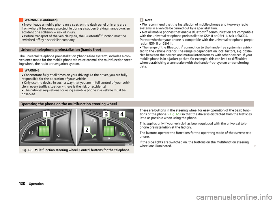
Operating the phone on the multifunction steering wheel
Fig. 128
Multifunction steering wheel: Control buttons for the telephone
There are buttons in the steering wheel for easy operation of the basic func-
tions of the phone » Fig. 128 so that the driver is distracted from the traffic as
little as possible when using the phone.
This applies only if your vehicle has been equipped with the universal tele-
phone preinstallation at the factory.
The buttons operate the functions for the operating mode of the current tele-
phone.
If the side lights are switched on, the buttons on the multifunction steering
wheel are illuminated. 120Operation
Page 123 of 246
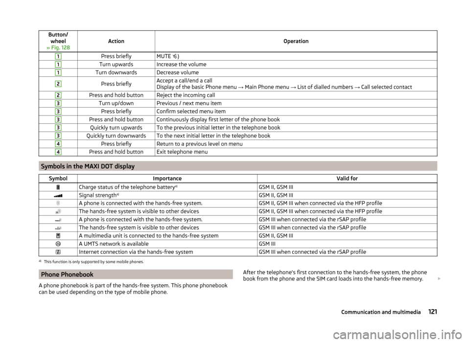
Button/wheel
» Fig. 128ActionOperation
1Press brieflyMUTE )1Turn upwardsIncrease the volume1Turn downwardsDecrease volume2Press brieflyAccept a call/end a call
Display of the basic Phone menu → Main Phone menu → List of dialled numbers → Call selected contact2Press and hold buttonReject the incoming call3Turn up/downPrevious / next menu item3Press brieflyConfirm selected menu item3Press and hold buttonContinuously display first letter of the phone book3Quickly turn upwardsTo the previous initial letter in the telephone book3Quickly turn downwardsTo the next initial letter in the telephone book4Press brieflyReturn to a previous level on menu4Press and hold buttonExit telephone menu
Symbols in the MAXI DOT display
SymbolImportanceValid forCharge status of the telephone battery a)GSM II, GSM IIISignal strengtha)GSM II, GSM IIIA phone is connected with the hands-free system.GSM II, GSM III when connected via the HFP profileThe hands-free system is visible to other devicesGSM II, GSM III when connected via the HFP profileA phone is connected with the hands-free system.GSM III when connected via the rSAP profileThe hands-free system is visible to other devicesGSM III when connected via the rSAP profileA multimedia unit is connected to the hands-free systemGSM II, GSM IIIA UMTS network is availableGSM IIIInternet connection via the hands-free systemGSM III when connected via the rSAP profilea)
This function is only supported by some mobile phones.
Phone Phonebook
A phone phonebook is part of the hands-free system. This phone phonebook
can be used depending on the type of mobile phone.After the telephone's first connection to the hands-free system, the phone
book from the phone and the SIM card loads into the hands-free memory. 121Communication and multimedia
Page 124 of 246
Each time the telephone has established a new connection with the hands-
free system, an update of the relevant phone book is performed. The updating
can take a few minutes. During this period, the available phone book is the one
stored at the previous update. Newly stored telephone numbers are only
shown after the updating has ended.
The update is interrupted if a telephone event (e.g. incoming or outgoing call, voice control dialogue) occurs during the updating procedure. After the tele-
phone event has ended, the updating starts anew.
GSM II
The internal phonebook provides 2 500 free memory locations. Each contact
can contain up to 4 numbers.
On vehicles fitted with the Columbus navigation system, a maximum of 1 200
telephone contacts are shown on the display of this appliance.
If the number of contacts loaded exceeds 2 500, the phone book is not com-
plete.
GSM III
The internal phonebook provides 2 000 free memory locations. Each contact
can contain up to 5 numbers.
On vehicles fitted with the Columbus navigation system, a maximum of 1 000
telephone contacts are shown on the display of this appliance.
If the mobile phone's telephone book has more than 2,000 contacts, the fol- lowing message will appear in the MAXI DOTdisplay:
Phone book not fully loaded
Universal telephone preinstallation GSM II
Introduction
This chapter contains information on the following subjects:
Connecting the mobile phone to the hands-free system
122
Telephone operation in the MAXI DOT display
123The universal telephone preinstallation GSM II comprises the following func-
tions.
› Phone Phonebook
» page 121.
› Convenience operation of the telephone via the multifunction steering
wheel » page 120 .
› Telephone operation in the MAXI DOT display
» page 120.
› Voice control of the telephone
» page 129.
› Music playback from the telephone or other multimedia units
» page 131.
All communication between a mobile phone and your vehicle's hands-free sys-
tem is established with the help of Bluetooth ®
technology.
Note
The following guidelines must be observed » page 119, Mobile phones and
two-way radio systems .
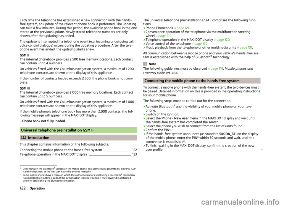
Connecting the mobile phone to the hands-free system
To connect a mobile phone with the hands-free system, the two devices must
be paired. Detailed information on this is provided in the operating instructions
for your mobile phone.
The following steps must be carried out for the connection.
›
Activate Bluetooth ®
and the visibility of your mobile phone on your tele-
phone.
›
Switch on the ignition.
›
Select the Phone - New user menu in the MAXI DOT display and wait until
the hands-free system has completed the search.
›
Select the phone you wish to connect from the list of units found.
›
Confirm the PIN 1)
.
›
If the hands-free system announces (as standard SKODA_BT) on the display
of the mobile phone, enter the PIN 1 )
within 30 seconds and wait, until the
connection is established 2)
.
›
To finish pairing in the MAXI DOT display, confirm the creation of the new
user profile.
1)
Depending on the Bluetooth®
version on the mobile phone, an automatically generated 6-digit PIN (SSP)
is either displayed, or the PIN 1234 has to be entered manually.
2)
Some mobile phones have a menu, in which the authorisation for establishing a Bluetooth ®
connection
is completed by inputting a code. If the authorisation input is required, it must always be performed
when re-establishing the Bluetooth connection.
122Operation