start stop button SKODA SUPERB 2014 2.G / (B6/3T) Owner's Manual
[x] Cancel search | Manufacturer: SKODA, Model Year: 2014, Model line: SUPERB, Model: SKODA SUPERB 2014 2.G / (B6/3T)Pages: 246, PDF Size: 17.16 MB
Page 29 of 246
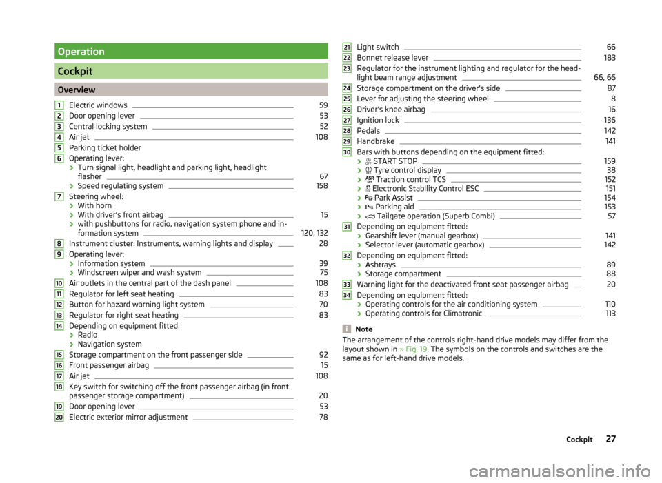
Operation
Cockpit
OverviewElectric windows
59
Door opening lever
53
Central locking system
52
Air jet
108
Parking ticket holder
Operating lever: › Turn signal light, headlight and parking light, headlight
flasher
67
› Speed regulating system
158
Steering wheel:
› With horn
› With driver’s front airbag
15
›with pushbuttons for radio, navigation system phone and in-
formation system
120, 132
Instrument cluster: Instruments, warning lights and display
28
Operating lever:
› Information system
39
›Windscreen wiper and wash system
75
Air outlets in the central part of the dash panel
108
Regulator for left seat heating
83
Button for hazard warning light system
70
Regulator for right seat heating
83
Depending on equipment fitted:
› Radio
› Navigation system
Storage compartment on the front passenger side
92
Front passenger airbag
15
Air jet
108
Key switch for switching off the front passenger airbag (in front
passenger storage compartment)
20
Door opening lever
53
Electric exterior mirror adjustment
781234567891011121314151617181920Light switch66
Bonnet release lever
183
Regulator for the instrument lighting and regulator for the head-
light beam range adjustment
66, 66
Storage compartment on the driver's side
87
Lever for adjusting the steering wheel
8
Driver’s knee airbag
16
Ignition lock
136
Pedals
142
Handbrake
141
Bars with buttons depending on the equipment fitted:
›
START STOP
159
›
Tyre control display
38
›
Traction control TCS
152
›
Electronic Stability Control ESC
151
›
Park Assist
154
›
Parking aid
153
›
Tailgate operation (Superb Combi)
57
Depending on equipment fitted:
› Gearshift lever (manual gearbox)
141
›Selector lever (automatic gearbox)
142
Depending on equipment fitted:
› Ashtrays
89
›Storage compartment
88
Warning light for the deactivated front seat passenger airbag
20
Depending on equipment fitted:
› Operating controls for the air conditioning system
110
›
Operating controls for Climatronic
113
Note
The arrangement of the controls right-hand drive models may differ from the
layout shown in » Fig. 19. The symbols on the controls and switches are the
same as for left-hand drive models.212223242526272829303132333427Cockpit
Page 57 of 246
The tow-away protection triggers the alarm if a vehicle is registered as being
on an inclination.
Activating
The interior monitor and the towing protection are activated automatically af-
ter the vehicle is locked.
Deactivating›
Switch off the ignition.
›
Open the driver door.
›
Press
» Fig. 36 on the B-column on the driver's side. The symbol lighting in
the button changes
from red to orange.
›
Lock the vehicle within 30 seconds.
Deactivate the interior monitor and the towing protection if there is a possibili-
ty of the alarm being triggered by movements (e.g. by children or animals)
within the vehicle interior or if the vehicle has to be transported (e.g. by train
or ship) or towed.
CAUTION
■ The opened glasses storage compartment reduces the effectiveness of the
interior monitor. To ensure the full functionality of the interior monitor, the
glasses storage compartment must always be closed before locking the vehi-
cle.■
The anti-theft alarm system is activated when the vehicle is locked even if
the safe securing system is deactivated. The interior monitor is however not
activated.
Luggage compartment lid
Introduction
This chapter contains information on the following subjects:
Twindoor - open/close small boot lid
55
TwinDoor - open / close large boot
56
Open / close (Superb Combi)
56
Delayed locking of the boot lid
56WARNING■ Ensure that the lock is properly engaged after closing the boot lid. Other-
wise, the lid might open suddenly while the vehicle is moving, even if the
lid was locked – risk of accident!■
Never drive with the boot lid open or ajar, as otherwise exhaust gases
may get into the interior of the vehicle – risk of poisoning!
■
Do not press on the rear window when closing the luggage compartment
lid, as otherwise this could crack – risk of injury!
CAUTION
If the vehicle was locked before the boot lid was closed, the lid is immediately
locked automatically when closed » page 56.
Note
■
The function of the button in the grip above the licence plate is deactivated
when starting off or at a speed of 5 km/hour or more for vehicles with central
locking. The function is restored after the vehicle stops and the door is
opened.■
Repeated opening and closing of the boot lid can lead to a temporary failure
of the function due to the overheating protection of the motors of the Twin-
door system.
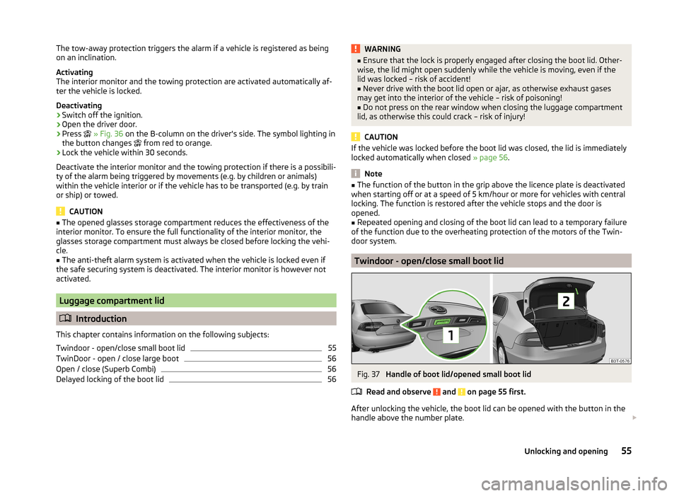
Twindoor - open/close small boot lid
Fig. 37
Handle of boot lid/opened small boot lid
Read and observe
and on page 55 first.
After unlocking the vehicle, the boot lid can be opened with the button in the
handle above the number plate.
55Unlocking and opening
Page 114 of 246
adjustingRead and observe
on page 110 first.
Recommended basic settings of the control elements of the air conditioning system for the respective operating modes:
SettingsControl dial settings » Fig. 124 on page 110Button » Fig. 124 on page 110Air outlet vents 2 » Fig. 122
on page 108ABCDefrost/defog windscreen and
side windows a)Desired tempera-
ture3 or 4Automaticallyswitched onDo not switch onOpen and align with the side windowThe fastest heatingTo the right up tothe stop3Switched offBriefly switch onOpeningComfortable heatingDesired tempera- ture2 or 3Switched offDo not switch onOpeningThe fastest coolingTo the left up to
the stopbriefly 4, then 2 or 3ActivatedBriefly switch onOpeningComfortable coolingDesired tempera- ture1, 2 or 3ActivatedDo not switch onOpen and align to the roofFresh air mode - ventilationTo the left up tothe stopDesired positionSwitched offDo not switch onOpeninga)
We recommend that you do not use this setting in countries with high humidity levels. This can result in heavy cooling of the window glass and the following fogging from outside.
We recommend that you leave the air outlet vents 3 » Fig. 122 on page 108 in
the opened position.
Recirculated air mode
Read and observe
on page 110 first.
Recirculated air mode prevents polluted air outside the vehicle from getting in-to the vehicle, for example when driving through a tunnel or when standing in
a traffic jam.
Switching on/off
›
Press the button.
The indicator light in the button lights up.
›
Press the button again.
The indicator light in the button goes out.
Recirculated air mode is switched off automatically if the air distribution con-
trol C » Fig. 124 on page 110 is turned to the position.
Recirculated air mode can be switched on again from this setting by repeatedly pressing the symbol button
.WARNINGDo not leave recirculated air mode on over a longer period of time, as
“stale” air can cause fatigue of the driver and passengers, reduce attention
levels and also cause the windows to mist up. The risk of having an acci-
dent increases. Switch off recirculated air mode as soon as the windows
start to mist up.112Operation
Page 134 of 246
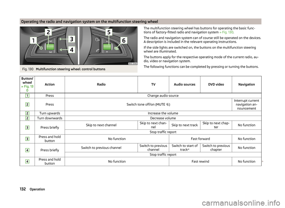
Operating the radio and navigation system on the multifunction steering wheelFig. 130
Multifunction steering wheel: control buttons
The multifunction steering wheel has buttons for operating the basic func-
tions of factory-fitted radio and navigation system » Fig. 130.
The radio and navigation system can of course still be operated on the devices.
A description is included in the relevant operating instructions.
If the side lights are switched on, the buttons on the multifunction steering wheel are illuminated.
The buttons apply for the respective operating mode of the current radio, au-
dio, video or navigation system.
The following functions can be completed by pressing or turning the buttons.Button/ wheel
» Fig. 13 0
ActionRadioTVAudio sourcesDVD videoNavigation
1PressChange audio source2
PressSwitch tone off/on (MUTE
)Interrupt current
navigation an-nouncement2Turn upwardsIncrease the volume2Turn downwardsDecrease volume3
Press brieflySkip to next channelSkip to next chan- nelSkip to next trackSkip to next chap- terNo functionStop traffic report3Press and holdbuttonNo functionFast forwardNo function4
Press brieflySwitch to previous channelSwitch to previous channelSwitch to start of tracka)Switch to previous
chapterNo functionStop traffic report4Press and holdbuttonNo functionFast rewindNo function 132Operation
Page 135 of 246
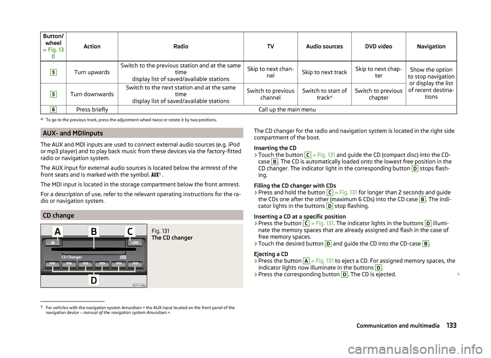
Button/wheel
» Fig. 13 0
ActionRadioTVAudio sourcesDVD videoNavigation
5
Turn upwardsSwitch to the previous station and at the same time
display list of saved/available stationsSkip to next chan- nelSkip to next trackSkip to next chap- terShow the option
to stop navigation or display the list
of recent destina- tions5
Turn downwardsSwitch to the next station and at the same time
display list of saved/available stationsSwitch to previous channelSwitch to start of tracka)Switch to previous
chapter6Press brieflyCall up the main menua)
To go to the previous track, press the adjustment wheel twice or rotate it by two positions.
AUX- and MDIinputs
The AUX and MDI inputs are used to connect external audio sources (e.g. iPod
or mp3 player) and to play back music from these devices via the factory-fitted
radio or navigation system.
The AUX input for external audio sources is located below the armrest of the
front seats and is marked with the symbol. 1)
.
The MDI input is located in the storage compartment below the front armrest.
For a description of use, refer to the relevant operating instructions for the ra-
dio or navigation system.
CD change
Fig. 131
The CD changer
The CD changer for the radio and navigation system is located in the right side
compartment of the boot.
Inserting the CD›
Touch the button
C
» Fig. 131 and guide the CD (compact disc) into the CD-
case
B
. The CD is automatically loaded onto the lowest free position in the
CD changer. The indicator light in the corresponding button
D
stops flash-
ing.
Filling the CD changer with CDs
›
Press and hold the button
C
» Fig. 131 for longer than 2 seconds and guide
the CDs one after the other (maximum 6 CDs) into the CD case
B
. The indi-
cator lights in the buttons
D
stop flashing.
Inserting a CD at a specific position
›
Press the button
C
» Fig. 131 . The indicator lights in the buttons
D
illumi-
nate the memory spaces that are already assigned and flash in the case of
free memory spaces.
›
Touch the desired button
D
and guide the CD into the CD-case
B
.
Ejecting a CD
›
Press the button
A
» Fig. 131 to eject a CD. For assigned memory spaces, the
indicator lights now illuminate in the buttons
D
.
›
Press the corresponding button
D
. The CD is ejected.
1)
For vehicles with the navigation system Amundsen + the AUX input located on the front panel of the
navigation device » manual of the navigation system Amundsen + .
133Communication and multimedia
Page 140 of 246
CAUTION■Avoid high engine revolutions, full throttle and high engine loads before the
engine has reached its operating temperature – risk of damaging the engine!■
Do not switch the engine off immediately at the end of your journey after the
engine has been operated over a prolonged period at high loads but leave it to
run at an idling speed for about 1 minute. This prevents any possible accumula-
tion of heat when the engine is switched off.
For the sake of the environment
Do not warm up the engine while the vehicle is stationary. If possible, start
your journey as soon as the engine has started. Through this the engine rea-
ches its operating temperature more rapidly and the pollutant emissions are
lower.
Note
■ The system is protected against inadvertently switching off the engine while
driving, this means that the engine can only be switched off in an emergen-
cy » page 140 .■
After switching off the ignition, the radiator fan may intermittently continue
to operate for approx. 10 minutes.
■
Under certain circumstances (e.g. after switching off the ignition and opening
the driver's door), the steering is enabled only when the ignition is switched on
or the engine is started.
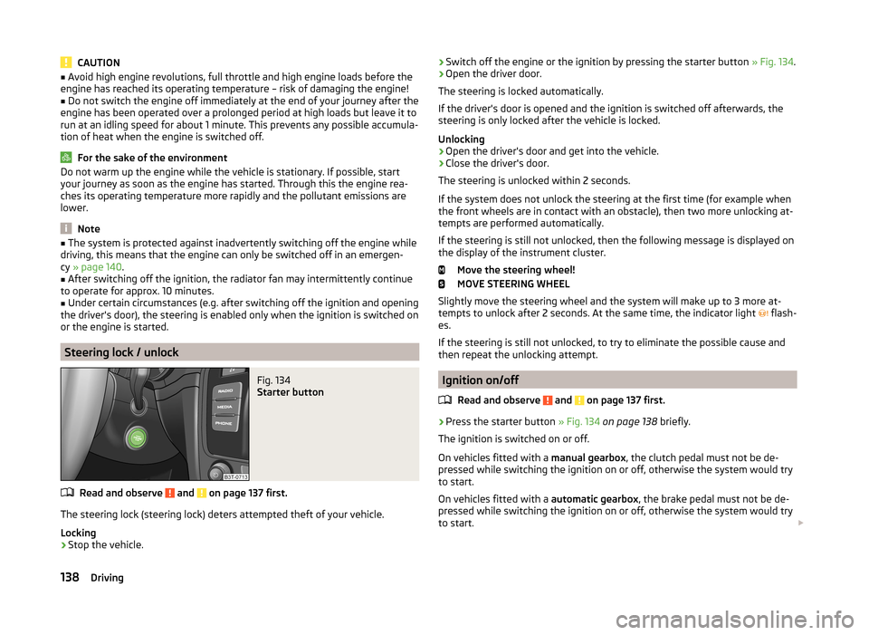
Steering lock / unlock
Fig. 134
Starter button
Read and observe and on page 137 first.
The steering lock (steering lock) deters attempted theft of your vehicle.
Locking
›
Stop the vehicle.
› Switch off the engine or the ignition by pressing the starter button
» Fig. 134.›Open the driver door.
The steering is locked automatically.
If the driver's door is opened and the ignition is switched off afterwards, the
steering is only locked after the vehicle is locked.
Unlocking›
Open the driver's door and get into the vehicle.
›
Close the driver's door.
The steering is unlocked within 2 seconds.
If the system does not unlock the steering at the first time (for example when
the front wheels are in contact with an obstacle), then two more unlocking at-
tempts are performed automatically.
If the steering is still not unlocked, then the following message is displayed on the display of the instrument cluster.
Move the steering wheel!
MOVE STEERING WHEEL
Slightly move the steering wheel and the system will make up to 3 more at-
tempts to unlock after 2 seconds. At the same time, the indicator light flash-
es.
If the steering is still not unlocked, to try to eliminate the possible cause and
then repeat the unlocking attempt.
Ignition on/off
Read and observe
and on page 137 first.
›
Press the starter button » Fig. 134 on page 138 briefly.
The ignition is switched on or off.
On vehicles fitted with a manual gearbox, the clutch pedal must not be de-
pressed while switching the ignition on or off, otherwise the system would try
to start.
On vehicles fitted with a automatic gearbox, the brake pedal must not be de-
pressed while switching the ignition on or off, otherwise the system would try
to start.
138Driving
Page 141 of 246
If the driver's door is opened while the igition is on, an audible signal sounds
and the following message appears in the instrument cluster display.
Ignition on!
IGNITION ON
When leaving the vehicle always switch off the ignition.
Note
The ignition is switched on when indicated by the lighting up of certain indica-
tor lamps in the instrument cluster.
Starting the engine
Read and observe
and on page 137 first.
Vehicles with a diesel engine are equipped with a glow plug system. The glow
plug warning light lights up after the ignition has been switched on. Start
the engine once the warning light has gone out.
You should not switch on any major electrical components during the heating
period otherwise the vehicle battery will be drained unnecessarily.
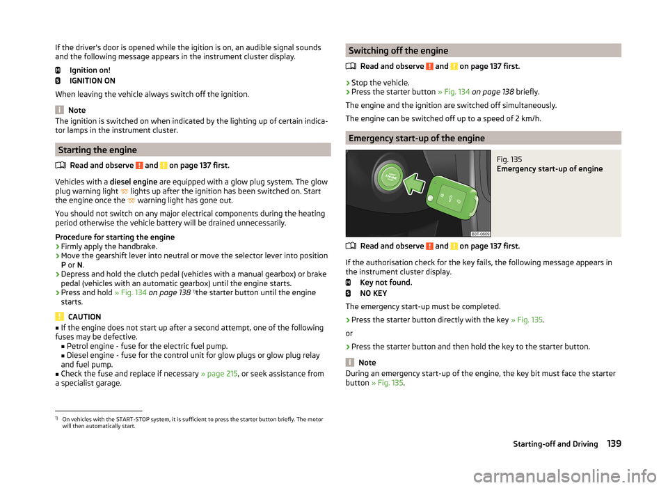
Procedure for starting the engine
›
Firmly apply the handbrake.
›
Move the gearshift lever into neutral or move the selector lever into position
P or N.
›
Depress and hold the clutch pedal (vehicles with a manual gearbox) or brake
pedal (vehicles with an automatic gearbox) until the engine starts.
›
Press and hold » Fig. 134 on page 138 1)
the starter button until the engine
starts.
CAUTION
■ If the engine does not start up after a second attempt, one of the following
fuses may be defective. ■ Petrol engine - fuse for the electric fuel pump.
■ Diesel engine - fuse for the control unit for glow plugs or glow plug relay
and fuel pump.■
Check the fuse and replace if necessary » page 215, or seek assistance from
a specialist garage.
Switching off the engine
Read and observe
and on page 137 first.
›
Stop the vehicle.
›
Press the starter button » Fig. 134 on page 138 briefly.
The engine and the ignition are switched off simultaneously.
The engine can be switched off up to a speed of 2 km/h.
Emergency start-up of the engine
Fig. 135
Emergency start-up of engine
Read and observe and on page 137 first.
If the authorisation check for the key fails, the following message appears in
the instrument cluster display.
Key not found.
NO KEY
The emergency start-up must be completed.
› Press the starter button directly with the key
» Fig. 135.
or
› Press the starter button and then hold the key to the starter button.
Note
During an emergency start-up of the engine, the key bit must face the starter
button » Fig. 135 .1)
On vehicles with the START-STOP system, it is sufficient to press the starter button briefly. The motor
will then automatically start.
139Starting-off and Driving
Page 142 of 246
Emergency ignition shutoff systemRead and observe
and on page 137 first.
The ignition can be turned off in an emergency even when travelling at a
speed of more than 2 km / hr.
›
Press the starter button » Fig. 134 on page 138 for longer than 1 second or
twice within 1 second.
After emergency stop of the ignition, the steering is unlocked.
Brakes
Introduction
This chapter contains information on the following subjects:
Information on braking
140
Handbrake
141WARNING■ Greater physical effort is required for braking when the engine is switch-
ed off – risk of accident!■
The clutch pedal must be actuated when braking on a vehicle with man-
ual transmission, when the vehicle is in gear and at low revs. Otherwise,
the function of the brake booster may be impaired – risk of accident!
■
When leaving the vehicle, never leave persons who might, for example,
release the handbrake or take the vehicle out of gear unattended in the ve-
hicle. The vehicle could then start to move – risk of accident!
WARNINGIn the case of damage to the standard fitted front spoiler or if retrofitting
another front spoiler, hub caps etc. » page 169, Services, modifications,
and technical alterations , make sure that the air supply to the front brakes
is not affected. The front brakes may overheat, which can have a negative
impact on the functioning of the braking system – risk of accident!
CAUTION
■ Observe the recommendations on the new brake pads » page 145.■Never let the brakes slip with light pressure on the pedal if braking is not
necessary. This causes the brakes to overheat and can also result in a longer
braking distance and excessive wear.Information on braking
Read and observe
and on page 140 first.
If the brakes are applied in full and the control unit for the braking system con-siders the situation to be dangerous for the following traffic, the brake light
flashes automatically.
After the speed was reduced below around 10 km/h or the vehicle was stop-
ped, the brake light stops flashing and the hazard warning light system
switches on. The hazard warning light system is switched off automatically af- ter accelerating or driving off again.
Before travelling a long distance with a steep gradient, reduce speed and shift
into the next lowest gear. As a result, the braking effect of the engine will be
used, reducing the load on the brakes. Any additional braking should be com-
pleted intermittently, not continuously.
Wear-and-tear
The wear of the brake pads is dependent on the operating conditions and driv-
ing style.
The brake pads wear more quickly if a lot of journeys are completed in towns
and over short distances or if a very sporty style of driving is adopted.
Under these severe conditions , the thickness of the brake pads must also be
checked by a specialist garage between service intervals.
Wet roads or road salt
The performance of the brakes can be delayed as the brake discs and brake
pads may be moist or have a coating of ice or layer of salt on them in winter.
The brakes are cleaned and dried by applying the brakes several times.
Corrosion
Corrosion on the brake discs and dirt on the bake pads occur if the vehicle has been parked for a long period and if you do not make much use of the braking
system. The brakes are cleaned and dried by applying the brakes several times.
Faults in the brake surface
If it is found that the braking distance has suddenly become longer and that
the brake pedal can be depressed further, the brake system may be faulty.
Visit a specialist garage immediately and adjust your style of driving appropri-
ately, as you will not know the exact extent of the damage.
140Driving
Page 144 of 246
WARNINGNever engage reverse gear when driving – risk of accident!
CAUTION
If not in the process of changing gear, do not leave your hand on the gearshift
lever while driving. The pressure from the hand can cause the gearshift mech-
anism to wear excessively.
Pedals
The operation of the pedals must not be hindered under any circumstances!
In the driver's footwell, only a footmat, which is attached to the two corre-
sponding attachment points, may be used.
Only use factory-supplied footmats or footmats from the range of ŠKODAOrigi-
nal Accessories, which are fitted to two attachment points.
WARNINGNo objects may be placed in the driver's footwell – risk due to obstruction
or limitation of pedal operation.
Automatic gearbox
Introduction
This chapter contains information on the following subjects:
Modes and use of selector lever
142
Manual shifting of gears (Tiptronic)
143
Starting-off and driving
144
Malfunction
144WARNING■ Do not depress the accelerator if changing the forward driving mode –
risk of accident!■
Never move the selector lever to mode R or P when driving – risk of acci-
dent!
■
When the vehicle is stationery and the engine is running, the vehicle must
be held in mode D, S or R with the brake pedal. Even when the engine is
idling, the power transmission is never completely interrupted – the vehicle
creeps.
CAUTION■ If the selector lever is moved to mode N while driving, the accelerator pedal
must be released and you will need to wait until the engine has reached its
idling speed before moving the selector lever to a forward driving mode again.■
At temperatures below -10 °C, the engine can only be started in the selector
lever position P.
■
When stopping on a slope, never try to hold the vehicle using the accelerator
pedal – this may lead to gear damage.
Note
After the ignition is switched off, the ignition key can only be withdrawn if the
selector lever is in the position P.
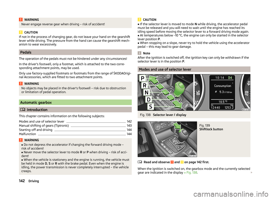
Modes and use of selector lever
Fig. 138
Selector lever / display
Fig. 139
Shiftlock button
Read and observe and on page 142 first.
When the ignition is switched on, the gearbox mode and the currently selected
gear are indicated in the display » Fig. 138.
142Driving
Page 145 of 246
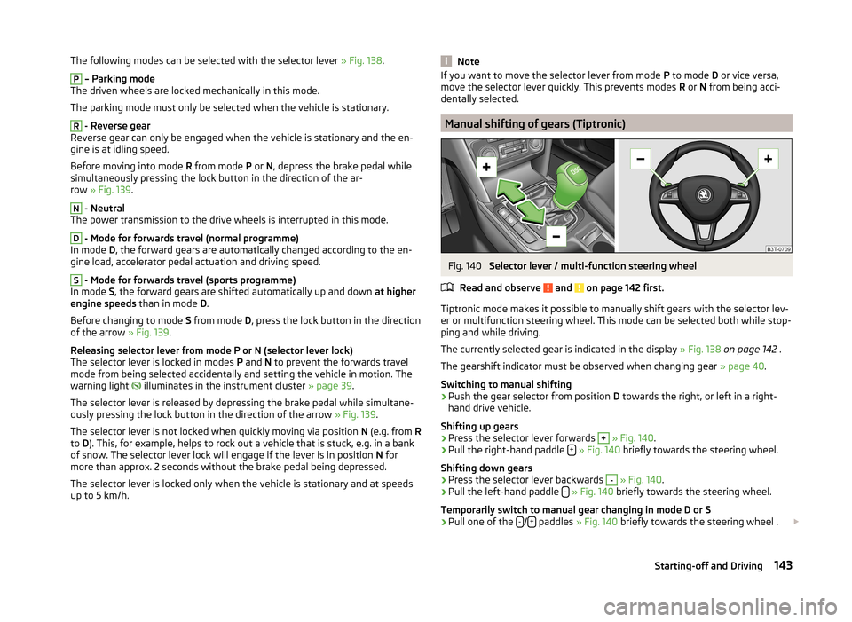
The following modes can be selected with the selector lever » Fig. 138.P
– Parking mode
The driven wheels are locked mechanically in this mode.
The parking mode must only be selected when the vehicle is stationary.
R
- Reverse gear
Reverse gear can only be engaged when the vehicle is stationary and the en-
gine is at idling speed.
Before moving into mode R from mode P or N, depress the brake pedal while
simultaneously pressing the lock button in the direction of the ar-
row » Fig. 139 .
N
- Neutral
The power transmission to the drive wheels is interrupted in this mode.
D
- Mode for forwards travel (normal programme)
In mode D, the forward gears are automatically changed according to the en-
gine load, accelerator pedal actuation and driving speed.
S
- Mode for forwards travel (sports programme)
In mode S, the forward gears are shifted automatically up and down at higher
engine speeds than in mode D.
Before changing to mode S from mode D, press the lock button in the direction
of the arrow » Fig. 139.
Releasing selector lever from mode P or N (selector lever lock)
The selector lever is locked in modes P and N to prevent the forwards travel
mode from being selected accidentally and setting the vehicle in motion. The
warning light illuminates in the instrument cluster
» page 39.
The selector lever is released by depressing the brake pedal while simultane-
ously pressing the lock button in the direction of the arrow » Fig. 139.
The selector lever is not locked when quickly moving via position N (e.g. from R
to D). This, for example, helps to rock out a vehicle that is stuck, e.g. in a bank
of snow. The selector lever lock will engage if the lever is in position N for
more than approx. 2 seconds without the brake pedal being depressed.
The selector lever is locked only when the vehicle is stationary and at speeds up to 5 km/h.
NoteIf you want to move the selector lever from mode P to mode D or vice versa,
move the selector lever quickly. This prevents modes R or N from being acci-
dentally selected.
Manual shifting of gears (Tiptronic)
Fig. 140
Selector lever / multi-function steering wheel
Read and observe
and on page 142 first.
Tiptronic mode makes it possible to manually shift gears with the selector lev-
er or multifunction steering wheel. This mode can be selected both while stop-
ping and while driving.
The currently selected gear is indicated in the display » Fig. 138 on page 142 .
The gearshift indicator must be observed when changing gear » page 40.
Switching to manual shifting
›
Push the gear selector from position D towards the right, or left in a right-
hand drive vehicle.
Shifting up gears
›
Press the selector lever forwards
+
» Fig. 140 .
›
Pull the right-hand paddle +
» Fig. 140 briefly towards the steering wheel.
Shifting down gears
›
Press the selector lever backwards
-
» Fig. 140 .
›
Pull the left-hand paddle -
» Fig. 140 briefly towards the steering wheel.
Temporarily switch to manual gear changing in mode D or S
›
Pull one of the -/+ paddles
» Fig. 140 briefly towards the steering wheel .
143Starting-off and Driving