boot SKODA SUPERB 2014 2.G / (B6/3T) Service Manual
[x] Cancel search | Manufacturer: SKODA, Model Year: 2014, Model line: SUPERB, Model: SKODA SUPERB 2014 2.G / (B6/3T)Pages: 246, PDF Size: 17.16 MB
Page 180 of 246
Artificial leather, cloths and Alcantara®
Read and observe
and on page 176 first.
Artificial leather
Clean artificial leather with a damp cloth.
If this method does not completely clean the artificial leather, use a mild soap
solution or cleaning products specially designed for this purpose.
Fabric
Clean upholstery cover materials and cloth trims on doors, boot cover, etc. us-
ing specific cleaning agents, e.g., dry foam.
Use a soft sponge, brush, or commercially available microfibre cloth.
Use a cloth and special detergent to clean the roof trim.
Remove any lumps on the cover fabric and any fabric residue using a brush.
Remove stubborn hair using a “cleaning glove”.
Alcantara ®
Dust and fine dirt particles in pores, creases and seams may chafe and damage
the surface.
If you leave your vehicle parked in the open for lengthy periods, protect the Al-
cantara ®
seat covers from the direct rays of the sun to prevent fading.
Minor changes in colour caused by use are normal.
CAUTION
■ Do not use any leather cleaners on Alcantara ®
seat covers.■For Alcantara ®
seat covers do not use any solvents, floor wax, shoe cream,
stain remover, or similar agents.■
Avoid leaving the vehicle in bright sunlight for long periods of time in order
to stop the fabric from bleaching. If the vehicle is parked outside for long peri-
ods of time, cover the fabric to protect it from direct sunlight.
■
Some clothing materials, e.g. dark denim, do not have sufficient colour fast-
ness. This can cause damage or clearly visible discolouration to seat covers,
even when used correctly. This applies particularly to light-coloured seat cov-
ers. This does not relate to a fault in the seat cover, but rather to poor colour
fastness of the clothing textiles.
Seat covers
Read and observe
and on page 176 first.
Electrically heated seats
Do not clean the covers by moistening, as this can damage the seat heating
system.
Use a specific cleaning agent such as dry foam or similar to clean the covers.
Seats without seat heating
Thoroughly vacuum the seat covers with a vacuum cleaner before cleaning.
Clean the seat covers with a damp cloth or cleaning products specially de-
signed for this purpose.
Indented points arising on the fabrics by everyday use, can be removed by
brushing against the direction of hair with a damp brush.
Always clean all parts of the covers, so that there are no visible edges. Then
allow the seat to dry completely.
CAUTION
■ Regularly remove dust from the seat covers using a vacuum cleaner.■Electrically heated seats must not be dried after cleaning by switching on the
heater.■
Do not sit on wet seats - risk of seat deformation.
■
Always clean the seats “from seam to seam”.
Seat belts
Read and observe
and on page 176 first.
The belt webbing must always be kept clean.
Wash dirty seat belts with mild soapy water.
Remove coarse dirt with a soft brush.
Dirty belt webbing may impair the correct functioning of the inertia reel.
WARNING■ The seat belts must not be removed for cleaning.■Never clean the seat belts chemically as chemical cleaning products could
destroy the fabric. 178General Maintenance
Page 193 of 246
■Do not place the battery in direct daylight in order to protect the vehicle bat-
tery housing from the effects of ultra-violet light.■
If the vehicle has not been driven for more than 3 to 4 weeks, the battery will
discharge. This is because certain electrical components consume electricity
(e. g. control units) also in idle state. Prevent the battery from discharging by
disconnecting the battery's negative terminal (-) or continuously charging the
battery with a very low charging current.
■
If the vehicle is frequently used for making short trips, the vehicle battery
will not have time to charge up sufficiently and may discharge.
For the sake of the environment
A vehicle battery that has been removed is a special type of hazardous waste.
These must be disposed of in accordance with national legal regulations.
Note
You should replace batteries older than 5 years.
Open cover
Fig. 166
Engine compartment: Polyester cover of the vehicle battery/
plastic cover of the vehicle battery
Read and observe
and on page 190 first.
The battery is located in the engine compartment in a polyester cover
1
» Fig. 166 , in a plastic cover
2
» Fig. 166 or in the left side of the
boot » page 99 .
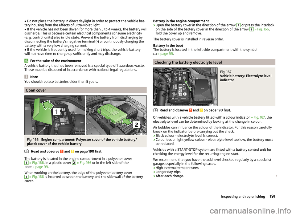
When working on the battery, the edge of the polyester battery cover
1
» Fig. 166 is inserted between the battery and the side wall of the battery
cover.
Battery in the engine compartment›Open the battery cover in the direction of the arrow 1 or press the interlock
on the side of the battery cover in the direction of the arrow 2
» Fig. 166 ,
fold the cover up and remove.
The battery cover is installed in reverse order.
Battery in the boot
The battery is located in the left side compartment with the symbol
» page 99 .
Checking the battery electrolyte level
Fig. 167
Vehicle battery: Electrolyte level
indicator
Read and observe and on page 190 first.
On vehicles with a vehicle battery fitted with a colour indicator » Fig. 167, the
electrolyte level can be determined by looking at the change in colour.
Air bubbles can influence the colour of the indicator. For this reason carefully knock on the indicator before carrying out the check.
› Black colour - electrolyte level is correct.
› Colourless or light yellow colour - electrolyte level too low, the battery must
be replaced.
Vehicles with a START-STOP system are fitted with a battery control unit for
checking the energy level for the recurring engine start.
We recommend that you have the acid level checked regularly by a specialist
garage, especially in the following cases.
› High external temperatures.
› Longer day trips.
› After each charge.
191Inspecting and replenishing
Page 199 of 246
›Switch on the ignition.›Press the
» Fig. 170 symbol button for longer than 2 seconds.
If the warning light
in the instrument cluster lights up and does not go out
after the system configuration, this indicates a system fault.
If the warning light
in the instrument cluster flashes, there is a system fault.
Tyre pressure indicator
The warning light
in the instrument cluster lights up when any of the fol-
lowing conditions are met.
› The tyre inflation pressure is low.
› The structure of the tyre is damaged.
› The vehicle is loaded on one side.
› The wheels of one axle are loaded more heavily (e.g. when towing a trailer or
when driving uphill or downhill).
› Snow chains are mounted.
› The spare wheel is mounted.
› One wheel per axle was changed.WARNING■
When the warning light in the instrument cluster lights up, immediate-
ly reduce the speed and avoid sudden steering and brake manoeuvres.
Stop the vehicle as soon as possible and inspect the tyres and their infla-
tion pressure.■
Under certain circumstances (e.g. sporty style of driving, wintry or un-
paved roads) the warning light
in the instrument cluster can be delayed
or does not light up at all.
CAUTION
■ The system cannot warn in case of very rapid tyre inflation pressure loss, e.g.
in case of sudden tyre damage. In this case carefully bring the vehicle to a
standstill without sudden steering movements or sharp braking.■
To ensure a proper functioning of the tyre control display, it is necessary to
repeat the basic setting every 10000 km or once a year.
■
The tyre pressure monitor does not replace the need to check tyre pressure
regularly.
Spare and temporary spare wheelFig. 171
Fixing the spare or temporary
spare wheel
Read and observe and on page 193 first.
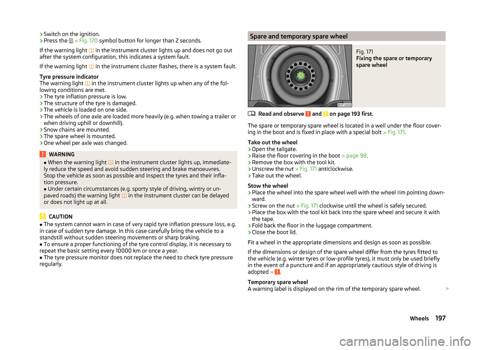
The spare or temporary spare wheel is located in a well under the floor cover-
ing in the boot and is fixed in place with a special bolt » Fig. 171.
Take out the wheel
›
Open the tailgate.
›
Raise the floor covering in the boot » page 98.
›
Remove the box with the tool kit.
›
Unscrew the nut » Fig. 171 anticlockwise.
›
Take out the wheel.
Stow the wheel
›
Place the wheel into the spare wheel well with the wheel rim pointing down-
ward.
›
Screw on the nut » Fig. 171 clockwise until the wheel is safely secured.
›
Place the box with the tool kit back into the spare wheel and secure it with
the tape.
›
Fold back the floor in the luggage compartment.
›
Close the boot lid.
Fit a wheel in the appropriate dimensions and design as soon as possible.
If the dimensions or design of the spare wheel differ from the tyres fitted to
the vehicle (e.g. winter tyres or low-profile tyres), it must only be used briefly
in the event of a puncture and if an appropriately cautious style of driving is
adopted »
.
Temporary spare wheel
A warning label is displayed on the rim of the temporary spare wheel.
197Wheels
Page 202 of 246

Do-it-yourself
Emergency equipment and self-help
Emergency equipment
Introduction
This chapter contains information on the following subjects:
First aid kit and warning triangle
200
fire extinguisher
200
Vehicle tool kit
201
First aid kit and warning triangle
Fig. 173
Stowage compartment for the first aid kit: Superb / Superb Com-
bi
Fig. 174
Placing of the warning triangle
First-aid box
The compartment for stowing the first-aid box is located in the right of the
boot » Fig. 173 .
Warning triangle
The warning triangle can be attached to the rear wall trim panel with rubber
straps » Fig. 174 .WARNINGThe first-aid kit and warning triangle must always be secured safely so that
they do not come loose when making an emergency braking or in a vehicle
collision which could cause injuries to occupants.
Note
■ Pay attention to the expiration date of the first-aid kit.■We recommend using a first-aid kit from ŠKODA Original Accessories, which
are available from a ŠKODA Partner.
fire extinguisher
Fig. 175
Fire extinguisher
The fire extinguisher is attached by two straps in a holder under the driver
seat.
Removing / attaching
›
Loosen the two straps by pulling the buckles in the direction of the ar-
row » Fig. 175 .
›
Remove the fire extinguisher.
Installation is carried out in the reverse order.
Please read carefully the instructions which are attached to the fire extin- guisher.
200Do-it-yourself
Page 203 of 246
The fire extinguisher must be checked by an authorised person once a year.
The national legal requirements must be observed.WARNINGThe fire extinguisher must always be secured safely so that they do not
come loose when making an emergency braking or in a vehicle collision
which could cause injuries to occupants.
Note
■ The fire extinguisher must comply with national legal requirements.■Pay attention to the expiration date of the fire extinguisher. Proper function-
ing of the fire extinguisher is not assured once it has passed its expiry date.■
The fire extinguisher is part of the scope of delivery in certain countries only.
Vehicle tool kit
Fig. 176
Vehicle tool kit
The vehicle tool kit and the lifting jack are housed in a plastic box in the spare
wheel or in the storage space for the spare wheel. There is also space here for
the removable ball rod for the trailer towing device. The box is attached with a
strap on the spare wheel.
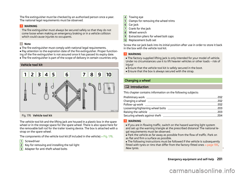
The components of the vehicle tool kit (if included in the vehicle) » Fig. 176.
Screwdriver
Key for removing and installing the tail light
Adapter for anti-theft wheel bolts
123Towing eye
Clamps for removing the wheel trims
Car jack
Crank for the jack
Wheel wrench
Extraction pliers for wheel bolt caps
Replacement bulb set
Screw the car jack back into its initial position after use in order to store it back
in the box with the vehicle tool kit.WARNING■ The factory-supplied lifting jack is only intended for your model of vehicle.
Under no circumstances use it to lift heavier vehicles or other loads – risk of
injury!■
Ensure that the vehicle tool kit is safely secured in the boot.
■
Ensure that the box is always secured with the strap.
Changing a wheel
Introduction
This chapter contains information on the following subjects:
Preliminary work
202
Changing a wheel
202
Follow-up work
202
Loosening/tightening wheel bolts
203
Raising the vehicle
203
Securing wheels against theft
204WARNING■ If you are in flowing traffic, switch on the hazard warning light system
and set up the warning triangle at the prescribed distance! The national le-
gal requirements must be observed.■
Park the vehicle as far away as possible from the flow of traffic. Park on
as flat and firm a surface as possible.
■
The following instructions must be followed if the vehicle is subsequently
fitted with tyres or rims that differ from the factory-fitted ones » page 195,
New tyres .
45678910201Emergency equipment and self-help
Page 204 of 246
WARNINGNotes for vehicle lifting■If the wheel has to be changed on a slope, first of all block the opposite
wheel with a stone or similar object to prevent the vehicle from unexpect-
edly rolling away.■
Secure the base plate of the lifting jack with suitable means to prevent
possible moving. A soft and slippery ground under the base plate may move
the lifting jack, causing the vehicle to fall down. It is therefore always nec-
essary to place the lifting jack on a solid surface or use a wide and stable
base. Use a non-slip base (e.g. a rubber foot mat) if the surface is smooth,
such as cobbled stones, tiled floor, etc.
■
Only attach the lifting jack to the attachment points provided for this pur-
pose.
■
Always raise the vehicle with the doors closed.
■
Never position any body parts, such as arms or legs under the vehicle,
while the vehicle is raised with a lifting jack.
■
Never start the engine when the vehicle is raised – risk of injury.
WARNINGInformation on the wheel bolts■The wheel bolts must be clean and must turn easily. Never treat them
with grease or oil.■
The prescribed tightening torque of the wheel bolts for steel and light al-
loy wheels is 120 Nm.
■
If the wheel bolts are tightened to a too low tightening torque, the rims
could come loose when the car is moving – risk of accident! A tightening
torque which is too high can damage the bolts and threads and this can re-
sult in permanent deformation of the contact surfaces on the rims.
■
In case of incorrect treatment of the wheel bolts, the wheel can loosen
when the car is moving – risk of accident!
Note
The national legal requirements must be observed when changing a wheel.
Preliminary work
Read and observe
on page 201 first.
Always change a wheel on a level surface as far as possible.
The following steps must be carried out before actually changing the wheel:
› Have
all the occupants get out. The passengers should not stand on the
road (instead they should remain behind a crash barrier, for instance) while
the wheel is being changed.›
Switch off the engine.
›
Move the gearshift lever into Neutral or move the selector lever for the auto-
matic gearbox into position P .
›
Apply the handbrake firmly.
›
Uncouple a trailer.
›
Remove the vehicle tool kit » page 201 and the spare wheel » page 197 from
the boot.
Changing a wheel
Read and observe
on page 201 first.
›
Remove the full wheel trim » page 198 or caps » page 198 .
›
First of all slacken the anti-theft wheel bolt and then the other wheel
bolts » page 203 .
›
Jack up the vehicle until the wheel that needs changing is clear of the
ground » page 203 .
›
Unscrew the wheel bolts and place them on a clean surface (cloth, paper,
etc.).
›
Remove the wheel carefully.
›
Attach the spare wheel and slightly screw on the wheel bolts.
›
Lower the vehicle.
›
Alternately tighten wheel bolts opposite (diagonally) with the wheel wrench.
Tighten the anti-theft wheel bolt last » page 203.
›
Replace the wheel trim or the caps.
Note
■
All bolts must be clean and must turn easily.■Under no circumstances grease or oil the wheel bolts!■
When fitting unidirectional tyres, ensure that the direction of rotation is cor-
rect » page 193 .
Follow-up work
Read and observe
on page 201 first.
The following steps must also be performed after changing the wheel.
›
Stow and attach the replaced wheel in the spare wheel well using a special
bolt » page 197 .
202Do-it-yourself
Page 207 of 246

WARNING■A tyre filled with sealant has the same driving characteristics as a stand-
ard tyre.■
Do not travel faster than 80 km/h.
■
Avoid accelerating at full throttle, sharp braking and fast cornering.
■
Check the tyre pressure after driving for 10 minutes.
■
The sealant is hazardous to heath. Remove immediately if it comes into
contact with the skin.
For the sake of the environment
Used sealant or sealant whose expiry date has passed must be disposed of in
accordance with environmental protection regulations.
Note
■ Observe the manufacturer's usage instructions for the breakdown kit.■A new bottle of sealant can be purchased from ŠKODA Original Parts.■
Immediately replace the tyre that was repaired using the breakdown kit, or
consult a specialist garage about repair options.
Breakdown kit
Fig. 181
Principle sketch: Components of the breakdown kit
Read and observe
on page 205 first.
The kit is located in a box under the floor covering in the luggage compart-
ment.
Components of the breakdown kit » Fig. 181
Valve remover
Sticker with speed designation “max. 80 km/h”/“max. 50 mph” Inflation hose with plug
Air compressor
Tyre inflation hose
Tyre inflation pressure indicator
Air release valve
ON and OFF switch
12 volt cable connector
Tyre inflator bottle with sealing agent
Replacement valve core
The valve remover 1
has a slot at its lower end which fits into the valve core.
This is the only way in which you can remove and re-install the valve core from
the tyre valve. The same also applies to the replacement valve core
11
.
Preparations for using the breakdown kit
Read and observe
on page 205 first.
The following preparatory work must be carried out before using the break-
down kit.
›
Park the vehicle as far away as possible from the flow of traffic. Park on as
flat and firm a surface as possible.
›
If you are in flowing traffic, switch on the hazard warning light system and
set up the warning triangle at the prescribed distance! The national legal re-
quirements must be observed.
›
Have all the occupants get out. The passengers should not stand on the
road (instead they should remain behind a crash barrier, for instance) while
the wheel is being changed.
›
Switch off the engine and move the gearshift lever into Neutral or move the
selector lever on the automatic gearbox into position P.
›
Apply the handbrake firmly.
›
Check that you can carry out the repairs with the breakdown kit » page 204.
Uncouple a trailer.
›
Remove the breakdown kit from the boot.
›
Stick the sticker
2
» Fig. 181 on page 205 on the dashboard in the driver's
field of view.
1234567891011205Emergency equipment and self-help
Page 209 of 246
Jump-starting
Introduction
This chapter contains information on the following subjects:
Jump-starting using the battery from another vehicle
207
Jump-starting in vehicles with the START-STOP system
208
Jump-starting vehicles with the vehicle battery in the boot
208WARNING■ A discharged vehicle battery may already freeze at temperatures just be-
low 0 °C. If the battery is frozen, do not jump start with the battery of an-
other vehicle – there is a risk of explosion.■
Pay attention to the warning instructions relating to working in the en-
gine compartment » page 182.
■
The non-insulated parts of the terminal clamps must never touch each
other – there is a risk of short circuit.
■
The jump-start cable connected to the positive terminal of the battery
must not come into contact with electrically conducting parts of the vehicle
– there is a risk of short circuit.
■
Do not clamp the jump-start cable to the negative terminal of the dis-
charged battery. There is the risk of detonating gas seeping out the battery
being ignited by the strong spark which results from the engine being star-
ted.
■
Route the jump-start cables so that they cannot be caught by any rotat-
ing parts in the engine compartment.
■
Do not bend over the battery – there is a risk of caustic burns.
■
The vent screws of the battery cells must be tightened firmly.
■
Keep any sources of ignition (naked flame, smouldering cigarettes, etc.)
away from the battery – risk of explosion!
■
Never jump-start vehicle batteries with insufficient acid levels – risk of
explosion and chemical burns.
CAUTION
■ There must not be any contact between the two vehicles otherwise current
may flow as soon as the negative terminals are connected.■
The discharged battery must be properly connected to the system of the ve-
hicle.
■
We recommend you buy jump-start cables from a car battery specialist.
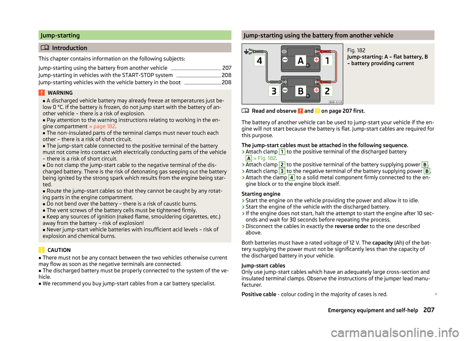
Jump-starting using the battery from another vehicleFig. 182
Jump-starting: A – flat battery, B
– battery providing current
Read and observe and on page 207 first.
The battery of another vehicle can be used to jump-start your vehicle if the en-
gine will not start because the battery is flat. Jump-start cables are required for
this purpose.
The jump-start cables must be attached in the following sequence.
›
Attach clamp
1
to the positive terminal of the discharged battery
A
» Fig. 182 .
›
Attach clamp
2
to the positive terminal of the battery supplying power
B
.
›
Attach clamp
3
to the negative terminal of the battery supplying power
B
.
›
Attach the clamp
4
to a solid metal component firmly connected to the en-
gine block or to the engine block itself.
Starting engine
›
Start the engine on the vehicle providing the power and allow it to idle.
›
Start the engine of the vehicle with the discharged battery.
›
If the engine does not start, halt the attempt to start the engine after 10 sec-
onds and wait for 30 seconds before repeating the process.
›
Disconnect the cables in exactly the reverse order to the one described
above.
Both batteries must have a rated voltage of 12 V. The capacity (Ah) of the bat-
tery supplying the power must not be significantly less than the capacity of
the discharged battery in your vehicle.
Jump-start cables
Only use jump-start cables which have an adequately large cross-section and
insulated terminal clamps. Observe the instructions of the jumper lead manu-
facturer.
Positive cable - colour coding in the majority of cases is red.
207Emergency equipment and self-help
Page 210 of 246
Negative cable - colour coding in the majority of cases is black.
Jump-starting in vehicles with the START-STOP system
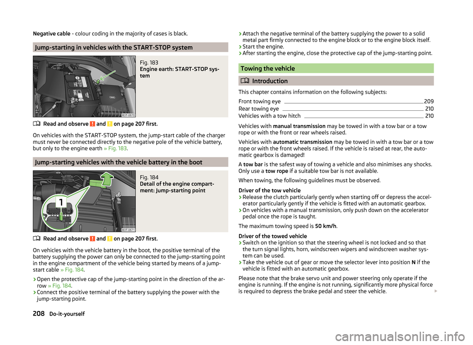
Fig. 183
Engine earth: START-STOP sys-
tem
Read and observe and on page 207 first.
On vehicles with the START-STOP system, the jump-start cable of the charger
must never be connected directly to the negative pole of the vehicle battery,
but only to the engine earth » Fig. 183.
Jump-starting vehicles with the vehicle battery in the boot
Fig. 184
Detail of the engine compart-
ment: Jump-starting point
Read and observe and on page 207 first.
On vehicles with the vehicle battery in the boot, the positive terminal of the
battery supplying the power can only be connected to the jump-starting point
in the engine compartment of the vehicle being started by means of a jump-
start cable » Fig. 184.
›
Open the protective cap of the jump-starting point in the direction of the ar-
row » Fig. 184 .
›
Connect the positive terminal of the battery supplying the power with the
jump-starting point.
› Attach the negative terminal of the battery supplying the power to a solid
metal part firmly connected to the engine block or to the engine block itself.›
Start the engine.
›
After starting the engine, close the protective cap of the jump-starting point.
Towing the vehicle
Introduction
This chapter contains information on the following subjects:
Front towing eye
209
Rear towing eye
210
Vehicles with a tow hitch
210
Vehicles with manual transmission may be towed in with a tow bar or a tow
rope or with the front or rear wheels raised.
Vehicles with automatic transmission may be towed in with a tow bar or a tow
rope or with the front wheels raised. If the vehicle is raised at rear, the auto-
matic gearbox is damaged!
A tow bar is the safest way of towing a vehicle and also minimises any shocks.
Only use a tow rope if a suitable tow bar is not available.
When towing, the following guidelines must be observed.
Driver of the tow vehicle
›
Release the clutch particularly gently when starting off or depress the accel-
erator particularly gently if the vehicle is fitted with an automatic gearbox.
›
On vehicles with a manual transmission, only push down on the accelerator
pedal once the rope is taught.
The maximum towing speed is 50 km/h.
Driver of the towed vehicle
›
Switch on the ignition so that the steering wheel is not locked and so that
the turn signal lights, horn, windscreen wipers and windscreen washer sys-
tem can be used.
›
Take the vehicle out of gear or move the selector lever into position N if the
vehicle is fitted with an automatic gearbox.
Please note that the brake servo unit and power steering only operate if the
engine is running. If the engine is not running, significantly more physical force
is required to depress the brake pedal and steer the vehicle.
208Do-it-yourself
Page 218 of 246
CAUTION■“Never repair” fuses or replace them with a fuse of a higher amperage – risk
of fire! This may also cause damage at another part of the electrical system.■
If a newly inserted fuse blows again after a short time, have the electrical
system checked as quickly as possible by a specialist garage.
■
A blown fuses is recognisable by the molten metal strip. Replace the faulty
fuse with a new one of the same amperage.
Note
■
We recommend always carrying replacement fuses in the vehicle. A box of
replacement fuses can be purchased from ŠKODA Original Accessories.■
There can be several power consuming devices for one fuse.
■
Multiple fuses may exist for a single power consuming device.
Fuses in the dash panel
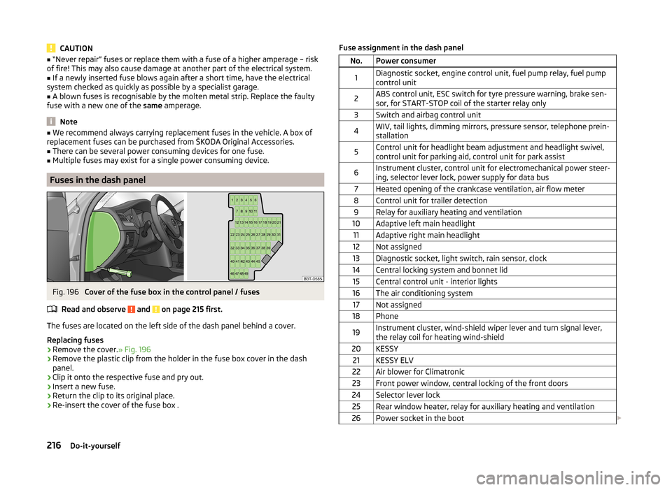
Fig. 196
Cover of the fuse box in the control panel / fuses
Read and observe
and on page 215 first.
The fuses are located on the left side of the dash panel behind a cover.
Replacing fuses
›
Remove the cover. » Fig. 196
›
Remove the plastic clip from the holder in the fuse box cover in the dash
panel.
›
Clip it onto the respective fuse and pry out.
›
Insert a new fuse.
›
Return the clip to its original place.
›
Re-insert the cover of the fuse box .
Fuse assignment in the dash panelNo.Power consumer1Diagnostic socket, engine control unit, fuel pump relay, fuel pump
control unit2ABS control unit, ESC switch for tyre pressure warning, brake sen-
sor, for START-STOP coil of the starter relay only3Switch and airbag control unit4WIV, tail lights, dimming mirrors, pressure sensor, telephone prein-
stallation5Control unit for headlight beam adjustment and headlight swivel,
control unit for parking aid, control unit for park assist6Instrument cluster, control unit for electromechanical power steer-
ing, selector lever lock, power supply for data bus7Heated opening of the crankcase ventilation, air flow meter8Control unit for trailer detection9Relay for auxiliary heating and ventilation10Adaptive left main headlight11Adaptive right main headlight12Not assigned13Diagnostic socket, light switch, rain sensor, clock14Central locking system and bonnet lid15Central control unit - interior lights16The air conditioning system17Not assigned18Phone19Instrument cluster, wind-shield wiper lever and turn signal lever,
the relay coil for heating wind-shield20KESSY21KESSY ELV22Air blower for Climatronic23Front power window, central locking of the front doors24Selector lever lock25Rear window heater, relay for auxiliary heating and ventilation26Power socket in the boot 216Do-it-yourself