engine SKODA SUPERB 2014 2.G / (B6/3T) Workshop Manual
[x] Cancel search | Manufacturer: SKODA, Model Year: 2014, Model line: SUPERB, Model: SKODA SUPERB 2014 2.G / (B6/3T)Pages: 246, PDF Size: 17.16 MB
Page 160 of 246
The system cannot be activated because a fault exists on the vehicle. Seek
help from a specialist garage.
Park Assist stopped. System currently unavailable.
The parking procedure was ended because a fault exists on the vehicle. Seek
help from a specialist garage.
Park Assist faulty. Workshop!
The parking procedure is not possible because a fault exists in the system.
Seek help from a specialist garage.
ASR intervention. take over steering!
The parking procedure is terminated by a TCS intervention. PARK ASSIST Turn on turn signal and select reverse gear
The prerequisites for manoeuvring out of a parking space using the system
have been met. Switch on the turn signals and shift into reverse.
Automatic space departure not possible. Space too small.
The manoeuvring procedure using the system is not possible. The parking gap
is too small.
Park Assist: Brake interv. Speed too high.
The speed was too high during the parking and was automatically reduced.
Cruise Control System
Introduction
This chapter contains information on the following subjects:
Activating/deactivating
158
Storing and maintaining speed
159
Changing the stored speed
159
Switching off temporarily
159
The Cruise Control System (CCS) maintains a set speed, more than 25 km/h,
without you having to actuate the accelerator pedal.
This is only possible within the range which is permitted by the power output and braking power of the engine.
The warning light illuminates in the instrument cluster when the cruise con-
trol system is switched on.
WARNING■ For safety reasons, the cruise control system must not be used in dense
traffic or on unfavourable road surfaces (such as icy roads, slippery roads,
loose gravel) – risk of accident!■
The saved speed may only be resumed if it is not too high for the current
traffic conditions.
■
Always deactivate the cruise control system after use to prevent the sys-
tem being switched on unintentionally.
CAUTION
■ The cruise control system is not able to maintain a constant speed when
driving in areas with steeper gradients. The weight of the vehicle increases the
speed at which it travels. In such cases, select a lower gear or brake the vehi-
cle using the footbrake.■
The cruise control system cannot be activated when first gear or reverse
gear is selected (vehicles with manual transmission).
■
The cruise control system cannot be activated when the selector lever is in
positions P, N or R (vehicles with automatic transmission).
■
The cruise control system may automatically switch off when some brake as-
sist systems (e.g. ESC) intervene, when the maximum permissible engine
speed is exceeded, etc.
Activating/deactivating
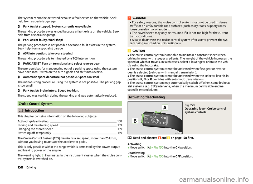
Fig. 150
Operating lever: Cruise control
system controls
Read and observe and on page 158 first.
Activating
›
Move switch
A
» Fig. 150 into the ON position.
Deactivating
›
Move switch
A
» Fig. 150 into the OFF position.
158Driving
Page 161 of 246
Storing and maintaining speedRead and observe
and on page 158 first.
›
Activate the cruise control system » page 158.
›
Drive at the desired speed.
›
Push the rocker button
B
into the SET/- » Fig. 150 on page 158 position.
After you have released the rocker button
B
from the SET/- position, the
speed you have just stored is kept constant without having to depress the ac-
celerator.
Changing the stored speed
Read and observe
and on page 158 first.
Increasing the speed with the rocker button
B›
Push the rocker button
B
into the RES/+ » Fig. 150 on page 158 position.
If the rocker button is held in the RES/+ position, the speed will increase con-
tinuously. Release the rocker button once the desired speed is reached. The
set speed is then stored in the memory.
Decreasing the speed using the rocker button
B
The stored speed can be reduced by pushing the rocker switch
B
into the
SET/- » Fig. 150 on page 158 position.
If the rocker button is pressed and held in the SET/- position, the speed will
decrease continuously. Release the rocker button once the desired speed is
reached. The set speed is then stored in the memory.
If the rocker button is released at a speed of less than approx. 25 km/h, the
speed is not stored and the memory is erased. Once the speed of the vehicle
has increased to more than approx. 25 km/h, the speed must then be stored
again by pushing the rocker button
B
into the SET/- position.
Increasing the speed with the accelerator
›
Depress the accelerator pedal.
Releasing the accelerator pedal will cause the speed to drop again to the set
speed.
Decreasing the speed with the brake pedal
The speed can also be reduced by depressing the brake pedal, which tempora-
rily deactivates the system » page 159.
Switching off temporarily
Read and observe
and on page 158 first.
The cruise control system can be temporarily deactivated by pushing the
switch
A
» Fig. 150 on page 158 into the spring-mounted CANCEL position or
by depressing the brake or clutch pedal.
The set speed remains stored in the memory.
Briefly push the rocker button
B
into the RES/+ position in order to resume
the stored speed after the clutch or brake pedal is released.
START-STOP
Introduction
This chapter contains information on the following subjects:
Operating conditions of the system
160
Operation in vehicles with manual gearbox
160
Operation in vehicles with automatic gearbox
160
System related automatic start-up
161
Manually deactivating/activating the system
161
Information messages
161
The START-STOP system (hereinafter referred to as the system) saves fuel and
reduces polluting emissions and CO 2 emissions by turning the engine off, e.g.
when stopping at traffic lights, and starting the engine again when moving off.
WARNING■ Never let the vehicle roll with the engine switched off.■The brake servo unit and power steering only operate if the engine is run-
ning.159Assist systems
Page 162 of 246
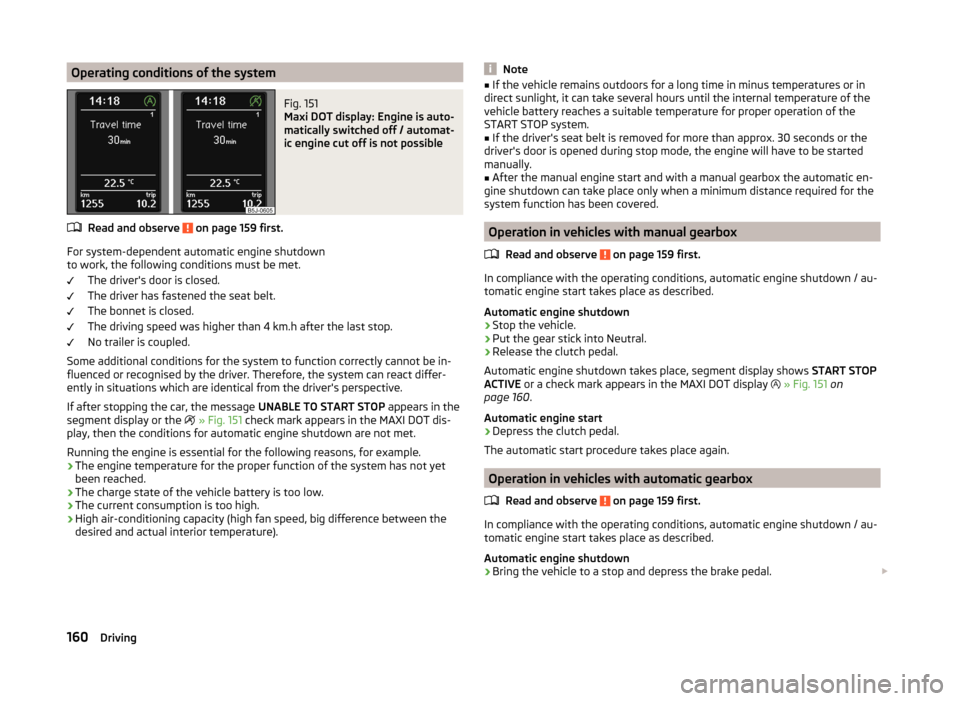
Operating conditions of the systemFig. 151
Maxi DOT display: Engine is auto-
matically switched off / automat-
ic engine cut off is not possible
Read and observe on page 159 first.
For system-dependent automatic engine shutdown
to work, the following conditions must be met.
The driver's door is closed.
The driver has fastened the seat belt.
The bonnet is closed.
The driving speed was higher than 4 km.h after the last stop.
No trailer is coupled.
Some additional conditions for the system to function correctly cannot be in-
fluenced or recognised by the driver. Therefore, the system can react differ-
ently in situations which are identical from the driver's perspective.
If after stopping the car, the message UNABLE TO START STOP appears in the
segment display or the
» Fig. 151 check mark appears in the MAXI DOT dis-
play, then the conditions for automatic engine shutdown are not met.
Running the engine is essential for the following reasons, for example.
› The engine temperature for the proper function of the system has not yet
been reached.
› The charge state of the vehicle battery is too low.
› The current consumption is too high.
› High air-conditioning capacity (high fan speed, big difference between the
desired and actual interior temperature).
Note■ If the vehicle remains outdoors for a long time in minus temperatures or in
direct sunlight, it can take several hours until the internal temperature of the
vehicle battery reaches a suitable temperature for proper operation of the
START STOP system.■
If the driver's seat belt is removed for more than approx. 30 seconds or the
driver's door is opened during stop mode, the engine will have to be started
manually.
■
After the manual engine start and with a manual gearbox the automatic en-
gine shutdown can take place only when a minimum distance required for the
system function has been covered.
Operation in vehicles with manual gearbox
Read and observe
on page 159 first.
In compliance with the operating conditions, automatic engine shutdown / au-
tomatic engine start takes place as described.
Automatic engine shutdown
›
Stop the vehicle.
›
Put the gear stick into Neutral.
›
Release the clutch pedal.
Automatic engine shutdown takes place, segment display shows START STOP
ACTIVE or a check mark appears in the MAXI DOT display
» Fig. 151 on
page 160 .
Automatic engine start
›
Depress the clutch pedal.
The automatic start procedure takes place again.
Operation in vehicles with automatic gearbox
Read and observe
on page 159 first.
In compliance with the operating conditions, automatic engine shutdown / au-
tomatic engine start takes place as described.
Automatic engine shutdown
›
Bring the vehicle to a stop and depress the brake pedal.
160Driving
Page 163 of 246
Automatic engine shutdown takes place, segment display shows START STOP
ACTIVE or a check mark appears in the MAXI DOT display » Fig. 151 on
page 160 .
Automatic engine start›
Release the brake pedal.
The automatic start procedure takes place again.
Further information on automatic transmission
The automatic engine shut down takes place when the selector lever is in po-
sitions P, D , S and N and in Tiptronic mode.
When the selector lever is in position P, the engine remains shut down even
after you release the brake pedal. The engine starts automatically by pressing
the gas pedal or by moving the selector lever into a different mode and releas-
ing the brake pedal.
If the engine is off due to the automatic and the selector lever is put to the R
position then the automatic starts the engine.
If the gear selector is moved from position R to the position D, S or N, the vehi-
cle must reach a speed of more than 10 km / h before the automatic engine
shutdown starts.
There is no automatic engine shutdown when the system detects a vehicle
moving due to a large steering angle.
No automatic engine shutdown takes place when the vehicle is moving at low
speed (e.g. during a traffic jam or when tuning) and remains stationary after
pressing the brake pedal lightly. Automatic engine shutdown takes place if you
press the brake pedal down with more force.
System related automatic start-up
Read and observe
on page 159 first.
When the engine is off, the system can automatically start the engine before
the desired journey continues. Some possible reasons for this are:
› The vehicle begins to roll, e.g. on a slope.
› The brake pedal has been actuated several times.
› The current consumption is too high.
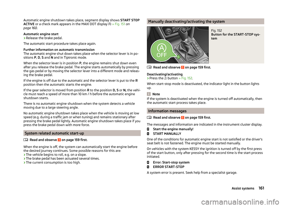
Manually deactivating/activating the systemFig. 152
Button for the START-STOP sys-
tem
Read and observe on page 159 first.
Deactivating/activating
›
Press the button
» Fig. 152 .
When start-stop mode is deactivated, the indicator light in the button lights
up.
Note
If the system is deactivated when the engine is turned off automatically, then
the automatic start process takes place.
Information messages
Read and observe
on page 159 first.
The messages and information are indicated in the instrument cluster display. Start the engine manually!
START MANUALLY
One of the conditions for automatic engine start is not satisfied or the driver's
seat belt is not fastened. The engine must be started manually.
On vehicles with the system KESSY the ignition is turned off by the first press
of the start button, only after pressing for the second time is the start process
initiated.
Error: Start-stop system
ERROR START-STOP
A system error is present. Seek help from a specialist garage.
161Assist systems
Page 168 of 246
CAUTION■If the lever is held firm and not pushed downwards as far as it can go, it will
go back up after the ball head is removed and will not latch into the ready po-
sition. The tow bar will then need to be brought into this position before the
next time it is fitted.■
Stow the ball head in the ready position with the key inserted in the box.
When doing so, make the side opposite to the inserted key face downwards –
there is a risk of damaging the key.
■
Do not use excessive force when handling the operating lever (e.g. do not
step on it).
Note
■ We recommend putting the protective cover onto the ball head before re-
moving the tow bar.■
Clean any dirt from the tow bar before stowing it away in the box with the
vehicle tool kit.
Use and care
Read and observe
and on page 163 first.
Close the mounting recess with the cover to prevent any dirt from getting in.
Always check the tow bar before hitching a trailer. Apply suitable grease
where necessary.
Use the protective cover when stowing away the tow bar, in order to stop the
boot from getting dirty.
In the event of dirt, clean the surfaces of the mounting recess and treat with a
suitable preservative.
CAUTION
Apply grease to the upper part of the mounting recess. Make sure you do not
remove any grease.
Trailer
Introduction
This chapter contains information on the following subjects:
Loading a trailer
166
Driving with a trailer
167Trailer stabilisation (TSA)168Anti-theft alarm system168WARNINGAlways drive particularly carefully with the trailer.
Loading a trailer
Read and observe
on page 166 first.
The vehicle/trailer combination must be balanced, whereby the maximum per-
missible drawbar load must be utilised. If the drawbar load is too low, it jeop-
ardises the performance of the vehicle/trailer combination.
Distribution of the load
Distribute the load in the trailer in such a way that heavy items are located as
close to the axle as possible. Secure the items from slipping.
The distribution of the weight is very poor if your vehicle is unladen and the
trailer is laden. Maintain a particularly low speed if you cannot avoid driving
with this combination.
Tyre pressure
Correct the tyre inflation pressure on your vehicle for a “full load” » page 194,
Service life of tyres .
Trailer load
The permissible trailer load must not be exceeded under any circumstan- ces » page 224 , Technical data .
The trailer loads specified apply only to altitudes up to 1 000 metres above
mean sea level.
The engine output falls as altitude increases, as does the vehicle's climbing
power. Therefore, for every additional 1000 m in height (or part), the maximum
permissible towed weight must be reduced by 10%.
The towed weight is made up of the actual weights of the loaded towing vehi-
cle and the loaded trailer.
The trailer and drawbar load information on the type plate of the towing de-
vice is merely a test value for the towing device. The vehicle-specific values
are detailed in the vehicle documents.
166Driving
Page 169 of 246
WARNING■Do not exceed the maximum permissible axle and drawbar load and the
maximum permissible total or towed weight of the vehicle and the trailer –
risk of accident and serious injury.■
Slipping loads can significantly impair the stability and safety of the vehi-
cle/trailer combination – risk of accident and serious injury.
Driving with a trailer
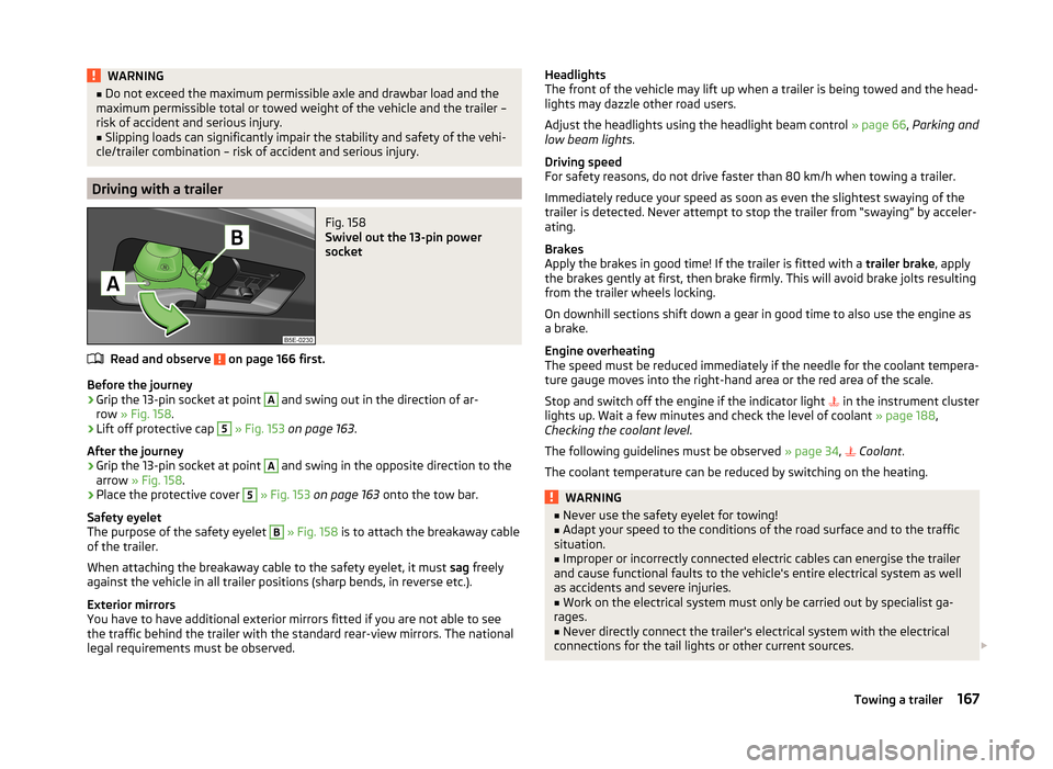
Fig. 158
Swivel out the 13-pin power
socket
Read and observe on page 166 first.
Before the journey
›
Grip the 13-pin socket at point
A
and swing out in the direction of ar-
row » Fig. 158 .
›
Lift off protective cap
5
» Fig. 153 on page 163 .
After the journey
›
Grip the 13-pin socket at point
A
and swing in the opposite direction to the
arrow » Fig. 158 .
›
Place the protective cover
5
» Fig. 153 on page 163 onto the tow bar.
Safety eyelet
The purpose of the safety eyelet
B
» Fig. 158 is to attach the breakaway cable
of the trailer.
When attaching the breakaway cable to the safety eyelet, it must sag freely
against the vehicle in all trailer positions (sharp bends, in reverse etc.).
Exterior mirrors
You have to have additional exterior mirrors fitted if you are not able to see
the traffic behind the trailer with the standard rear-view mirrors. The national
legal requirements must be observed.
Headlights
The front of the vehicle may lift up when a trailer is being towed and the head-
lights may dazzle other road users.
Adjust the headlights using the headlight beam control » page 66, Parking and
low beam lights .
Driving speed
For safety reasons, do not drive faster than 80 km/h when towing a trailer.
Immediately reduce your speed as soon as even the slightest swaying of the
trailer is detected. Never attempt to stop the trailer from “swaying” by acceler-
ating.
Brakes
Apply the brakes in good time! If the trailer is fitted with a trailer brake, apply
the brakes gently at first, then brake firmly. This will avoid brake jolts resulting
from the trailer wheels locking.
On downhill sections shift down a gear in good time to also use the engine as
a brake.
Engine overheating
The speed must be reduced immediately if the needle for the coolant tempera-
ture gauge moves into the right-hand area or the red area of the scale.
Stop and switch off the engine if the indicator light in the instrument cluster
lights up. Wait a few minutes and check the level of coolant » page 188,
Checking the coolant level .
The following guidelines must be observed » page 34,
Coolant
.
The coolant temperature can be reduced by switching on the heating.WARNING■ Never use the safety eyelet for towing!■Adapt your speed to the conditions of the road surface and to the traffic
situation.■
Improper or incorrectly connected electric cables can energise the trailer
and cause functional faults to the vehicle's entire electrical system as well
as accidents and severe injuries.
■
Work on the electrical system must only be carried out by specialist ga-
rages.
■
Never directly connect the trailer's electrical system with the electrical
connections for the tail lights or other current sources.
167Towing a trailer
Page 178 of 246
Cavity protectionRead and observe
and on page 173 first.
All the cavities of your vehicle which are at risk from corrosion are protected
for life by a layer of protective wax applied in the factory.
This wax protection does not need to be inspected or re-applied.
If any small amount of wax flow out of the cavities at high temperatures, these
must be removed with a plastic scraper and the stains cleaned using a petrole-
um cleaner.
WARNINGSafety regulations should be observed when using petroleum cleaner to re-
move wax – risk of fire!
Wheels
Read and observe
and on page 173 first.
Wheel rims
Also thoroughly wash the wheel rims when washing the vehicle on a regular
basis.
Regularly remove salt and brake abrasion, otherwise the rim material will be
corroded.
Damage to the paint layer on the wheel rims must be touched up immediately.
Light alloy wheels
After washing thoroughly and treat the wheel rims with a protective product
for light alloy wheels. Products which cause abrasion must not be used to
treat the wheel rims.
CAUTION
Severe layers of dirt on the wheels can also result in wheel imbalance. This
may show itself in the form of a wheel vibration which is transmitted to the
steering wheel which, in certain circumstances, can cause premature wear of
the steering. This means it is necessary to remove the dirt.Underbody protection
Read and observe
and on page 173 first.
The underside of your vehicle is protected for life against chemical and me-
chanical influences.
It is not possible to guarantee that the protective coating will not suffer any
damage as the vehicle is driven.
We recommend having the protective coating underneath the vehicle and the
chassis checked — preferably before the beginning of winter and at the end of
winter.
WARNINGNever use additional underbody protection or anti-corrosion agents for ex-
haust pipes, catalytic converters, diesel particle filters or heat shields.
When the engine reaches its operating temperature, these substances may ignite - risk of fire!
Taking care of the interior
Introduction
This chapter contains information on the following subjects:
Natural leather
177
Artificial leather, cloths and Alcantara ®
178
Seat covers
178
Seat belts
178
Regular and proper care help to retain the efficiency and
value of your vehicle.
We recommend using vehicle care products from ŠKODA Original Accessories.
These are available from ŠKODA Partners. The usage instructions on the pack-
age must be observed.
WARNING■ Vehicle care products may be harmful to your health if not used according
to the instructions.■
Always keep the vehicle care products safe from people who are not com-
pletely independent, e.g. children - there is a danger of poisoning!
176General Maintenance
Page 181 of 246
WARNING (Continued)■The seat belts must not be allowed to come into contact with corrosive
liquids (e.g. acids).■
Check the condition of all the seat belts on a regular basis. If any damage
to the belt webbing, seat belt connections, inertia reel or lock is detected,
the seat belt must be replaced by a specialist garage.
■
The seat belts must be fully dried before being rolled up.
Inspecting and replenishing
Fuel
Introduction
This chapter contains information on the following subjects:
Refuelling
180
Unleaded petrol
180
Diesel fuel
181
The correct grades of fuel for your vehicle are stated on a sticker affixed to the
inside of the fuel filler flap » Fig. 159 on page 180 -
.
WARNINGThe national legal requirements must be observed if carrying a spare canis-
ter in the vehicle. We do not recommend carrying any fuel canisters in your
vehicle for safety reasons. in the event of an accident, these canisters can
become damaged and fuel may escape – risk of fire!
CAUTION
■ Never drive until the fuel tank is completely empty! The irregular supply of
fuel can cause misfiring, which can result in considerable damage to parts of
the engine and the exhaust system.■
Immediately remove any fuel that has spilled onto the vehicle's paintwork –
risk of paint damage!
■
If the vehicle was not purchased in the country where it was intended to be
operated, you should check whether the fuel specified by the manufacturer is
offered in the country where the vehicle will be operated. You should also per-
haps check whether the manufacturer has recommended a different fuel for
operation of the vehicle in the corresponding country. Is this not the case, then
you must check whether it is permitted by the manufacturer to operate the ve-
hicle with another fuel type.
179Inspecting and replenishing
Page 182 of 246
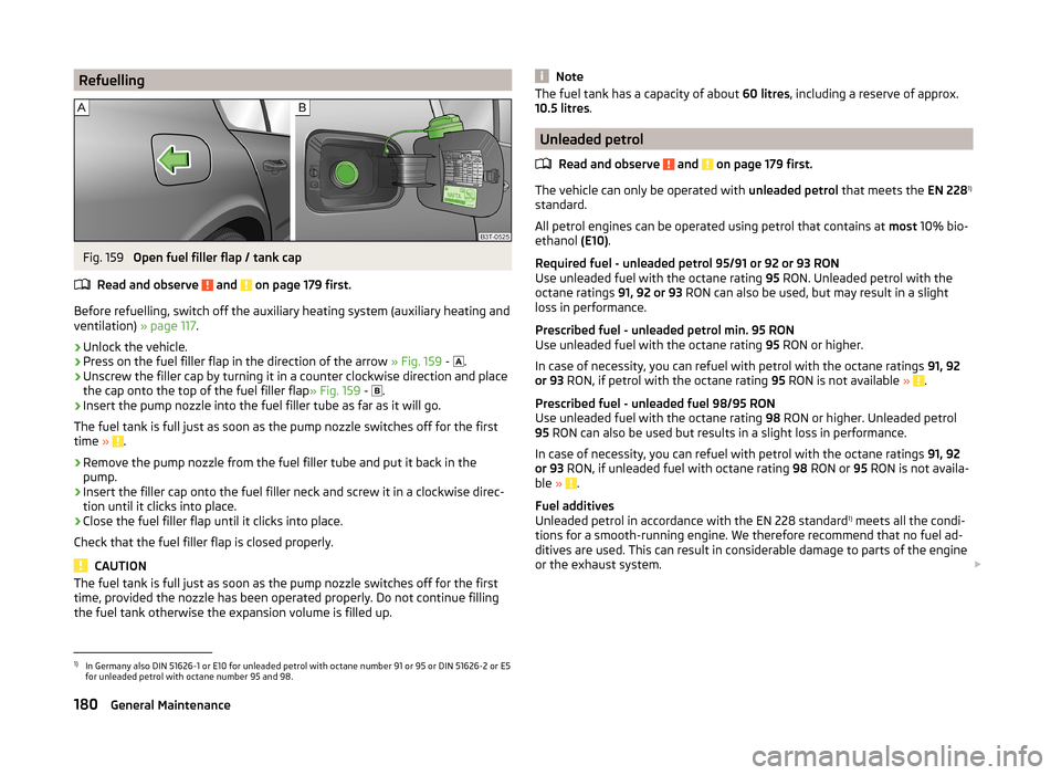
RefuellingFig. 159
Open fuel filler flap / tank cap
Read and observe
and on page 179 first.
Before refuelling, switch off the auxiliary heating system (auxiliary heating and ventilation) » page 117.
›
Unlock the vehicle.
›
Press on the fuel filler flap in the direction of the arrow » Fig. 159 -
.
›
Unscrew the filler cap by turning it in a counter clockwise direction and place
the cap onto the top of the fuel filler flap » Fig. 159 -
.
›
Insert the pump nozzle into the fuel filler tube as far as it will go.
The fuel tank is full just as soon as the pump nozzle switches off for the first
time »
.
›
Remove the pump nozzle from the fuel filler tube and put it back in the
pump.
›
Insert the filler cap onto the fuel filler neck and screw it in a clockwise direc-
tion until it clicks into place.
›
Close the fuel filler flap until it clicks into place.
Check that the fuel filler flap is closed properly.
CAUTION
The fuel tank is full just as soon as the pump nozzle switches off for the first
time, provided the nozzle has been operated properly. Do not continue filling
the fuel tank otherwise the expansion volume is filled up.NoteThe fuel tank has a capacity of about 60 litres, including a reserve of approx.
10.5 litres .
Unleaded petrol
Read and observe
and on page 179 first.
The vehicle can only be operated with unleaded petrol that meets the EN 2281)
standard.
All petrol engines can be operated using petrol that contains at most 10% bio-
ethanol (E10).
Required fuel - unleaded petrol 95/91 or 92 or 93 RON
Use unleaded fuel with the octane rating 95 RON. Unleaded petrol with the
octane ratings 91, 92 or 93 RON can also be used, but may result in a slight
loss in performance.
Prescribed fuel - unleaded petrol min. 95 RON
Use unleaded fuel with the octane rating 95 RON or higher.
In case of necessity, you can refuel with petrol with the octane ratings 91, 92
or 93 RON, if petrol with the octane rating 95 RON is not available »
.
Prescribed fuel - unleaded fuel 98/95 RON
Use unleaded fuel with the octane rating 98 RON or higher. Unleaded petrol
95 RON can also be used but results in a slight loss in performance.
In case of necessity, you can refuel with petrol with the octane ratings 91, 92
or 93 RON, if unleaded fuel with octane rating 98 RON or 95 RON is not availa-
ble »
.
Fuel additives
Unleaded petrol in accordance with the EN 228 standard 1)
meets all the condi-
tions for a smooth-running engine. We therefore recommend that no fuel ad-
ditives are used. This can result in considerable damage to parts of the engine
or the exhaust system.
1)
In Germany also DIN 51626-1 or E10 for unleaded petrol with octane number 91 or 95 or DIN 51626-2 or E5
for unleaded petrol with octane number 95 and 98.
180General Maintenance
Page 183 of 246
CAUTION■Even filling the tank with leaded petrol that does not meet the standards
once can lead to serious damage to parts of the exhaust system!■
If a fuel other than unleaded fuel which complies to the above mentioned
standards (e.g. leaded petrol) is used by mistake, do not start the engine or
switch on the ignition! Extensive damage to engine parts can occur! We rec-
ommend that you have the fuel system cleaned by a specialist garage.
CAUTION
■ If, in an emergency, the vehicle has to be refuelled with petrol of a lower oc-
tane number than the one prescribed, the journey must only be continued at
medium engine speeds and a low engine load. Driving at high engine revs or a
high engine load can severely damage the engine! Refuel using petrol of the
prescribed octane number as soon as possible.■
Engine parts can be damaged if petrol with a lower octane number than the
one prescribed is used.
■
Even in the event of an emergency, petrol of a lower octane number than 91
RON must not be used, otherwise the engine can be severely damaged!
CAUTION
■ In no case may fuel additives with metal components be used, especially not
with manganese and iron content. LRP(lead replacement petrol) fuels with
metallic components may not be used. There is a risk of causing considerable
damage to parts of the engine or exhaust system!■
Fuels with metallic content may not be used. There is a risk of causing con-
siderable damage to parts of the engine or exhaust system!
Note
■ Unleaded petrol that has a higher octane number than that required by the
engine can be used without limitations.■
On vehicles with prescribed unleaded petrol 95/91, 92 or 93 RON, the use of
petrol with a higher octane number than 95 RON does not result in a noticea-
ble power increase or a lower fuel consumption.
■
On vehicles using prescribed unleaded petrol of min. 95 RON, the use of pet-
rol with a higher octane number than 95 RON can increase the power and re-
duce fuel consumption.
Diesel fuel
Read and observe
and on page 179 first.
The vehicle can only be operated with diesel fuel that meets the EN 5901)
standard.
All diesel engines can be operated using diesel fuel with at most 7% biodiesel
(B7) 2)
.
On the Indian market, your vehicle will only be able to run on diesel fuel com-
pliant with standard IS 1460/Bharat IV. If diesel fuel which complies with this
standard is not available, you can refuel with diesel fuel according to standard
IS 1460/Bharat III in case of emergency.
Operation in winter - Winter-grade diesel fuel
In the cold season, only use “winter-grade diesel fuel” which will still operate properly even at a temperature of -20 °C.
It is often the case in countries with different climatic conditions that diesel
fuels available have a different temperature characteristic. ŠKODA Partners
and filling stations in the relevant country will be able to provide you with in-
formation regarding the diesel fuels available.
Preheating fuel
The vehicle is fitted with a fuel filter preheating system. This secures opera-
tion of a vehicle using diesel fuel down to an environmental temperature of
-25 °C.
Diesel fuel additives
Additives, so-called “flow improvers ” (petrol and similar agents) should not be
mixed with the diesel fuel. This can cause serious damage to engine or ex-
haust system parts.
1)
In Germany also DIN 51628, in Austria ÖNORM C 1590, in Russia GOST R 52368-2005 / EN 590:2004.
2)
In Germany according to the DIN 52638 standard, in Austria ÖNORM C 1590, in France EN 590.
181Inspecting and replenishing