lock SKODA SUPERB 2014 2.G / (B6/3T) Owner's Manual
[x] Cancel search | Manufacturer: SKODA, Model Year: 2014, Model line: SUPERB, Model: SKODA SUPERB 2014 2.G / (B6/3T)Pages: 246, PDF Size: 17.16 MB
Page 5 of 246
Table of Contents
Abbreviations
Safety
Passive Safety
6
General information
6
Correct and safe seated position
7
Seat belts
10
Using seat belts
10
Inertia reels and belt tensioners
13
Airbag system
14
Description of the airbag system
14
Airbag overview
15
Deactivating airbags
19
Transporting children safely
21
Child seat
21
Fastening systems
23
Operation
Cockpit
27
Overview
26
Instruments and Indicator Lights
28
Instrument cluster
28
Warning lights
32
Information system
39
Driver information system
39
Multifunction display (MFD)
41
MAXI DOT display
44
Service interval display
46
Unlocking and opening
48
Unlocking and locking
48
Anti-theft alarm system
54
Luggage compartment lid
55Electric boot lid (Superb Combi)57Electric power windows59
Electric sliding/tilting roof
62
Panoramic sliding/tilting roof (Superb Estate)
63
Lights and visibility
65
Lights
65
Interior lights
71
Visibility
73
Windscreen wipers and washers
75
Rear mirror
77
Seats and useful equipment
79
Adjusting the seats
79
Seat features
83
Practical equipment
86
Luggage compartment
95
Removable light (Superb Combi)
101
Variable loading floor in the luggage
compartment (Estate)
102
Extending variable loading floor with
integrated aluminium rails and faseting
elements (Superb Combi)
103
Net partition (Superb Combi)
105
Roof rack system
106
Air conditioning system
108
Heating, ventilation, cooling
108
Air conditioning system (manual air
conditioning system)
110
Climatronic (automatic air conditioning
system)
113
Auxiliary heating (auxiliary heating and
ventilation)
116
Communication and multimedia
119
General information
119
Universal telephone preinstallation GSM II
122
Universal telephone preinstallation GSM IIl
124
WLAN
127Voice control129Multimedia131
Driving
Starting-off and Driving
135
Starting and stopping the engine using the key
135
Starting and stopping the engine - KESSY
137
Brakes
140
Manual gear changing and pedals
141
Automatic gearbox
142
Running in
145
Economical driving and environmental
sustainability
146
Avoiding damage to your vehicle
149
Driving abroad
150
Assist systems
151
Brake assist systems
151
Parking aid
153
Park assist
154
Cruise Control System
158
START-STOP
159
Fatigue detection (break recommendation)
162
Towing a trailer
163
Towing device
163
Trailer
166
General Maintenance
Car care
169
Services, modifications, and technical
alterations
169
Washing your car
172
Taking care of your vehicle exterior
173
Taking care of the interior
1763Table of Contents
Page 6 of 246
Inspecting and replenishing179Fuel179
Engine compartment
182
Engine oil
185
Coolant
187
Brake fluid
189
Vehicle battery
189
Wheels
193
Tyres and wheel rims
193
Winter operation
198
Do-it-yourself
Emergency equipment and self-help
200
Emergency equipment
200
Changing a wheel
201
Tyre repair
204
Jump-starting
207
Towing the vehicle
208
Radio remote control
210
Emergency unlocking/locking
212
Emergency operation of the sliding/tilting
roof
213
Replacing windscreen wiper blades
214
Fuses and light bulbs
215
Fuses
215
Bulbs
219
Technical data
Technical data
224
Vehicle data
224
Index
4Table of Contents
Page 7 of 246
AbbreviationsAbbreviationDefinitionrpmEngine revolutions per minuteABSAnti-lock brake systemAFMulti-purpose vehiclesAHLAdaptive headlightsAGAutomatic gearboxAPNAccess Point Name - the name of an access point for the Wi-
Fi networkTCSTraction controlCO 2 in g/kmdischarged quantity of carbon dioxide in grams per driven
kilometerDPFDiesel particle filterDSGAutomatic double clutch gearboxDSRActive driver-steering recommendationEDLElectronic differential lockECEEconomic Commission for EuropeEPCEPC fault lightESCElectronic Stability ControlEUEuropean UnionFSIStratified petrol direct injectionGSMGroupe Spécial Mobile - a digital network of mobile devices
for the transmission of voice and dataHFPHands-free profile - connection of a mobile device by means
of its Bluetooth ®
profilekWKilowatt, measuring unit for the engine outputMGManual gearboxMFDMultifunction displayN1Panel van intended exclusively or mainly for the transporta-
tion of goodsNmNewton meter, measuring unit for the engine torqueAbbreviationDefinitionPINPersonal Identification Number - personal identification
number for the connection of electronic devices using Blue-
tooth ®
or WiFirSAPRemote SIM Access Profile - remote transmission of SIM da-
taSSPSimple Security Pairing - connection of two devices using
Bluetooth ®
profileTDI CRDiesel engine with turbocharging and common rail injection
systemTDI PDDiesel engine with injection system and unit injector injec-
tion systemTSATrailer stabilisationTSIPetrol engine with turbocharging and direct injectionUMTSUniversal Mobile Telecommunication System - the next evo-
lution of the GSM network (3G)WLANWireless Local Area Network - wireless connection of elec-
tronic devices for data transfer (WiFi)5Abbreviations
Page 10 of 246
WARNING■Always assume the correct seated position before setting off and do not
change this position while driving. Also advise your passengers to adopt
the correct seated position and not to change this position while the car is
moving.■
Maintain a distance of at least 25 cm from the steering wheel, and a dis-
tance of at least 10 cm between the legs and the dash panel at the height
of the knee airbag. Not maintaining this minimum distance will mean that
the airbag system will not be able to properly protect you - hazard!
■
When driving, hold the steering wheel with both hands firmly on the out-
er edge in the “9 o'clock” and “3 o'clock” position. Never hold the steering
wheel in the “12 o'clock” position or in any other way (e.g. in the middle or
inner edge of the steering wheel). In such cases, you could severely injure
the arms, hands and head when the driver airbag is deployed.
■
Ensure that there are no objects in the driver's footwell as they may get
caught behind the pedals when driving or applying the braking. You would
then no longer be able to operate the clutch, brake or acceleration pedals.
Adjusting the steering wheel position
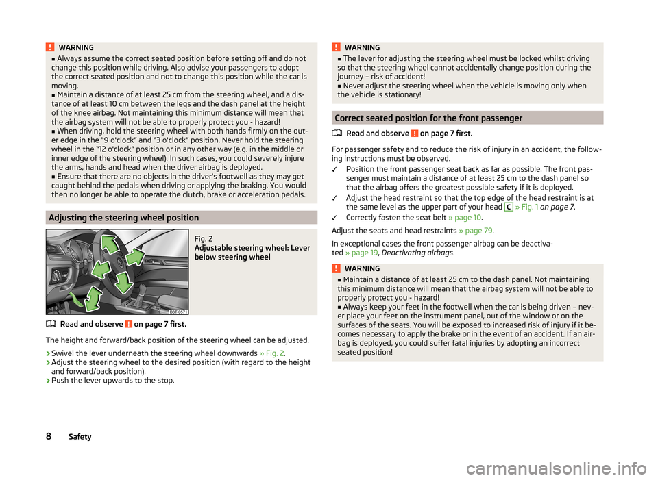
Fig. 2
Adjustable steering wheel: Lever
below steering wheel
Read and observe on page 7 first.
The height and forward/back position of the steering wheel can be adjusted.
›
Swivel the lever underneath the steering wheel downwards » Fig. 2.
›
Adjust the steering wheel to the desired position (with regard to the height
and forward/back position).
›
Push the lever upwards to the stop.
WARNING■ The lever for adjusting the steering wheel must be locked whilst driving
so that the steering wheel cannot accidentally change position during the
journey – risk of accident!■
Never adjust the steering wheel when the vehicle is moving only when
the vehicle is stationary!
Correct seated position for the front passenger
Read and observe
on page 7 first.
For passenger safety and to reduce the risk of injury in an accident, the follow-ing instructions must be observed.
Position the front passenger seat back as far as possible. The front pas-
senger must maintain a distance of at least 25 cm to the dash panel so
that the airbag offers the greatest possible safety if it is deployed.
Adjust the head restraint so that the top edge of the head restraint is at
the same level as the upper part of your head
C
» Fig. 1 on page 7 .
Correctly fasten the seat belt » page 10.
Adjust the seats and head restraints » page 79.
In exceptional cases the front passenger airbag can be deactiva-
ted » page 19 , Deactivating airbags .
WARNING■
Maintain a distance of at least 25 cm to the dash panel. Not maintaining
this minimum distance will mean that the airbag system will not be able to
properly protect you - hazard!■
Always keep your feet in the footwell when the car is being driven – nev-
er place your feet on the instrument panel, out of the window or on the
surfaces of the seats. You will be exposed to increased risk of injury if it be-
comes necessary to apply the brake or in the event of an accident. If an air-
bag is deployed, you could suffer fatal injuries by adopting an incorrect
seated position!
8Safety
Page 13 of 246
WARNING (Continued)■The lock tongue should only be inserted into the lock which is the correct
one for your seat. Wrong use of the safety belt will reduce its capacity to
protect and the risk of injury increases.■
The slot of the belt tongue must not be blocked, otherwise the belt
tongue will not lock in place properly.
■
Many layers of clothing and loose clothing (e. g. a winter coat over a jack-
et) do not allow you to be correctly seated and impairs proper operation of
the seat belts.
■
It is prohibited to use clamps or other objects to adjust seat belts (e. g. for
shortening the belts for smaller persons).
■
The seat belts for the rear seats can only fulfil their function reliably
when the seat backrests are correctly locked into position » page 85.
WARNINGInformation on the care and maintenance of the safety belts■The belt webbing must always be kept clean. Soiled belt webbing may im-
pair proper operation of the inertia reel » page 178.■
The seat belts must not be removed or changed in any way. Do not at-
tempt to repair the seat belts yourself.
■
Check the condition of all the seat belts on a regular basis. If any damage
to the seat belts, seat belt connections, inertia reel or the lock is detected,
the relevant seat belt must be replaced by a specialist garage.
■
Damaged seat belts which have been subjected to stress in an accident
and were therefore stretched, must be replaced – this is best done by a
specialist garage. The anchorage points of the belts must also be inspec-
ted. The anchorage points for the belts should also be checked.
Note
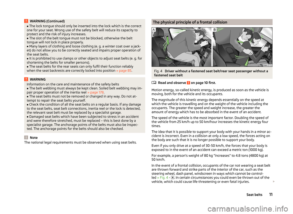
The national legal requirements must be observed when using seat belts.The physical principle of a frontal collisionFig. 4
Driver without a fastened seat belt/rear seat passenger without a
fastened seat belt
Read and observe
on page 10 first.
Motion energy, so-called kinetic energy, is produced as soon as the vehicle is
moving, both for the vehicle and its occupants.
The magnitude of this kinetic energy depends essentially on the speed at
which the vehicle is travelling and on the weight of the vehicle including the
occupants. The greater the speed and weight increase, the greater the
amount of energy which has to be absorbed in the event of an accident.
The speed of the vehicle is the most important factor. Doubling the speed of
the vehicle from 25 km/h up to 50 km/hour increases the kinetic energy four
times.
The idea that it is possible to support your body with your hands in a minor ac-
cident is incorrect. Even in a collision at only a low speed, the forces acting on
the body are such that it is no longer possible to support your body.
Even if you only drive at a speed of 30-50 km/h, the forces that your body is
exposed to in the event of an accident can exceed a metric ton (1000 kg).
For example, a person's weight of 80 kg “increases” to 4.8 tons (4800 kg) at
50 km/h.
In the event of a frontal collision, occupants of the car not wearing a seat belt
are thrown forward and strike parts of the interior of the car, such as the
steering wheel, dash panel, windscreen in ways which cannot be control-
led » Fig. 4 -
. In certain circumstances you could even be thrown out of the
vehicle, which could cause life threatening or even fatal injuries.
11Seat belts
Page 14 of 246
It is also important that rear passengers fasten their seat belts, as they could
otherwise be thrown through the vehicle in an uncontrolled manner in the
event of an accident.
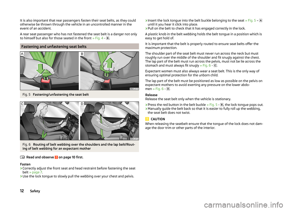
A rear seat passenger who has not fastened the seat belt is a danger not only
to himself but also for those seated in the front » Fig. 4 -
.
Fastening and unfastening seat belts
Fig. 5
Fastening/unfastening the seat belt
Fig. 6
Routing of belt webbing over the shoulders and the lap belt/Rout-
ing of belt webbing for an expectant mother
Read and observe
on page 10 first.
Fasten
›
Correctly adjust the front seat and head restraint before fastening the seat
belt » page 7 .
›
Use the lock tongue to slowly pull the webbing over your chest and pelvis.
›Insert the lock tongue into the belt buckle belonging to the seat
» Fig. 5 –
until it you hear it click into place.›
Pull on the belt to check that it has engaged correctly in the lock.
A plastic knob in the belt webbing holds the belt tongue in a position which is
easy to get hold of.
It is important that the belt is properly routed to ensure seat belts offer the
maximum protection.
The shoulder part of the seat belt must never run across the neck but must
roughly run over the middle of the shoulder and fit snugly against the chest.
The lap part of the belt must run across the pelvis, must not be lie across the
stomach and must always fit snugly » Fig. 6 -
.
Expectant women must also always wear a seat belt. This is the only way of ensuring optimal protection for the unborn child.
The lap part of the belt must be positioned as low as possible on the pelvis on expectant mothers to avoid exerting any pressure on the lower abdo-
men » Fig. 6 -
.
Release
Release the seat belt only when the vehicle is stationary.
›
Press the red button in the belt buckle » Fig. 5 -
, the lock tongue pops out.
›
Manually guide the belt back so that it is easier to fully roll up the webbing,
the seat belt does not twist.
CAUTION
When releasing the seatbelt ensure that the tongue of the lock does not dam-
age the door trim or other parts of the interior.12Safety
Page 15 of 246
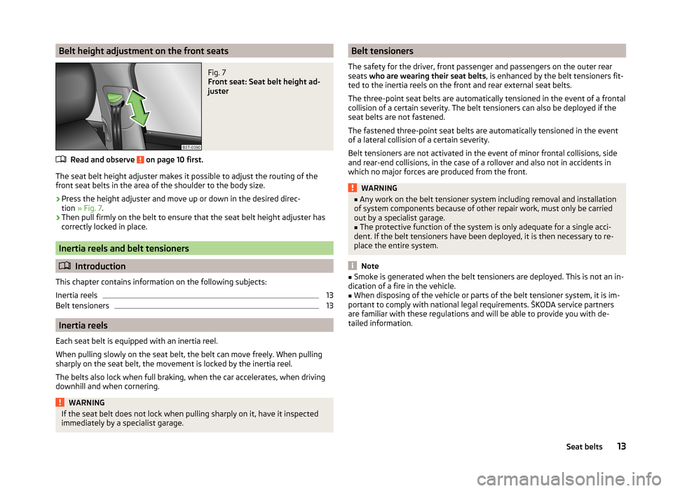
Belt height adjustment on the front seatsFig. 7
Front seat: Seat belt height ad-
juster
Read and observe on page 10 first.
The seat belt height adjuster makes it possible to adjust the routing of the
front seat belts in the area of the shoulder to the body size.
›
Press the height adjuster and move up or down in the desired direc-
tion » Fig. 7 .
›
Then pull firmly on the belt to ensure that the seat belt height adjuster has
correctly locked in place.
Inertia reels and belt tensioners
Introduction
This chapter contains information on the following subjects:
Inertia reels
13
Belt tensioners
13
Inertia reels
Each seat belt is equipped with an inertia reel.
When pulling slowly on the seat belt, the belt can move freely. When pulling
sharply on the seat belt, the movement is locked by the inertia reel.
The belts also lock when full braking, when the car accelerates, when driving
downhill and when cornering.
WARNINGIf the seat belt does not lock when pulling sharply on it, have it inspected
immediately by a specialist garage.Belt tensioners
The safety for the driver, front passenger and passengers on the outer rear
seats who are wearing their seat belts , is enhanced by the belt tensioners fit-
ted to the inertia reels on the front and rear external seat belts.
The three-point seat belts are automatically tensioned in the event of a frontal
collision of a certain severity. The belt tensioners can also be deployed if the
seat belts are not fastened.
The fastened three-point seat belts are automatically tensioned in the event
of a lateral collision of a certain severity.
Belt tensioners are not activated in the event of minor frontal collisions, side
and rear-end collisions, in the case of a rollover and also not in accidents in
which no major forces are produced from the front.WARNING■ Any work on the belt tensioner system including removal and installation
of system components because of other repair work, must only be carried
out by a specialist garage.■
The protective function of the system is only adequate for a single acci-
dent. If the belt tensioners have been deployed, it is then necessary to re-
place the entire system.
Note
■ Smoke is generated when the belt tensioners are deployed. This is not an in-
dication of a fire in the vehicle.■
When disposing of the vehicle or parts of the belt tensioner system, it is im-
portant to comply with national legal requirements. ŠKODA service partners
are familiar with these regulations and will be able to provide you with de-
tailed information.
13Seat belts
Page 17 of 246
The airbags are not deployed in the case of minor frontal and side collisions,
rear-end collisions, tilting of the vehicle and vehicle rollover.
Deployment factors
It is not possible to generally determine which deployment conditions apply to
the airbag system in every situation. An important role is played by factors
such as the type of object that the vehicle hits (hard/soft), the impact angle,
vehicle speed etc.
A decisive factor for the deployment of the airbags is the deceleration which
occurs. The control unit analyses the nature of the collision and activates the
relevant restraint system.
If the vehicle deceleration which occurs and is measured during the collision
remains below the prescribed reference values specified in the control unit,
the airbags are not deployed although the vehicle may well suffer severe dam-
age to the bodywork as a consequence of the accident.
The following airbags will be deployed in the event of a severe frontal
collision.
› Driver’s front airbag.
› Front passenger airbag.
› Driver’s knee airbag.
The following airbags will be deployed in the event of a severe side collision.
› Front side airbag on the side of the accident.
› Rear side airbag on the side of the accident.
› Head airbags on the side of the accident.
In the event of an accident in which the airbags are deployed:
› the interior lighting comes on (if the switch for the interior light is in the door
contact position),
› the hazard warning light is switched on;
› all the doors are unlocked;
› the fuel supply to the engine is interrupted.
Airbag overview
Introduction
This chapter contains information on the following subjects:
Front airbags
15
Driver’s knee airbag
16Side airbags17Head airbags18
Front airbags
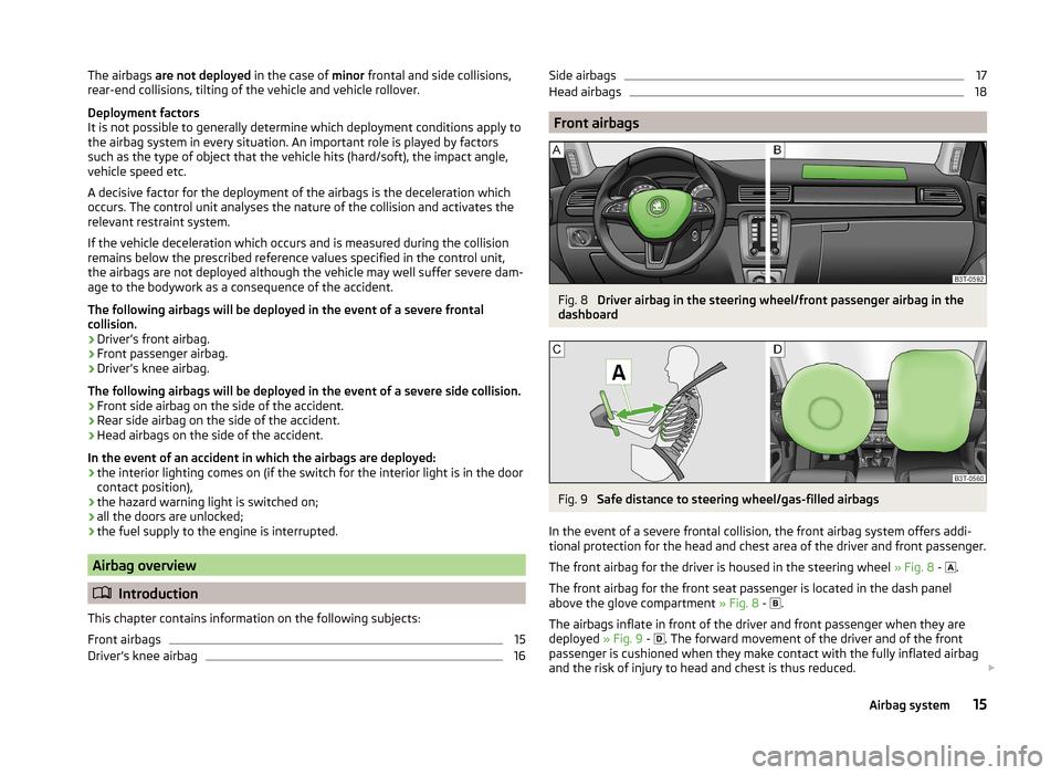
Fig. 8
Driver airbag in the steering wheel/front passenger airbag in the
dashboard
Fig. 9
Safe distance to steering wheel/gas-filled airbags
In the event of a severe frontal collision, the front airbag system offers addi-
tional protection for the head and chest area of the driver and front passenger.
The front airbag for the driver is housed in the steering wheel » Fig. 8 -
.
The front airbag for the front seat passenger is located in the dash panel
above the glove compartment » Fig. 8 -
.
The airbags inflate in front of the driver and front passenger when they are
deployed » Fig. 9 -
. The forward movement of the driver and of the front
passenger is cushioned when they make contact with the fully inflated airbag
and the risk of injury to head and chest is thus reduced.
15Airbag system
Page 25 of 246
WARNING■Children must never be seated with their head in the deployment area of
the side airbag – risk of injury!■
Do not place any objects within the deployment area of the side airbags –
risk of injury!
Classification of child seats
Read and observe
and on page 21 first.
Classification of child seats according to the ECE-R 44 standard.
GroupWeight of the childApproximate age0up to 10 kgup to 9 months0+up to 13 kgup to 18 months19-18 kgup to 4 years215-25 kgup to 7 years322-36 kgover 7 years
Use of child seats fastened with a seat belt Read and observe
and on page 21 first.
Overview of the usability of child seats fastened with a seat belt on each of
the seats in accordance with the ECE-R 16 standard.
GroupFront passenger seatRear seatsoutsideRear seatCenter0
up to 10 kgUUU0+
up to 13 kgUUU1
9-18 kgUUU2
15-25 kgUUU3
22-36 kgUUU“Universal” child seat category - a child seat designed to be attached to the seat using the seat belt.
Fastening systems
Introduction
This chapter contains information on the following subjects:
Anchor eyelets for the ISOFIX system
23
Use of child seats with the ISOFIX system
24
Anchor eyelets for the TOP TETHER system
24
Anchor eyelets for the ISOFIX system
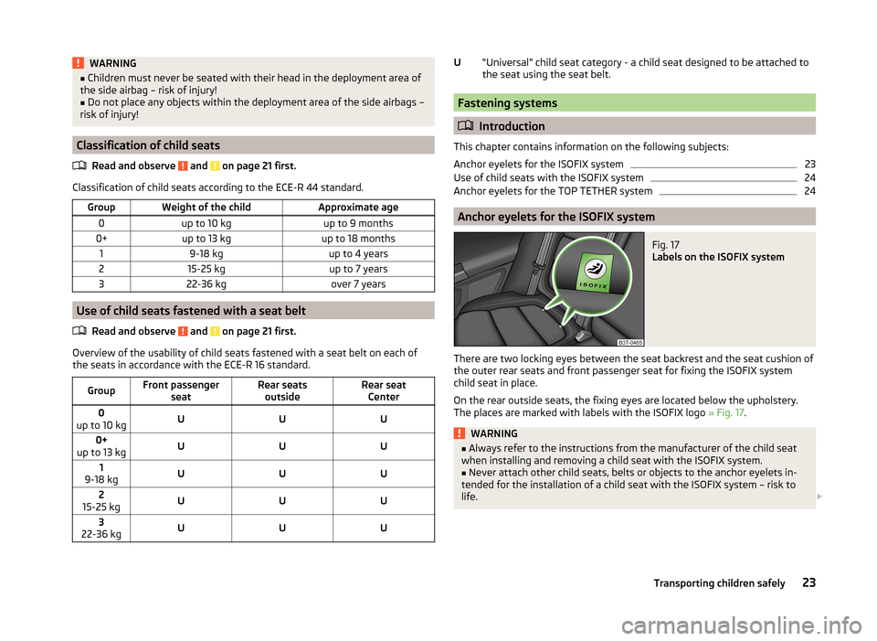
Fig. 17
Labels on the ISOFIX system
There are two locking eyes between the seat backrest and the seat cushion of
the outer rear seats and front passenger seat for fixing the ISOFIX system
child seat in place.
On the rear outside seats, the fixing eyes are located below the upholstery.
The places are marked with labels with the ISOFIX logo » Fig. 17.
WARNING■
Always refer to the instructions from the manufacturer of the child seat
when installing and removing a child seat with the ISOFIX system.■
Never attach other child seats, belts or objects to the anchor eyelets in-
tended for the installation of a child seat with the ISOFIX system – risk to
life.
U23Transporting children safely
Page 27 of 246
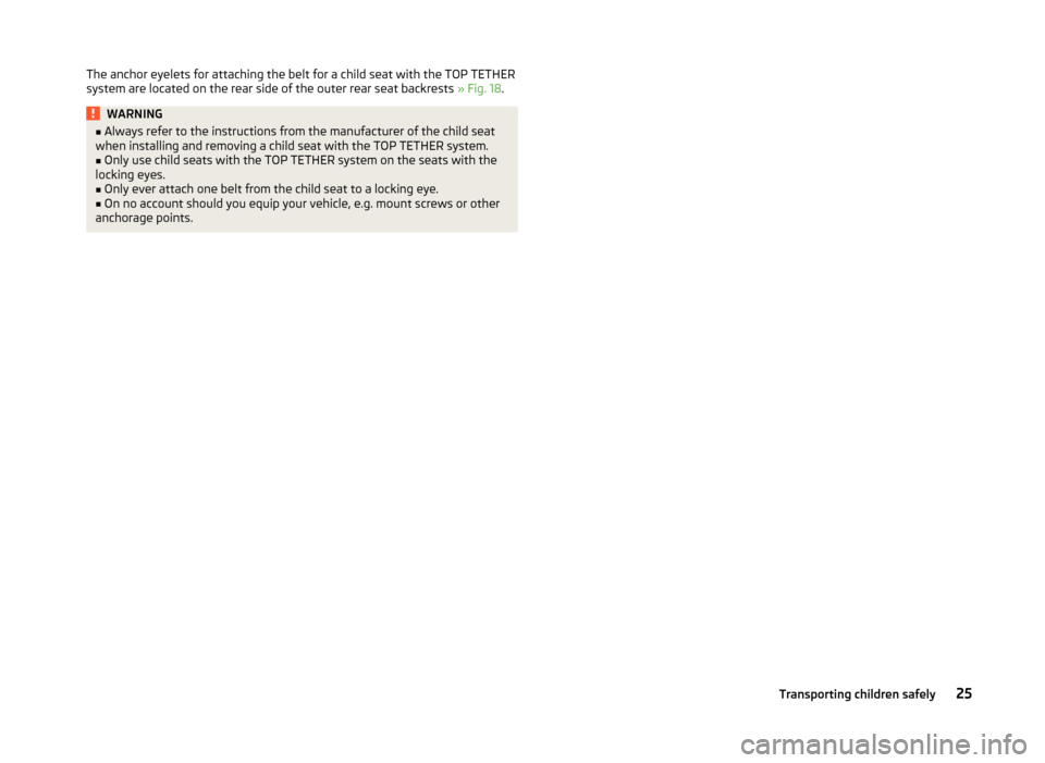
The anchor eyelets for attaching the belt for a child seat with the TOP TETHER
system are located on the rear side of the outer rear seat backrests » Fig. 18.WARNING■
Always refer to the instructions from the manufacturer of the child seat
when installing and removing a child seat with the TOP TETHER system.■
Only use child seats with the TOP TETHER system on the seats with the
locking eyes.
■
Only ever attach one belt from the child seat to a locking eye.
■
On no account should you equip your vehicle, e.g. mount screws or other
anchorage points.
25Transporting children safely