engine SKODA SUPERB 2016 3.G / (B8/3V) Manual PDF
[x] Cancel search | Manufacturer: SKODA, Model Year: 2016, Model line: SUPERB, Model: SKODA SUPERB 2016 3.G / (B8/3V)Pages: 336, PDF Size: 53.89 MB
Page 289 of 336
›For vehicles with
manual transmission , set the lever in the neutral position.›On vehicles with automatic transmission , place the selector lever in the P
position.›
Start the engine.
›
Plug the connector
6
into 12 volt socket » page 96.
›
Switch on the air compressor with the ON and OFF switch
9
.
›
Once a tyre inflation pressure of 2.0-2.5 bar is reached, turn off the air com-
pressor. Maximum run time of 6 minutes » .
›
If you cannot reach an air pressure of 2.0 - 2.5 bar, unscrew the tyre inflation
hose
7
from the tyre valve.
›
Drive the vehicle approx. 10 metres forwards or backwards to allow the seal-
ing agent to “distribute” in the tyre.
›
Firmly screw the tyre inflation hose
7
back onto the tyre valve and repeat
the inflation process.
›
Stick the corresponding sticker
1
on the dashboard in the driver's field of
view.
Once a tyre inflation pressure of 2.0 – 2.5 bar is achieved, continue the journey
at a maximum speed of 80 km/h (50 mph).
WARNING■ If the tire does not inflate at least. 2.0 bar, the damage is too great. The
sealing agent cannot be used to seal the tyre. Stop driving! Seek help
from a specialist garage.■
The tyre inflation hose and air compressor may get hot as the tyre is be-
ing inflated – risk of burning.
CAUTION
Switch off the air compressor after running 6 minutes at the most – risk of
overheating! Allow the air compressor to cool a few minutes before switching
it on again.
Information for driving with repaired tyres
Read and observe
on page 285 first.
The inflation pressure of the repaired tyre must be checked after driving for 10
minutes.
If the tyre inflation pressure is 1.3 bar or less
›
The tyre cannot be properly sealed with the breakdown kit.
Do not drive
the vehicle! Seek help from a specialist garage.
If the tyre inflation pressure is 1.3 bar or more›Set the tyre pressure back to the correct value » page 277.›
Continue driving carefully to the nearest specialist garage at a maximum
speed of 80 km/h (50 mph).
WARNINGA tyre filled with sealant has the same driving characteristics as a standard
tyre. The following guidelines must be observed.■
Do not drive faster than 80 km/h (50 mph).
■
Avoid accelerating at full throttle, sharp braking and fast cornering.
Jump-starting
Introduction
This chapter contains information on the following subjects:
Start using the battery from another vehicle
288WARNING■ The following instructions must be followed at all times when working on
the engine compartment » page 268.■
When handling the vehicle battery, the following warnings must be ob-
served » page 273 .
■
A discharged vehicle battery may already freeze at temperatures just be-
low 0 °C. If the battery is frozen, do not carry out a jump start with the bat-
tery of another vehicle – risk of explosion!
■
Never jump-start vehicle batteries with an acid level that is too low – risk
of explosion and caustic burns!
287Emergency equipment and self-help
Page 290 of 336
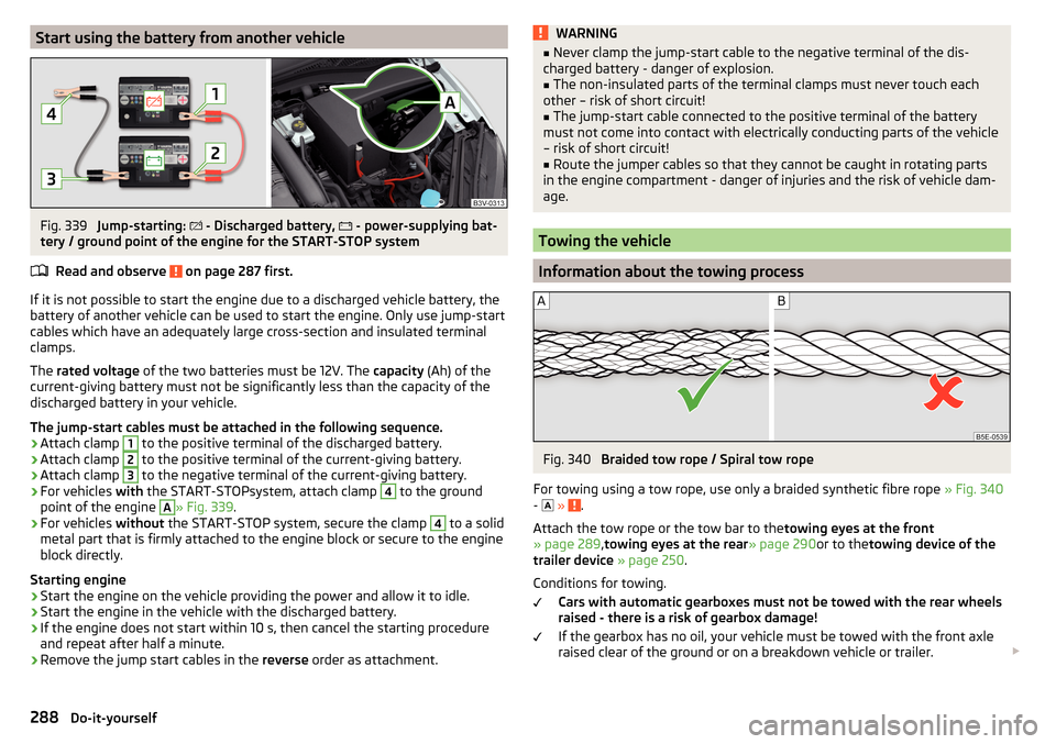
Start using the battery from another vehicleFig. 339
Jump-starting:
- Discharged battery,
- power-supplying bat-
tery / ground point of the engine for the START-STOP system
Read and observe
on page 287 first.
If it is not possible to start the engine due to a discharged vehicle battery, the
battery of another vehicle can be used to start the engine. Only use jump-start
cables which have an adequately large cross-section and insulated terminal
clamps.
The rated voltage of the two batteries must be 12V. The capacity (Ah) of the
current-giving battery must not be significantly less than the capacity of the
discharged battery in your vehicle.
The jump-start cables must be attached in the following sequence.
›
Attach clamp
1
to the positive terminal of the discharged battery.
›
Attach clamp
2
to the positive terminal of the current-giving battery.
›
Attach clamp
3
to the negative terminal of the current-giving battery.
›
For vehicles with the START-STOPsystem, attach clamp
4
to the ground
point of the engine
A
» Fig. 339 .
›
For vehicles without the START-STOP system, secure the clamp
4
to a solid
metal part that is firmly attached to the engine block or secure to the engine
block directly.
Starting engine
›
Start the engine on the vehicle providing the power and allow it to idle.
›
Start the engine in the vehicle with the discharged battery.
›
If the engine does not start within 10 s, then cancel the starting procedure
and repeat after half a minute.
›
Remove the jump start cables in the reverse order as attachment.
WARNING■
Never clamp the jump-start cable to the negative terminal of the dis-
charged battery - danger of explosion.■
The non-insulated parts of the terminal clamps must never touch each
other – risk of short circuit!
■
The jump-start cable connected to the positive terminal of the battery
must not come into contact with electrically conducting parts of the vehicle
– risk of short circuit!
■
Route the jumper cables so that they cannot be caught in rotating parts
in the engine compartment - danger of injuries and the risk of vehicle dam-
age.
Towing the vehicle
Information about the towing process
Fig. 340
Braided tow rope / Spiral tow rope
For towing using a tow rope, use only a braided synthetic fibre rope » Fig. 340
-
»
.
Attach the tow rope or the tow bar to the towing eyes at the front
» page 289 ,towing eyes at the rear » page 290or to thetowing device of the
trailer device » page 250 .
Conditions for towing. Cars with automatic gearboxes must not be towed with the rear wheels
raised - there is a risk of gearbox damage!
If the gearbox has no oil, your vehicle must be towed with the front axle
raised clear of the ground or on a breakdown vehicle or trailer.
288Do-it-yourself
Page 291 of 336
The maximum towing speed is 50 km/h.
The vehicle must be transported on a special breakdown vehicle or trailer
if it is not possible to tow in the vehicle in the way described or if the tow-
ing distance is greater than 50 km.
Driver of the tow vehicle›
On vehicles with manual transmission , engage gear slowly when starting.
›
On vehicles with automatic transmission , accelerate with particular care.
›
Only then approach correctly when the rope is taut.
Driver of the towed vehicle
›
If possible, the vehicle should be towed with the engine running. Operate the
brake booster and power steering only if the engine is running, otherwise
the brake pedal must be depressed more strongly and more power has to be
directed to the steering.
›
If it is not possible to start the engine, switch on the ignition so that the
steering wheel is not locked and so that the turn signal lights, windscreen
wipers and windscreen washer system can be used.
›
Take the vehicle out of gear or move the selector lever into position N if the
vehicle is fitted with an automatic gearbox.
›
Always keep the tow rope taut during the towing procedure.
WARNING■ Wound tow ropes must not be used for towing » Fig. 340- , the towing
eye may unscrew out of the vehicle - risk of accident.■
Ensure tow rope is not twisted - risk of accident.
CAUTION
■ Do not tow-start the engine – risk of damaging the engine! The battery from
another vehicle can be used as a jump-start aid » page 287, Jump-starting .■
In the case of off-road towing manoeuvres, for both vehicles there is the risk
that the fastening parts could be overloaded and damaged.
Note
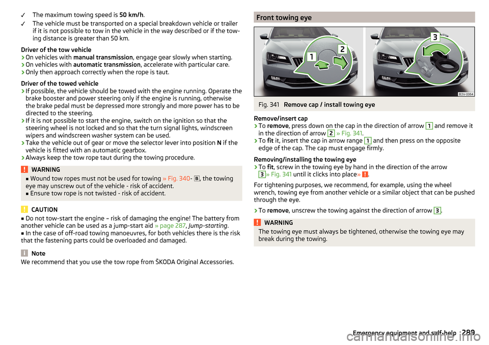
We recommend that you use the tow rope from ŠKODA Original Accessories.Front towing eyeFig. 341
Remove cap / install towing eye
Remove/insert cap
›
To remove , press down on the cap in the direction of arrow
1
and remove it
in the direction of arrow
2
» Fig. 341 .
›
To fit it, insert the cap in arrow range
1
and then press on the opposite
edge of the cap. The cap must engage firmly.
Removing/installing the towing eye
›
To fit, screw in the towing eye by hand in the direction of the arrow
3
» Fig. 341 until it clicks into place » .
For tightening purposes, we recommend, for example, using the wheel
wrench, towing eye from another vehicle or a similar object that can be pushed
through the eye.
›
To remove , unscrew the towing against the direction of arrow
3
.
WARNINGThe towing eye must always be tightened, otherwise the towing eye may
break during the towing.289Emergency equipment and self-help
Page 297 of 336
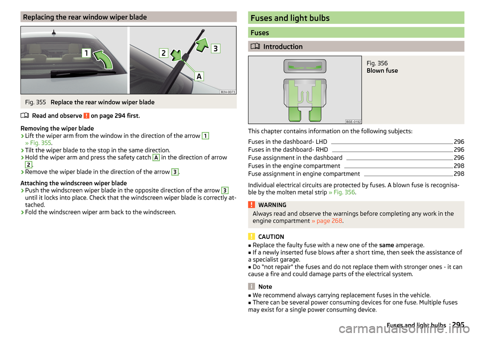
Replacing the rear window wiper bladeFig. 355
Replace the rear window wiper blade
Read and observe
on page 294 first.
Removing the wiper blade
›
Lift the wiper arm from the window in the direction of the arrow
1
» Fig. 355 .
›
Tilt the wiper blade to the stop in the same direction.
›
Hold the wiper arm and press the safety catch
A
in the direction of arrow
2
.
›
Remove the wiper blade in the direction of the arrow
3
.
Attaching the windscreen wiper blade
›
Push the windscreen wiper blade in the opposite direction of the arrow
3
until it locks into place. Check that the windscreen wiper blade is correctly at-
tached.
›
Fold the windscreen wiper arm back to the windscreen.
Fuses and light bulbs
Fuses
Introduction
Fig. 356
Blown fuse
This chapter contains information on the following subjects:
Fuses in the dashboard- LHD
296
Fuses in the dashboard- RHD
296
Fuse assignment in the dashboard
296
Fuses in the engine compartment
298
Fuse assignment in engine compartment
298
Individual electrical circuits are protected by fuses. A blown fuse is recognisa-
ble by the molten metal strip » Fig. 356.
WARNINGAlways read and observe the warnings before completing any work in the
engine compartment » page 268.
CAUTION
■
Replace the faulty fuse with a new one of the same amperage.■If a newly inserted fuse blows after a short time, then seek the assistance of
a specialist garage.■
Do “not repair” the fuses and do not replace them with stronger ones - it can
cause a fire and could damage parts of the electrical system.
Note
■ We recommend always carrying replacement fuses in the vehicle.■There can be several power consuming devices for one fuse. Multiple fuses
may exist for a single power consuming device.295Fuses and light bulbs
Page 298 of 336
Fuses in the dashboard- LHDFig. 357
Storage compartment on the
driver's side
Read and observe and on page 295 first.
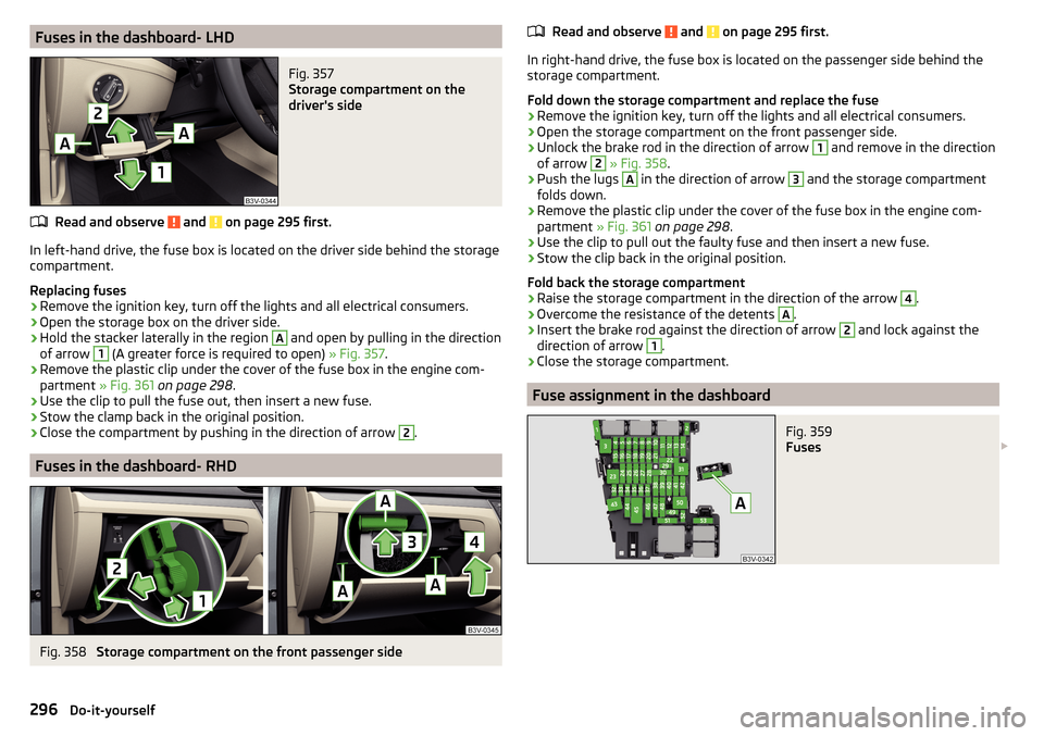
In left-hand drive, the fuse box is located on the driver side behind the storage compartment.
Replacing fuses
›
Remove the ignition key, turn off the lights and all electrical consumers.
›
Open the storage box on the driver side.
›
Hold the stacker laterally in the region
A
and open by pulling in the direction
of arrow
1
(A greater force is required to open) » Fig. 357.
›
Remove the plastic clip under the cover of the fuse box in the engine com-
partment » Fig. 361 on page 298 .
›
Use the clip to pull the fuse out, then insert a new fuse.
›
Stow the clamp back in the original position.
›
Close the compartment by pushing in the direction of arrow
2
.
Fuses in the dashboard- RHD
Fig. 358
Storage compartment on the front passenger side
Read and observe and on page 295 first.
In right-hand drive, the fuse box is located on the passenger side behind the
storage compartment.
Fold down the storage compartment and replace the fuse
›
Remove the ignition key, turn off the lights and all electrical consumers.
›
Open the storage compartment on the front passenger side.
›
Unlock the brake rod in the direction of arrow
1
and remove in the direction
of arrow
2
» Fig. 358 .
›
Push the lugs
A
in the direction of arrow
3
and the storage compartment
folds down.
›
Remove the plastic clip under the cover of the fuse box in the engine com-
partment » Fig. 361 on page 298 .
›
Use the clip to pull out the faulty fuse and then insert a new fuse.
›
Stow the clip back in the original position.
Fold back the storage compartment
›
Raise the storage compartment in the direction of the arrow
4
.
›
Overcome the resistance of the detents
A
.
›
Insert the brake rod against the direction of arrow
2
and lock against the
direction of arrow
1
.
›
Close the storage compartment.
Fuse assignment in the dashboard
Fig. 359
Fuses
296Do-it-yourself
Page 300 of 336
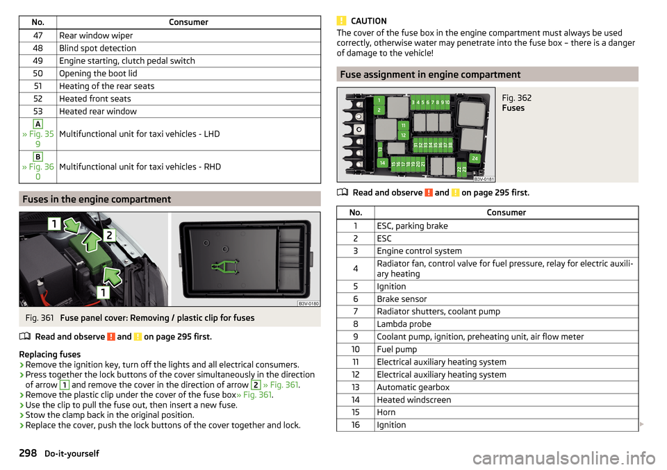
No.Consumer47Rear window wiper48Blind spot detection49Engine starting, clutch pedal switch50Opening the boot lid51Heating of the rear seats52Heated front seats53Heated rear windowA
» Fig. 359Multifunctional unit for taxi vehicles - LHD
B
» Fig. 36 0Multifunctional unit for taxi vehicles - RHD
Fuses in the engine compartment
Fig. 361
Fuse panel cover: Removing / plastic clip for fuses
Read and observe
and on page 295 first.
Replacing fuses
›
Remove the ignition key, turn off the lights and all electrical consumers.
›
Press together the lock buttons of the cover simultaneously in the direction
of arrow
1
and remove the cover in the direction of arrow
2
» Fig. 361 .
›
Remove the plastic clip under the cover of the fuse box » Fig. 361.
›
Use the clip to pull the fuse out, then insert a new fuse.
›
Stow the clamp back in the original position.
›
Replace the cover, push the lock buttons of the cover together and lock.
CAUTIONThe cover of the fuse box in the engine compartment must always be used
correctly, otherwise water may penetrate into the fuse box – there is a danger
of damage to the vehicle!
Fuse assignment in engine compartment
Fig. 362
Fuses
Read and observe and on page 295 first.
No.Consumer1ESC, parking brake2ESC3Engine control system4Radiator fan, control valve for fuel pressure, relay for electric auxili-
ary heating5Ignition6Brake sensor7Radiator shutters, coolant pump8Lambda probe9Coolant pump, ignition, preheating unit, air flow meter10Fuel pump11Electrical auxiliary heating system12Electrical auxiliary heating system13Automatic gearbox14Heated windscreen15Horn16Ignition 298Do-it-yourself
Page 301 of 336
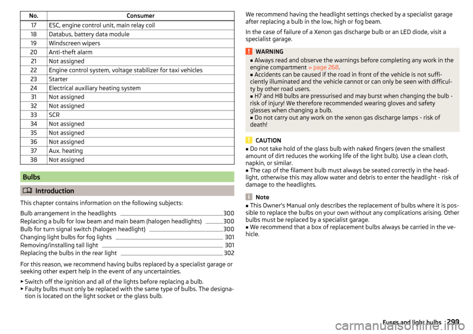
No.Consumer17ESC, engine control unit, main relay coil18Databus, battery data module19Windscreen wipers20Anti-theft alarm21Not assigned22Engine control system, voltage stabilizer for taxi vehicles23Starter24Electrical auxiliary heating system31Not assigned32Not assigned33SCR34Not assigned35Not assigned36Not assigned37Aux. heating38Not assigned
Bulbs
Introduction
This chapter contains information on the following subjects:
Bulb arrangement in the headlights
300
Replacing a bulb for low beam and main beam (halogen headlights)
300
Bulb for turn signal switch (halogen headlight)
300
Changing light bulbs for fog lights
301
Removing/installing tail light
301
Replacing the bulbs in the rear light
302
For this reason, we recommend having bulbs replaced by a specialist garage or
seeking other expert help in the event of any uncertainties.
▶ Switch off the ignition and all of the lights before replacing a bulb.
▶ Faulty bulbs must only be replaced with the same type of bulbs. The designa-
tion is located on the light socket or the glass bulb.
We recommend having the headlight settings checked by a specialist garage
after replacing a bulb in the low, high or fog beam.
In the case of failure of a Xenon gas discharge bulb or an LED diode, visit a
specialist garage.WARNING■ Always read and observe the warnings before completing any work in the
engine compartment » page 268.■
Accidents can be caused if the road in front of the vehicle is not suffi-
ciently illuminated and the vehicle cannot or can only be seen with difficul-
ty by other road users.
■
H7 and H8 bulbs are pressurised and may burst when changing the bulb -
risk of injury! We therefore recommended wearing gloves and safety
glasses when changing a bulb.
■
Do not carry out any work on the xenon gas discharge lamps - risk of
death!
CAUTION
■ Do not take hold of the glass bulb with naked fingers (even the smallest
amount of dirt reduces the working life of the light bulb). Use a clean cloth,
napkin, or similar.■
The cap of the filament bulb must always be seated correctly in the head-
light, otherwise this may allow water and debris to enter the headlight - risk of
damage to the headlights.
Note
■ This Owner's Manual only describes the replacement of bulbs where it is pos-
sible to replace the bulbs on your own without any complications arising. Other
bulbs must be replaced by a specialist garage.■
We recommend that a box of replacement bulbs always be carried in the ve-
hicle.
299Fuses and light bulbs
Page 305 of 336
Technical data
Technical data
Basic vehicle data
Introduction
This chapter contains information on the following subjects:
Vehicle data
303
Operating weight
304
Payload
305
Measurement of fuel consumption and CO 2 emissions according to ECE
Regulations and EU Directives
305
Dimensions - Superb
306
Dimensions - Superb estate
307
Overhang angle
308
The details given in the vehicle's technical documentation always take prece-
dence over the details in the Owner's Manual.
The listed performance values were determined without performance-reduc- ing equipment, e.g. air conditioning system.
The values given have been determined in accordance with the rules and con-
ditions specified in statutory or technical regulations for determining opera-
tional and technical data for motor vehicles.
The values listed are for the basic model without any optional equipment.
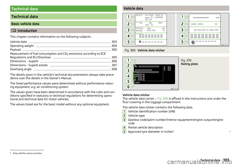
Vehicle dataFig. 369
Vehicle data sticker
Fig. 370
Rating plate
Vehicle data sticker
The vehicle data carrier » Fig. 369 is affixed in the instructions and under the
floor covering in the luggage compartment.
The vehicle data sticker contains the following data. Vehicle identification number (VIN)
Vehicle type
Gearbox code/paint number/interior equipment/engine output/engine
code
Partial vehicle description
Approved tyre diameter in inches 1)
123451)
Only valid for some countries.
303Technical data
Page 306 of 336
The approved tyres and rim sizes for your vehicle are listed in the vehicle's
technical documentation (the so called COC document) and this also states the
declaration of conformity.
Type plate
The rating plate » Fig. 370 is located at the bottom of the B-column on the
right-hand driver's side.
The type plate contains the following data. Vehicle manufacturers
Vehicle identification number (VIN)
Maximum permissible gross weight
Maximum permissible towed weight (towing vehicle and trailer)
Maximum permissible front axle load
Maximum permissible rear axle load
Vehicle identification number (VIN)
The vehicle identification number - VIN (vehicle body number) is stamped into
the engine compartment on the right hand suspension strut dome. This num-
ber is also located on a sign on the lower left hand edge below the windscreen
(together with a VIN bar code), and on the type plate.
The VIN number can also be displayed in Infotainment in the
→
→
serv-ice
menu.
Engine number
The engine number (three-digit identifier and serial number) is stamped on the
engine block.
Supplementary Information (applies to Russia)
The full type approval number of the means of transport is indicated in the
registration documents, field 17.
Maximum permissible towed weight
The listed maximum allowable trailer weight is only valid for altitudes up to
1000 m above sea level.
The engine output falls as altitude increases, as does the vehicle's climbing
power. Therefore, for every additional 1000 m in height (or part), the maximum
permissible towed weight must be reduced by 10%.
The towed weight is made up of the actual weights of the loaded towing vehi-
cle and the loaded trailer.
123456WARNINGDo not exceed the specified maximum permissible weights – risk of acci-
dent and damage!
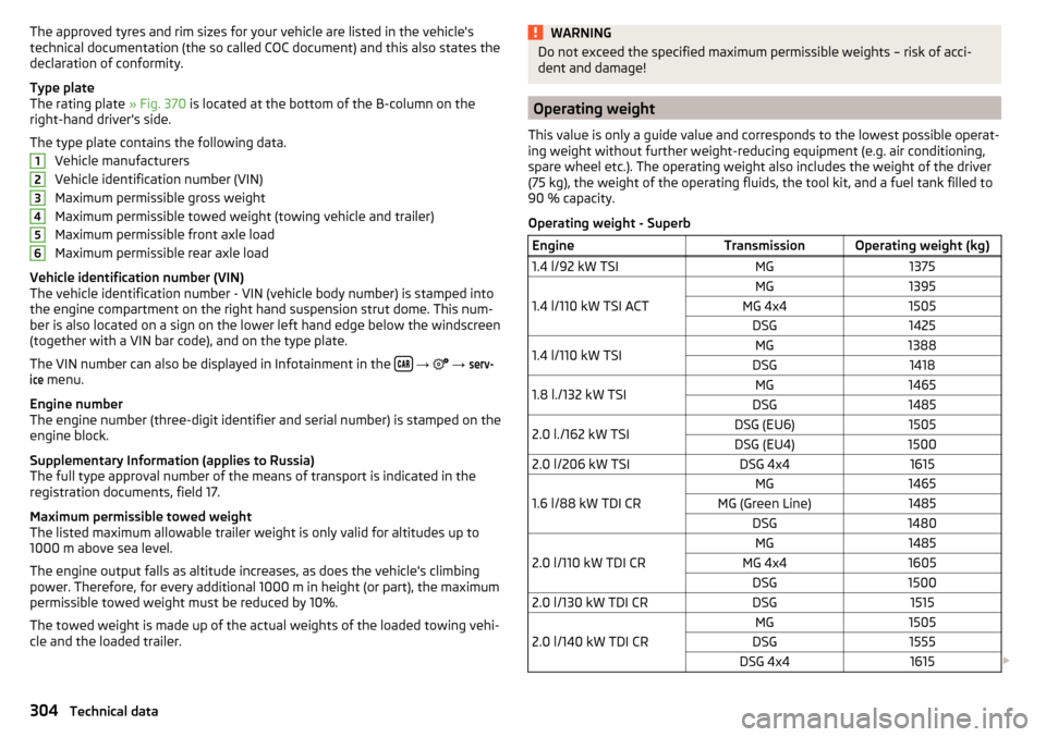
Operating weight
This value is only a guide value and corresponds to the lowest possible operat-
ing weight without further weight-reducing equipment (e.g. air conditioning,
spare wheel etc.). The operating weight also includes the weight of the driver
(75 kg), the weight of the operating fluids, the tool kit, and a fuel tank filled to
90 % capacity.
Operating weight - Superb
EngineTransmissionOperating weight (kg)1.4 l/92 kW TSIMG1375
1.4 l/110 kW TSI ACT
MG1395MG 4x41505DSG14251.4 l/110 kW TSIMG1388DSG14181.8 l./132 kW TSIMG1465DSG14852.0 l./162 kW TSIDSG (EU6)1505DSG (EU4)15002.0 l/206 kW TSIDSG 4x41615
1.6 l/88 kW TDI CR
MG1465MG (Green Line)1485DSG1480
2.0 l/110 kW TDI CR
MG1485MG 4x41605DSG15002.0 l/130 kW TDI CRDSG1515
2.0 l/140 kW TDI CR
MG1505DSG1555DSG 4x41615 304Technical data
Page 307 of 336
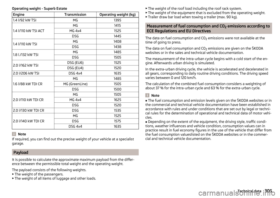
Operating weight - Superb EstateEngineTransmissionOperating weight (kg)1.4 l/92 kW TSIMG1395
1.4 l/110 kW TSI ACT
MG1415MG 4x41525DSG14451.4 l/110 kW TSIMG1408DSG14381.8 l./132 kW TSIMG1485DSG15052.0 l/162 kW TSIDSG (EU6)1525DSG (EU4)15202.0 l/206 kW TSIDSG 4x41635
1.6 l/88 kW TDI CR
MG1485MG (GreenLine)1505DSG1500
2.0 l/110 kW TDI CR
MG1505MG 4x41625DSG15202.0 l/130 kW TDI CRDSG1535
2.0 l/140 kW TDI CR
MG1525DSG1575DSG 4x41635
Note
If required, you can find out the precise weight of your vehicle at a specialist
garage.
Payload
It is possible to calculate the approximate maximum payload from the differ-
ence between the permissible total weight and the operating weight.
The payload consists of the following weights.
▶ The weight of the passengers.
▶ The weight of all items of luggage and other loads.
▶
The weight of the roof load including the roof rack system.
▶ The weight of the equipment that is excluded from the operating weight.
▶ Trailer draw bar load when towing a trailer (max. 90 kg).
Measurement of fuel consumption and CO
2 emissions according to
ECE Regulations and EU Directives
The data on fuel consumption and CO 2 emissions were not available at the
time of going to press.
The data on fuel consumption and CO 2 emissions are given on the ŠKODA
websites or in the sales and technical vehicle documentation.
The measurement of the intra-urban cycle begins with a cold start of the en-
gine. Afterwards urban driving is simulated.
In the extra-urban driving cycle, the vehicle is accelerated and decelerated in
all gears, corresponding to daily routine driving conditions. The driving speed
varies between 0 and 120 km/h.
The calculation of the combined fuel consumption considers a weighting of
about 37 % for the intra-urban cycle and 63 % for the extra-urban cycle.
Note
■ The fuel consumption and emission levels given on the ŠKODA websites or in
the commercial and technical vehicle documentation have been established in
accordance with rules and under conditions that are set out by legal or techni-
cal rules for the determination of operational and technical data of motor vehi-
cles.■
Depending on the extent of the equipment, the driving style, traffic condi-
tions, weather influences and vehicle condition, consumption values can in
practice result in fuel economy figures in the use of the vehicle that differ from
the fuel consumption valueslisted on the ŠKODA websites or in the commer-
cial and technical vehicle documentation.
305Technical data