ECU SKODA YETI 2011 1.G / 5L Owner's Guide
[x] Cancel search | Manufacturer: SKODA, Model Year: 2011, Model line: YETI, Model: SKODA YETI 2011 1.G / 5LPages: 252, PDF Size: 3.61 MB
Page 191 of 252
Inspecting and Replenishing
Engine compartment
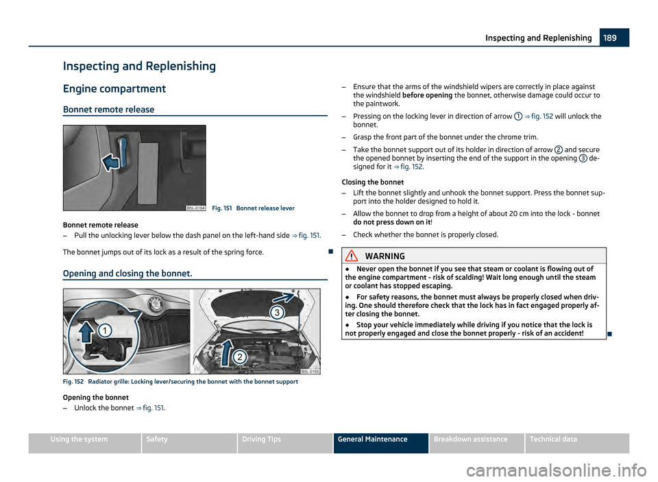
Bonnet remote release Fig. 151 Bonnet release lever
Bonnet remote release
β Pull the unlocking lever below the dash panel on the left-hand side β βfig. 151.
The bonnet jumps out of its lock as a result of the spring force. ο
Opening and closing the bonnet. Fig. 152 Radiator grille: Locking lever/securing the bonnet with the bonnet support
Opening the bonnet
β
Unlock the bonnet β
βfig. 151. β
Ensure that the arms of the windshield wipers are correctly in place against
the windshield before opening the bonnet, otherwise damage could occur to
the paintwork.
β Pressing on the locking lever in direction of arrow 1 β
β
fig. 152 will unlock the
bonnet.
β Grasp the front part of the bonnet under the chrome trim.
β Take the bonnet support out of its holder in direction of arrow 2 and secure
the opened bonnet by inserting the end of the support in the opening 3 de-
signed for it ββfig. 152.
Closing the bonnet
β Lift the bonnet slightly and unhook the bonnet support. Press the bonnet sup-
port into the holder designed to hold it.
β Allow the bonnet to drop from a height of about 20 cm into the lock - bonnet
do not press down on it!
β Check whether the bonnet is properly closed. WARNING
β Never open the bonnet if you see that steam or coolant is flowing out of
the engine compartment - risk of scalding! Wait long enough until the steam
or coolant has stopped escaping.
β For safety reasons, the bonnet must always be properly closed when driv-
ing. One should therefore check that the lock has in fact engaged properly af-
ter closing the bonnet.
β Stop your vehicle immediately while driving if you notice that the lock is
not properly engaged and close the bonnet properly - risk of an accident! ο189
Inspecting and Replenishing Using the system Safety Driving Tips General Maintenance Breakdown assistance Technical data
Page 192 of 252
Working in the engine compartment
Particular care is required when carrying out any work in the en-
gine compartment!
There is a risk of injuries, scalding, accidents and fire when working in the en-
gine compartment, e.g. inspecting and replenishing oil and other fluids. For this
reason, it is essential to comply with the warning instructions stated below and
with the general applicable rules of safety. The engine compartment of your car
is a hazardous area β
β .
WARNING
β Never open the bonnet if you see that steam or coolant is flowing out of
the engine compartment - risk of scalding! Wait long enough until the steam
or coolant has stopped escaping.
β Switch off the engine and pull out the ignition key.
β Apply the handbrake firmly.
β If your vehicle is fitted with a manual gearbox, move the gearshift lever in-
to Neutral, or if it is fitted with automatic gearbox, move the selector lever in-
to position
P.
β Allow the engine to cool down.
β Keep children clear of the engine compartment.
β Do not touch any hot engine parts - risk of burns!
β Never spill oil and other fluids over the hot engine. Such fluids (e.g. the an-
tifreeze contained in the coolant) may ignite!
β Avoid short circuits in the electrical system - particularly on the battery.
β Never place your hand into the radiator fan as long as the engine is still
warm. The fan might suddenly start running!
β Never open the cap of the coolant expansion reservoir so long as the en-
gine is still warm. The cooling system is pressurized!
β Cover over the cap of the reservoir with a large cloth when opening it as
protection for your face, hands and arms from hot steam or hot coolant.
β Do not let objects, such as e.g cleaning cloth or tools lie in the engine com-
partment. WARNING (Continued)
β If you wish to work under the vehicle, you must secure the vehicle from
rolling away and support it with suitable supporting blocks: the car jack is not
sufficient for this - risk of injury!
β In cases where it be necessary to carry out inspection work when the en-
gine is running there is an additional risk from rotating parts (e.g. the V-ribbed
belt, alternator, radiator fan) and from the high-voltage ignition system.
Please observe in addition the following:
βNever touch the electrical cables of the ignition system.
β Absolutely avoid any jewellery, loose items of clothing or long hair from
getting into the rotating parts of the engine - Hazard! Therefore remove
any jewellery beforehand, tie up your hair and wear tight fitting clothing.
β Please also comply with the warning instructions stated below when car-
rying out any essential work on the fuel system or on the electrical system:
βAlways separate the car battery from the electrical system.
β Do not smoke.
β Never carry out any work close to naked flames.
β Always keep a working fire extinguisher at hand. CAUTION
When replenishing fluids in the engine, always ensure that the fluids are on no ac-
count mixed up. This may result in major operating problems and also vehicle
damage! ο190
Inspecting and Replenishing
Page 199 of 252
β
Do not place the battery in direct daylight in order to protect the battery hous-
ing from the effects of ultra-violet light.
β If the vehicle has not been driven for more than 3 to 4 weeks, the battery will
discharge This is because certain electrical components consume electricity (e. g.
control units) also in idle state. You can prevent the discharging of the battery by
disconnecting the negative terminal or charging the battery constantly with a very
low charging current. For the sake of the environment
A removed battery is a special type of waste which is harmful to the environment
- contact your specialist garage regarding disposing of the battery. Note
β Please also refer to the guidelines ββpage 198
, also after connecting the bat-
tery.
β You should replace batteries older than 5 years. ο
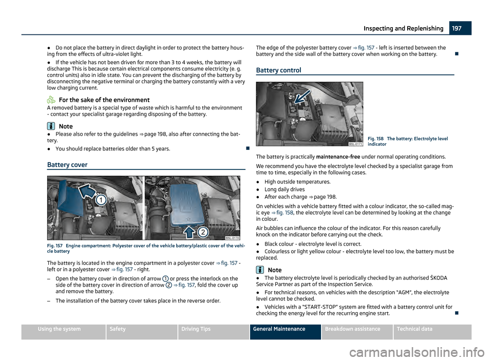
Battery cover Fig. 157 Engine compartment: Polyester cover of the vehicle battery/plastic cover of the vehi-
cle battery
The battery is located in the engine compartment in a polyester cover ββfig. 157 -
left or in a polyester cover ββfig. 157 - right.
β Open the battery cover in direction of arrow 1 or press the interlock on the
side of the battery cover in direction of arrow 2
β
βfig. 157, fold the cover up
and remove the battery.
β The installation of the battery cover takes place in the reverse order. The edge of the polyester battery cover
β
βfig. 157 - left is inserted between the
battery and the side wall of the battery cover when working on the battery. ο
Battery control Fig. 158 The battery: Electrolyte level
indicator
The battery is practically maintenance-free under normal operating conditions.
We recommend you have the electrolyte level checked by a specialist garage from
time to time, especially in the following cases.
β High outside temperatures.
β Long daily drives
β After each charge β
βpage 198.
On vehicles with a vehicle battery fitted with a colour indicator, the so-called mag-
ic eye ββfig. 158 , the electrolyte level can be determined by looking at the change
in colour.
Air bubbles can influence the colour of the indicator. For this reason carefully
knock on the indicator before carrying out the check.
β Black colour - electrolyte level is correct.
β Colourless or light yellow colour - electrolyte level too low, the battery must be
replaced. Note
β The battery electrolyte level is periodically checked by an authorised
Ε KODA
Service Partner as part of the Inspection Service.
β For technical reasons, on vehicles with the description βAGMβ, the electrolyte
level cannot be checked.
β Vehicles with a βSTART-STOPβ system are fitted with a battery control unit for
checking the energy level for the recurring engine start. ο 197
Inspecting and Replenishing Using the system Safety Driving Tips General Maintenance Breakdown assistance Technical data
Page 201 of 252
Replacing the battery
When replacing a battery, the new new battery must have the same capacity,
voltage (12
V), amperage and be the same size. Suitable types of vehicle battery
are available from an authorised Ε KODA Service Partner.
We recommend you have a battery change carried out by an authorised Ε KODA
Service Partner, who will properly install the new battery and dispose of the origi-
nal one. CAUTION
Vehicles with a βSTART-STOPβ system are fitted with a special battery type which
allows the battery control unit to check the energy level for recurring engine start.
This battery must only be replaced by a battery of the same type. For the sake of the environment
Batteries contain poisonous substances such as sulphuric acid and lead. For this
reason, it must be disposed of properly. Under no circumstances must it be dis-
posed of in the communal rubbish. ο
Automatic consumer shut-off Under heavy load on the vehicle battery, the vehicle electrical system manage-
ment automatically takes various measures to avoid draining the vehicle battery.
β
The idling speed is raised to allow the generator to deliver more electricity to
the electrical system.
β If necessary, some electrical consumers are limited in their performance or are
temporarily switched off completely. Note
Despite such intervention by the vehicle electric system management, the vehicle
battery may be drained. For example, when the ignition is switched on a long time
with the engine turned off or the side or parking lights are turned on during lon-
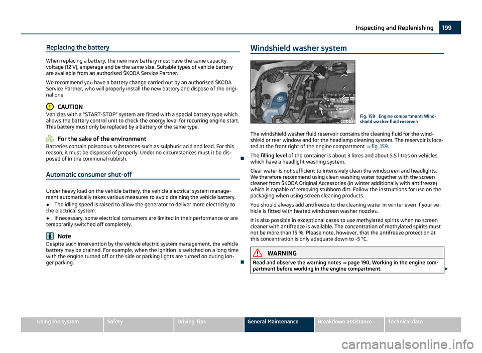
ger parking. οWindshield washer system Fig. 159 Engine compartment: Wind-
shield washer fluid reservoir
The windshield washer fluid reservoir contains the cleaning fluid for the wind-
shield or rear window and for the headlamp cleaning system. The reservoir is loca-
ted at the front right of the engine compartment ββfig. 159 .
The filling level of the container is about 3 litres and about 5.5 litres on vehicles
which have a headlight washing system.
Clear water is not sufficient to intensively clean the windscreen and headlights.
We therefore recommend using clean washing water together with the screen
cleaner from
Ε KODA Original Accessories (in winter additionally with antifreeze)
which is capable of removing stubborn dirt. Follow the instructions for use on the
packaging when using screen cleaning products.
You should always add antifreeze to the cleaning water in winter even if your ve-
hicle is fitted with heated windscreen washer nozzles.
It is also possible in exceptional cases to use methylated spirits when no screen
cleaner with antifreeze is available. The concentration of methylated spirits must
not be more than 15 %. Please note, however, that the antifreeze protection at
this concentration is only adequate down to -5 Β°C. WARNING
Read and observe the warning notes ββpage 190
, Working in the engine com-
partment before working in the engine compartment. Β£ 199
Inspecting and Replenishing Using the system Safety Driving Tips General Maintenance Breakdown assistance Technical data
Page 211 of 252
The vehicle tool kit and the lifting jack, on which a sign is affixed, are stowed in a
box in the luggage compartment
β
βfig. 164; there is also space here for the de-
tachable ball head of the towing device. The box is secured with a strap. The
placement of the vehicle tool kit can vary depending on the vehicle equipment.
The vehicle tool kit contains the following parts (depending on equipment fitted):
β Tyre repair kit
β Wire clamps for removing the full wheel trims,
β Wheel wrench,
β Towing eye,
β Adapter for the wheel bolts lock,
β Replacement lamp,
β Torx screwdriver.
Before placing the lifting jack back in its storage area, screw in the arm of the lift-
ing jack fully. WARNING
β The factory-supplied lifting jack is only intended for your model of vehicle.
On no account attempt to lift a heavier vehicle or other loads - risk of injury!
β Ensure that the vehicle tool kit is safely attached in the luggage compart-
ment. Note
Ensure that the box is always secured with the strap. ο
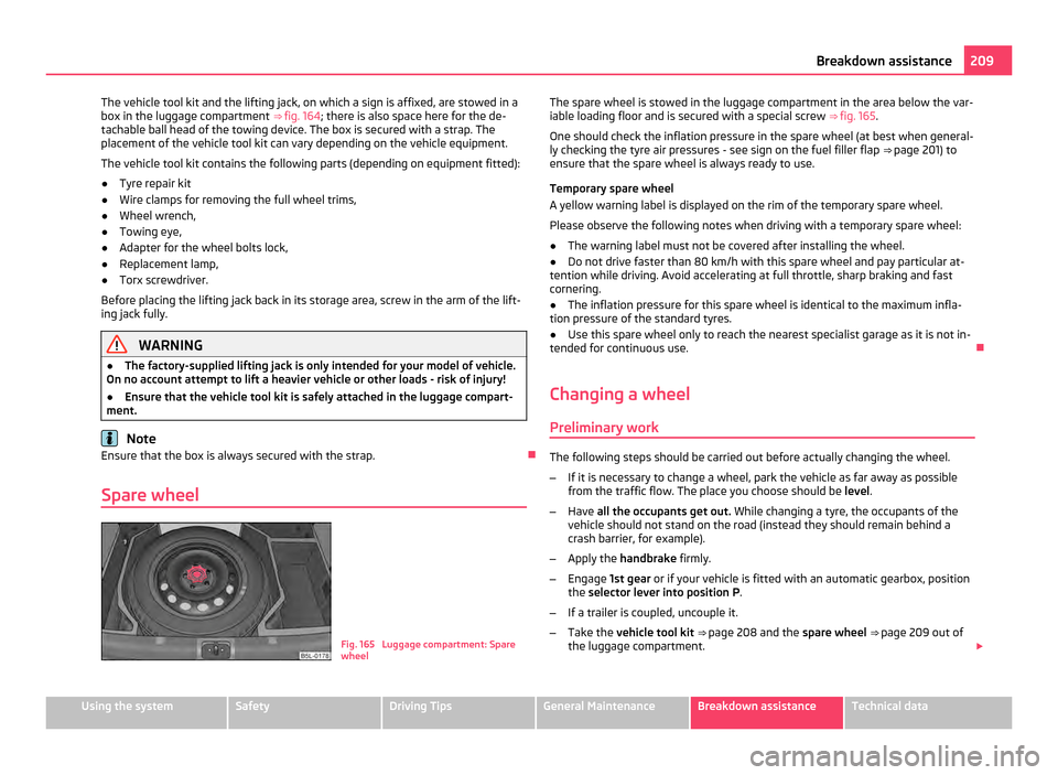
Spare wheel Fig. 165 Luggage compartment: Spare
wheelThe spare wheel is stowed in the luggage compartment in the area below the var-
iable loading floor and is secured with a special screw
ββfig. 165.
One should check the inflation pressure in the spare wheel (at best when general-
ly checking the tyre air pressures - see sign on the fuel filler flap ββpage 201) to
ensure that the spare wheel is always ready to use.
Temporary spare wheel
A yellow warning label is displayed on the rim of the temporary spare wheel.
Please observe the following notes when driving with a temporary spare wheel:
β The warning label must not be covered after installing the wheel.
β Do not drive faster than 80 km/h with this spare wheel and pay particular at-
tention while driving. Avoid accelerating at full throttle, sharp braking and fast
cornering.
β The inflation pressure for this spare wheel is identical to the maximum infla-
tion pressure of the standard tyres.
β Use this spare wheel only to reach the nearest specialist garage as it is not in-
tended for continuous use. ο
Changing a wheel Preliminary work The following steps should be carried out before actually changing the wheel.
β If it is necessary to change a wheel, park the vehicle as far away as possible
from the traffic flow. The place you choose should be level.
β Have all the occupants get out. While changing a tyre, the occupants of the
vehicle should not stand on the road (instead they should remain behind a
crash barrier, for example).
β Apply the handbrake firmly.
β Engage 1st gear or if your vehicle is fitted with an automatic gearbox, position
the selector lever into position P .
β If a trailer is coupled, uncouple it.
β Take the vehicle tool kit ββ page 208
and the spare wheel ββpage 209 out of
the luggage compartment. Β£ 209
Breakdown assistance Using the system Safety Driving Tips General Maintenance Breakdown assistance Technical data
Page 212 of 252
WARNING
β If you find yourself in flowing traffic switch on the hazard warning lights
system and place the warning triangle on the side of the road at the prescri-
bed distance from your vehicle. Comply with the national legal regulations. In
this way you are protecting not only yourself but also other road users.
β Never start the engine with the vehicle sitting on the raised jack - danger
of suffering injury. CAUTION
If you have to change a wheel on a slope first block the opposite wheel with a
stone or similar object in order to secure the vehicle from unexpectedly rolling
away. Note
Comply with the national legal regulations. ο
Changing a wheel Always change a wheel on a level surface as far as possible.
β
Take off the full wheel trim ββpage 210 or the wheel trim cap ββpage 211 or
the caps ββpage 211.
β In the case of light alloy wheels remove the wheel trim cap β
βpage 211.
β First of all slacken the safety wheel bolt and afterwards the other wheel bolts
ββ page 211.
β Jack up the vehicle until the wheel to be changed is clear of the ground
ββpage 212.
β Unscrew the wheel bolts and place them on a clean surface (cloth, paper etc.).
β Take off the wheel.
β Fit on the spare wheel and tighten the wheel bolts slightly.
β Lower the car.
β Tighten the wheel bolts firmly, alternately and diagonally using the wheel
wrench (crosswise) and lastly the wheel safety bolt β
βpage 211.
β Mount the full wheel trim/wheel trim cap or the caps. Note
β All bolts must be clean and must turn easily.
β You must never grease or oil the wheel bolts!
β When fitting on unidirectional tyres, ensure that the tyres rotate in the correct
direction ββpage 201
. ο
Subsequent steps After changing the wheel, you must perform the following steps.
β
Stow and attach the replaced wheel in the spare wheel well using a special
screw ββfig. 165 .
β Stow the vehicle tool kit in the space provided.
β Check the tyre pressure on the spare wheel just mounted as soon as possible.
β Have the tightening torque of the wheel bolts checked with a torque wrench
as soon as possible. Steel and light alloy wheels must be tightened to a tight-
ening torque of 120
Nm.
β Change the damaged wheel or consult a specialist garage about possibilities
for getting repairs done. WARNING
It is necessary to observe the guidelines given on β
βpage 203 if the vehicle is
subsequently fitted with tyres which are different to those it was fitted with
at the works. Note
β If you find, when changing the wheel, that the wheel bolts are corroded and
difficult to turn, the bolts must be replaced before checking the tightening torque.
β Drive cautiously and only at a moderate speed to a workshop where the tight-
ening torque can be checked. ο
Full wheel trim Pulling off
β
Hook the clamp found in the vehicle tool kit into the reinforced edge of the full
wheel trim. Β£210
Breakdown assistance
Page 215 of 252
WARNING (Continued)
β Secure the base plate of the lifting jack with suitable means to prevent
possible moving. A soft and slippery ground under the base plate may move
the lifting jack, causing the vehicle to fall down. It is therefore always neces-
sary to place the lifting jack on a solid surface or use a wide and stable base.
Use a non-slip base (e.g. a rubber foot mat) if the
surface is smooth, such as
cobbled stones, a tiled floor, etc.
β Attach the lifting jack only at the attachment points provided for this pur-
pose. ο
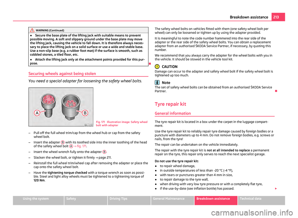
Securing wheels against being stolen You need a special adapter for loosening the safety wheel bolts.
Fig. 171 Illustration image: Safety wheel
bolt with adapter
β Pull off the full wheel trim/cap from the wheel hub or cap from the safety
wheel bolt.
β Insert the adapter B with its toothed side into the inner toothing of the head
of the safety wheel bolt A
β
βfig. 171 .
β Insert the wheel wrench fully onto the adapter B .
β Slacken the wheel bolt, or tighten it firmly ββpage 211.
β Reinstall the full wheel trim/wheel cap after removing the adapter or place the
cap onto the safety wheel bolt.
β Have the tightening torque checked with a torque wrench as soon as possi-
ble. Steel and light alloy wheels must be tightened to a tightening torque of
120
Nm. The safety wheel bolts on vehicles fitted with them (one safety wheel bolt per
wheel) can only be loosened or tighten up by using the adapter provided.
It is meaningful to note the code number hammered into the rear side of the
adapter or the rear side of the safety wheel bolts. You can obtain a replacement
adapter from an authorised
Ε KODA Service Partner, if necessary, by quoting this
number.
We recommend that you always carry the adapter for the wheel bolts with you in
the vehicle. It should be stowed in the vehicle tool kit. CAUTION
Damage can occur to the adapter and safety wheel bolt if the safety wheel bolt is
tightened up too much. Note
The set of safety wheel bolts can be obtained from an authorised Ε KODA Service
Partner. ο
Tyre repair kit General information The tyre repair kit is located in a box under the carpet in the luggage compart-
ment.
Use the tyre repair kit to reliably repair tyre damage caused by foreign bodies or a
puncture with diameters up to 4 mm. Do not remove foreign bodies, e.g. screws or
nails, from the tyre!
The repair can be undertaken on the vehicle immediately.
The repair with the tyre repair kit is not at all intended to replace a permanent
repair on the tyre, this repair only serves to reach the next specialist garage.
Do not use the tyre repair kit:
β to repair wheel damage,
β in outside temperatures of less than -20 Β°C (-4 Β°F),
β with tears or punctures greater than 4 mm in size,
β to repair damage to the tyre wall,
β when driving with very low tyre pressure or with a completely flat tyre,
β if the use-by-date (see inflation bottle) has passed. Β£ 213
Breakdown assistance Using the system Safety Driving Tips General Maintenance Breakdown assistance Technical data
Page 227 of 252
Main beam light and low beam light
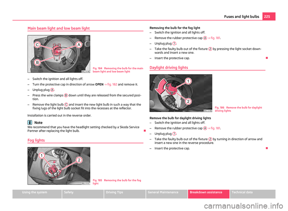
Fig. 184 Removing the bulb for the main
beam light and low beam light
β Switch the ignition and all lights off.
β Turn the protective cap in direction of arrow OPEN β βfig. 182 and remove it.
β Unplug plug A .
β Press the wire clamps B down until they are released from the secured posi-
tion.
β Remove the light bulb C and insert the new light bulb in such a way that the
fixing lugs of the light bulb socket fit into the recesses at the reflector.
Installation is carried out in the reverse order. Note
We recommend that you have the headlight setting checked by a Skoda Service
Partner after replacing the light bulb. ο
Fog lights Fig. 185 Removing the bulb for the fog
light Removing the bulb for the fog light
β
Switch the ignition and all lights off.
β Remove the rubber protective cap A ββfig. 181
.
β Unplug plug 1 .
β Take the faulty bulb out of the fixture 2 by pressing the light socket down-
wards and insert a new one.
β Insert the protective cap. ο
Daylight driving lights Fig. 186 Remove the bulb for daylight
driving lights
Remove the bulb for daylight driving lights
β Switch the ignition and all lights off.
β Remove the rubber protective cap A
ββ fig. 181 .
β Unplug plug 1 .
β Take the faulty bulb out of the fixture 2 by turning in direction of arrow and
insert a new one in the reverse procedure.
β Insert the protective cap. ο 225
Fuses and light bulbs Using the system Safety Driving Tips General Maintenance Breakdown assistance Technical data
Page 228 of 252
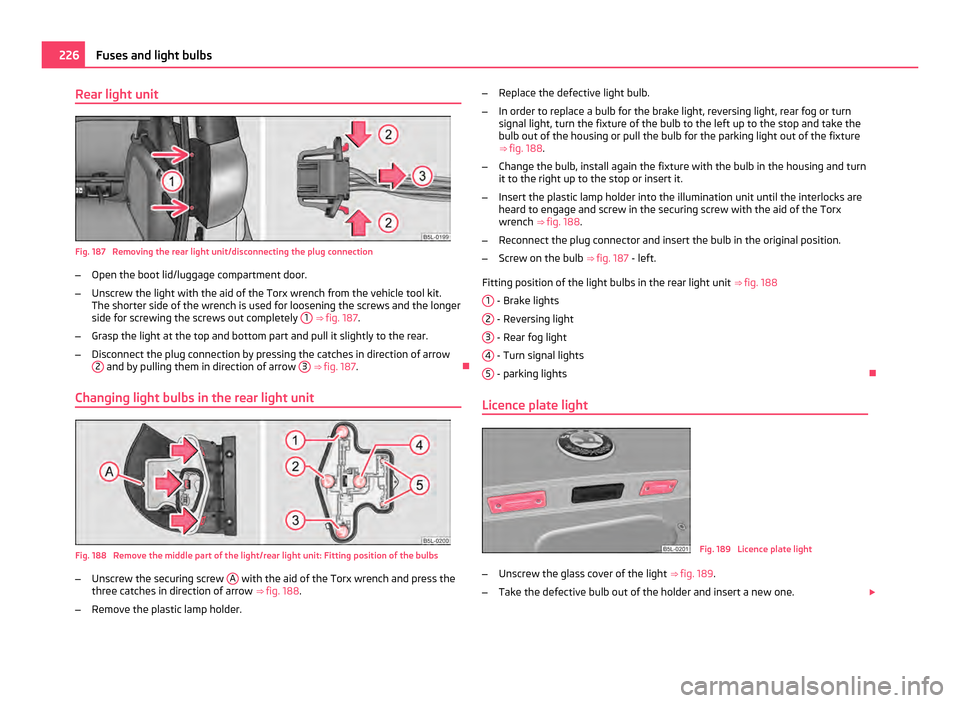
Rear light unit
Fig. 187 Removing the rear light unit/disconnecting the plug connection
β Open the boot lid/luggage compartment door.
β Unscrew the light with the aid of the Torx wrench from the vehicle tool kit.
The shorter side of the wrench is used for loosening the screws and the longer
side for screwing the screws out completely 1
β βfig. 187.
β Grasp the light at the top and bottom part and pull it slightly to the rear.
β Disconnect the plug connection by pressing the catches in direction of arrow
2 and by pulling them in direction of arrow
3
β
βfig. 187. ο
Changing light bulbs in the rear light unit Fig. 188 Remove the middle part of the light/rear light unit: Fitting position of the bulbs
β
Unscrew the securing screw A with the aid of the Torx wrench and press the
three catches in direction of arrow ββfig. 188 .
β Remove the plastic lamp holder. β
Replace the defective light bulb.
β In order to replace a bulb for the brake light, reversing light, rear fog or turn
signal light, turn the fixture of the bulb to the left up to the stop and take the
bulb out of the housing or pull the bulb for the parking light out of the fixture
ββfig. 188 .
β Change the bulb, install again the fixture with the bulb in the housing and turn
it to the right up to the stop or insert it.
β Insert the plastic lamp holder into the illumination unit until the interlocks are
heard to engage and screw in the securing screw with the aid of the Torx
wrench β
βfig. 188 .
β Reconnect the plug connector and insert the bulb in the original position.
β Screw on the bulb β
βfig. 187 - left.
Fitting position of the light bulbs in the rear light unit ββfig. 188
1 - Brake lights
2 - Reversing light
3 - Rear fog light
4 - Turn signal lights
5 - parking lights
ο
Licence plate light Fig. 189 Licence plate light
β Unscrew the glass cover of the light β
βfig. 189 .
β Take the defective bulb out of the holder and insert a new one. Β£226
Fuses and light bulbs
Page 245 of 252
Operation in winter
Battery . . . . . . . . . . . . . . . . . . . . . . . . . . . . . . . . . . . . . 198
Biodiesel . . . . . . . . . . . . . . . . . . . . . . . . . . . . . . . . . . . 187
De-icing windows . . . . . . . . . . . . . . . . . . . . . . . . . . . 182
Outside temperature . . . . . . . . . . . . . . . . . . . . . . . . . . . 15
Overview of the engine compartment . . . . . . . . . . . 191
P Paint . . . . . . . . . . . . . . . . . . . . . . . . . . . . . . . . . . . . . . . . 182
Paint damage . . . . . . . . . . . . . . . . . . . . . . . . . . . . . . . . 182
Panoramic sliding roof . . . . . . . . . . . . . . . . . . . . . . . . . 42
Park Assist . . . . . . . . . . . . . . . . . . . . . . . . . . . . . . . . . . 105
Parking . . . . . . . . . . . . . . . . . . . . . . . . . . . . . . . . . . . . . 103
Parking aid Front and rear . . . . . . . . . . . . . . . . . . . . . . . . . . . . . . 104
rear . . . . . . . . . . . . . . . . . . . . . . . . . . . . . . . . . . . . . . . . 103
Parking light . . . . . . . . . . . . . . . . . . . . . . . . . . . . . . . . . 47
Parking the vehicle . . . . . . . . . . . . . . . . . . . . . . . . . . 103
Passive Safety . . . . . . . . . . . . . . . . . . . . . . . . . . . . . . . 128
Payload . . . . . . . . . . . . . . . . . . . . . . . . . . . . . . . . . . . . . 228
Pedals . . . . . . . . . . . . . . . . . . . . . . . . . . . . . . . . . . . 70, 102
Petrol . . . . . . . . . . . . . . . . . . . . . . . . . . . . . . . . . . . . . . . 186
Petrol engines Starting the engine . . . . . . . . . . . . . . . . . . . . . . . . . 101
Polishing . . . . . . . . . . . . . . . . . . . . . . . . . . . . . . . . . . . . 182
Power steering . . . . . . . . . . . . . . . . . . . . . . . . . . . . . . 158 Warning light . . . . . . . . . . . . . . . . . . . . . . . . . . . . . . . . 25
Power windows . . . . . . . . . . . . . . . . . . . . . . . . . . . . . . . 39 Button in the driver's door . . . . . . . . . . . . . . . . . . . 39
Button in the front passenger door and in therear doors . . . . . . . . . . . . . . . . . . . . . . . . . . . . . . . . . 40
Operational faults . . . . . . . . . . . . . . . . . . . . . . . . . . . . 42
with central locking system . . . . . . . . . . . . . . . . . . . 41
R Radiator fan . . . . . . . . . . . . . . . . . . . . . . . . . . . . . . . . . 195 Rear-view mirror
Exterior mirror . . . . . . . . . . . . . . . . . . . . . . . . . . . . . . 58
Interior mirror . . . . . . . . . . . . . . . . . . . . . . . . . . . . . . . 58
Rear armrest . . . . . . . . . . . . . . . . . . . . . . . . . . . . . . . . . 69
Rear fog light . . . . . . . . . . . . . . . . . . . . . . . . . . . . . . . . . 49 Warning light . . . . . . . . . . . . . . . . . . . . . . . . . . . . . . . . 24
Rear interior lighting . . . . . . . . . . . . . . . . . . . . . . . . . . 52
Rear seats . . . . . . . . . . . . . . . . . . . . . . . . . . . . . . . . . . . . 66
Rear window Heater . . . . . . . . . . . . . . . . . . . . . . . . . . . . . . . . . . . . . . 53
Rear window heater . . . . . . . . . . . . . . . . . . . . . . . . . . . 53
Recharge battery . . . . . . . . . . . . . . . . . . . . . . . . . . . . 198
Recommendation for changing gears . . . . . . . . . . . 14
Refuelling . . . . . . . . . . . . . . . . . . . . . . . . . . . . . . . . . . . 187
Remote control . . . . . . . . . . . . . . . . . . . . . . . . . . . . . . . 37 Synchronisation . . . . . . . . . . . . . . . . . . . . . . . . . . . . . 38
Removing seats . . . . . . . . . . . . . . . . . . . . . . . . . . . . . . . 67
Replacement of parts . . . . . . . . . . . . . . . . . . . . . . . . 207
Replacing fuses . . . . . . . . . . . . . . . . . . . . . . . . . . . . . . 220
Replacing the wiper blades . . . . . . . . . . . . . . . . . . . . 57
Roof aerial . . . . . . . . . . . . . . . . . . . . . . . . . . . . . . . . . . . 181
Roof luggage rack system . . . . . . . . . . . . . . . . . . . . . 76
Running in . . . . . . . . . . . . . . . . . . . . . . . . . . . . . . . . . . 162
S
Safe securing . . . . . . . . . . . . . . . . . . . . . . . . . . . . . . . . . 34
Safety . . . . . . . . . . . . . . . . . . . . . . . . . . . . . . . . . . . . . . 128
Safety information Engine compartment . . . . . . . . . . . . . . . . . . . . . . . 190
Safety wheel bolts . . . . . . . . . . . . . . . . . . . . . . . . . . . 213
Saving electrical energy . . . . . . . . . . . . . . . . . . . . . . 163
Seat belt height adjuster Seat belts . . . . . . . . . . . . . . . . . . . . . . . . . . . . . . . . . . 134
Seat belts . . . . . . . . . . . . . . . . . . . . . . . . . . . . . . . . . . . 132 Belt tensioners . . . . . . . . . . . . . . . . . . . . . . . . . . . . . 135
Cleaning . . . . . . . . . . . . . . . . . . . . . . . . . . . . . . . . . . . . 185
fastening . . . . . . . . . . . . . . . . . . . . . . . . . . . . . . . . . . . 134
Safety information . . . . . . . . . . . . . . . . . . . . . . . . . . 133 taking off . . . . . . . . . . . . . . . . . . . . . . . . . . . . . . . . . . . 135
Warning light . . . . . . . . . . . . . . . . . . . . . . . . . . . . . . . 28
Seat belt warning light . . . . . . . . . . . . . . . . . . . . . . . 134
Seat heating . . . . . . . . . . . . . . . . . . . . . . . . . . . . . . . . . . 69
Selector lever . . . . . . . . . . . . . . . . . . . . . . . . . . . . . . . . . 113
Selector lever-emergency unlocking . . . . . . . . . . . . 116
Selector lever lock Warning light . . . . . . . . . . . . . . . . . . . . . . . . . . . . . . . . 27
Selector lever positions . . . . . . . . . . . . . . . . . . . . . . . . 113
Service reminder indicator . . . . . . . . . . . . . . . . . . . . . 12
Setting temperature Heating . . . . . . . . . . . . . . . . . . . . . . . . . . . . . . . . . . . . 88
Setting the clock . . . . . . . . . . . . . . . . . . . . . . . . . . . . . . 13
Shifting . . . . . . . . . . . . . . . . . . . . . . . . . . . . . . . . . . . . . 102
Side airbag . . . . . . . . . . . . . . . . . . . . . . . . . . . . . . . . . . . 141
Side lights . . . . . . . . . . . . . . . . . . . . . . . . . . . . . . . . . . . . 45
Snow chains . . . . . . . . . . . . . . . . . . . . . . . . . . . . . . . . . 205
Spare wheel . . . . . . . . . . . . . . . . . . . . . . . . . . . . . . . . . 209
Speedometer . . . . . . . . . . . . . . . . . . . . . . . . . . . . . . . . . . 11
Stabilisation system . . . . . . . . . . . . . . . . . . . . . . . . . . 153
START-STOP . . . . . . . . . . . . . . . . . . . . . . . . . . . . . . . . . 110
Starting the engine . . . . . . . . . . . . . . . . . . . . . . . . . . 100 after fuel tank has run empty . . . . . . . . . . . . . . . . 101
Diesel engines . . . . . . . . . . . . . . . . . . . . . . . . . . . . . . 101
Petrol engines . . . . . . . . . . . . . . . . . . . . . . . . . . . . . . 101
Static separation net . . . . . . . . . . . . . . . . . . . . . . . . . . 73
Steering active driver-steering recommendation . . . . . . . 155
Steering force assistance . . . . . . . . . . . . . . . . . . . . . 158
Storage compartment Lighting . . . . . . . . . . . . . . . . . . . . . . . . . . . . . . . . . . . . . 52
Storage compartments . . . . . . . . . . . . . . . . . . . . . . . . 80
Storage facilities . . . . . . . . . . . . . . . . . . . . . . . . . . . . . . 80
Sun . . . . . . . . . . . . . . . . . . . . . . . . . . . . . . . . . . . . . . . . . . 54
Switching off the engine . . . . . . . . . . . . . . . . . . . . . . 101
Switch off Anti-spin regulation (ASR) Warning light . . . . . . . . . . . . . . . . . . . . . . . . . . . . . . . . 27 243
Index Using the system Safety Driving Tips General Maintenance Breakdown assistance Technical data