technical data SKODA YETI 2011 1.G / 5L Service Manual
[x] Cancel search | Manufacturer: SKODA, Model Year: 2011, Model line: YETI, Model: SKODA YETI 2011 1.G / 5LPages: 252, PDF Size: 3.61 MB
Page 81 of 252
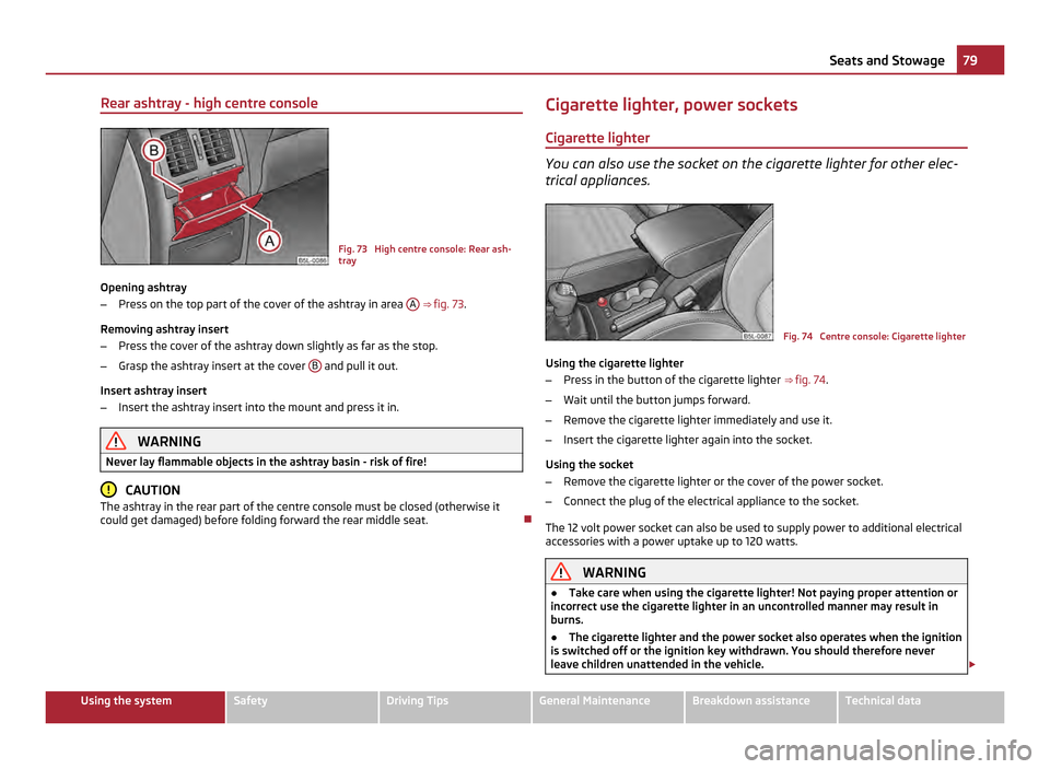
Rear ashtray - high centre console
Fig. 73 High centre console: Rear ash-
tray
Opening ashtray
– Press on the top part of the cover of the ashtray in area A
⇒ fig. 73.
Removing ashtray insert
– Press the cover of the ashtray down slightly as far as the stop.
– Grasp the ashtray insert at the cover B and pull it out.
Insert ashtray insert
– Insert the ashtray insert into the mount and press it in. WARNING
Never lay flammable objects in the ashtray basin - risk of fire! CAUTION
The ashtray in the rear part of the centre console must be closed (otherwise it
could get damaged) before folding forward the rear middle seat. Cigarette lighter, power sockets
Cigarette lighter You can also use the socket on the cigarette lighter for other elec-
trical appliances.
Fig. 74 Centre console: Cigarette lighter
Using the cigarette lighter
– Press in the button of the cigarette lighter ⇒ fig. 74.
– Wait until the button jumps forward.
– Remove the cigarette lighter immediately and use it.
– Insert the cigarette lighter again into the socket.
Using the socket
– Remove the cigarette lighter or the cover of the power socket.
– Connect the plug of the electrical appliance to the socket.
The 12 volt power socket can also be used to supply power to additional electrical
accessories with a power uptake up to 120 watts. WARNING
● Take care when using the cigarette lighter! Not paying proper attention or
incorrect use the cigarette lighter in an uncontrolled manner may result in
burns.
● The cigarette lighter and the power socket also operates when the ignition
is switched off or the ignition key withdrawn. You should therefore never
leave children unattended in the vehicle. £ 79
Seats and Stowage Using the system Safety Driving Tips General Maintenance Breakdown assistance Technical data
Page 83 of 252
Opening and closing the storage compartment on the front passenger side
–
Press the button ⇒ fig. 76 - the lid folds down.
– Raise the lid and press it until the catch is heard to engage.
In the storage compartment are pin holders. WARNING
The storage compartment must always be closed when driving for safety rea-
sons.
Cooling of storage compartment on front passenger
side Fig. 77 Storage compartment: Using
cooling system
– You can switch on the cooling system by pulling the lever in direction of arrow
⇒ fig. 77.
– Switch off the cooling system by inserting the lever.
Opening the air supply when the air conditioning system is switched on allows
cooled air to flow into the storage compartment.
Opening the air inlet when the air conditioning system is on causes fresh or interi-
or air to flow into the storage compartment.
We recommend that you switch off the cooling if it is operating in the heating
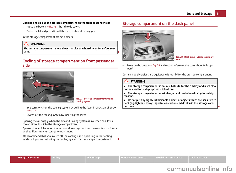
mode or if you are not using the cooling system for the storage compartment. Storage compartment on the dash panel
Fig. 78 Dash panel: Storage compart-
ment
– Press on the button ⇒ fig. 78 in direction of arrow, the cover then folds up-
wards.
Certain model versions are equipped without lid for the storage compartment. WARNING
● The storage compartment is not a substitute for the ashtray and must also
not be used for such purposes - risk of fire!
● The storage compartment must always be closed when driving for safety
reasons.
● Do not put any highly inflammable objects or objects which are sensitive to
heat (e.g. lighters, sprays, spectacles, carbonated drinks) in the storage com-
partment. 81
Seats and Stowage Using the system Safety Driving Tips General Maintenance Breakdown assistance Technical data
Page 85 of 252
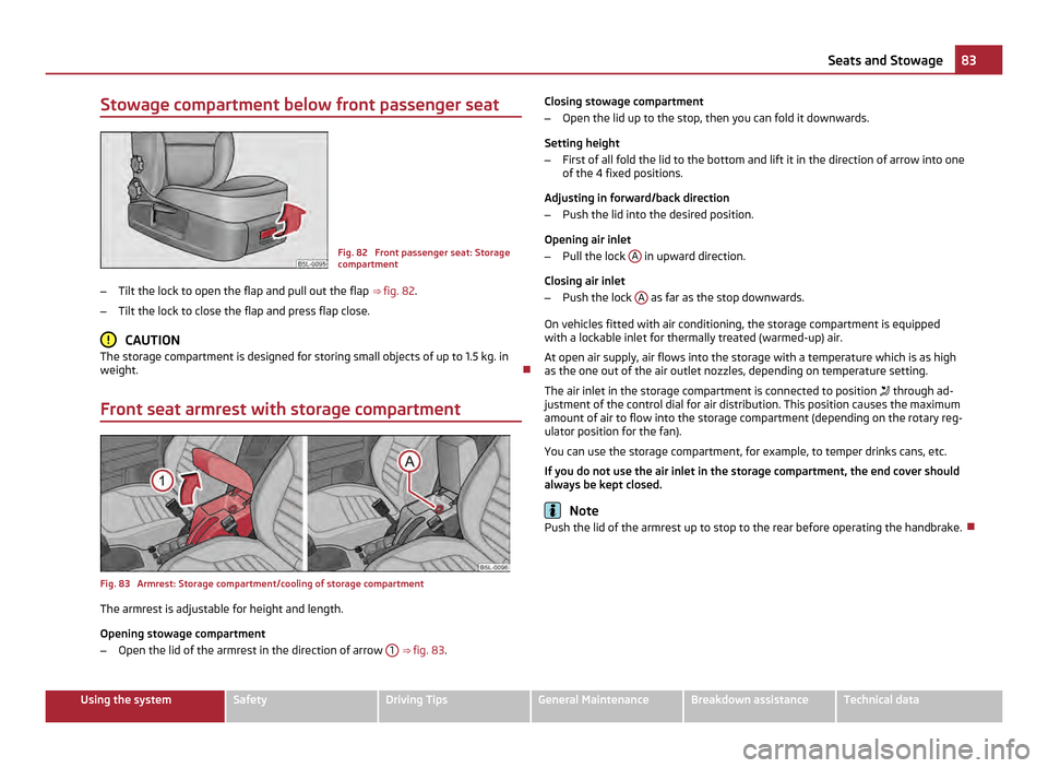
Stowage compartment below front passenger seat
Fig. 82 Front passenger seat: Storage
compartment
– Tilt the lock to open the flap and pull out the flap ⇒ fig. 82 .
– Tilt the lock to close the flap and press flap close. CAUTION
The storage compartment is designed for storing small objects of up to 1.5 kg. in
weight.
Front seat armrest with storage compartment Fig. 83 Armrest: Storage compartment/cooling of storage compartment
The armrest is adjustable for height and length.
Opening stowage compartment
–
Open the lid of the armrest in the direction of arrow 1
⇒ fig. 83 . Closing stowage compartment
– Open the lid up to the stop, then you can fold it downwards.
Setting height
– First of all fold the lid to the bottom and lift it in the direction of arrow into one
of the 4 fixed positions.
Adjusting in forward/back direction
– Push the lid into the desired position.
Opening air inlet
– Pull the lock A in upward direction.
Closing air inlet
– Push the lock A as far as the stop downwards.
On vehicles fitted with air conditioning, the storage compartment is equipped
with a lockable inlet for thermally treated (warmed-up) air.
At open air supply, air flows into the storage with a temperature which is as high
as the one out of the air outlet nozzles, depending on temperature setting.
The air inlet in the storage compartment is connected to position through ad-
justment of the control dial for air distribution. This position causes the maximum
amount of air to flow into the storage compartment (depending on the rotary reg-
ulator position for the fan).
You can use the storage compartment, for example, to temper drinks cans, etc.
If you do not use the air inlet in the storage compartment, the end cover should
always be kept closed. Note
Push the lid of the armrest up to stop to the rear before operating the handbrake. 83
Seats and Stowage Using the system Safety Driving Tips General Maintenance Breakdown assistance Technical data
Page 87 of 252
Removable through-loading bag
The removable through-loading bag is solely used for transporting
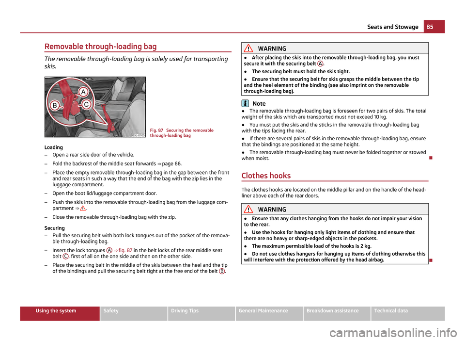
skis. Fig. 87 Securing the removable
through-loading bag
Loading
– Open a rear side door of the vehicle.
– Fold the backrest of the middle seat forwards ⇒ page 66.
– Place the empty removable through-loading bag in the gap between the front
and rear seats in such a way that the end of the bag with the zip lies in the
luggage compartment.
– Open the boot lid/luggage compartment door.
– Push the skis into the removable through-loading bag from the luggage com-
partment ⇒ .
– Close the removable through-loading bag with the zip.
Securing
– Pull the securing belt with both lock tongues out of the pocket of the remova-
ble through-loading bag.
– Insert the lock tongues A
⇒ fig. 87 in the belt locks of the rear middle seat
belt C , first of all on the one side and then on the other side.
– Place the securing belt in the middle of the skis between the heel and the tip
of the bindings and pull the securing belt tight at the free end of the belt B . WARNING
● After placing the skis into the removable through-loading bag, you must
secure it with the securing belt A .
● The securing belt must hold the skis tight.
● Ensure that the securing belt for skis grasps the middle between the tip
and the heel element of the binding (see also imprint on the removable
through-loading bag). Note
● The removable through-loading bag is foreseen for two pairs of skis. The total
weight of the skis which are transported must not exceed 10 kg.
● You must put the skis and the sticks in the removable through-loading bag
with the tips facing the rear.
● If there are several pairs of skis in the removable through-loading bag, ensure
that the bindings are positioned at the same height.
● The removable through-loading bag must never be folded together or stowed
when moist.
Clothes hooks The clothes hooks are located on the middle pillar and on the handle of the head-
liner above each of the rear doors.
WARNING
● Ensure that any clothes hanging from the hooks do not impair your vision
to the rear.
● Use the hooks for hanging only light items of clothing and ensure that
there are no heavy or sharp-edged objects in the pockets.
● The maximum permissible load of the hooks is 2 kg.
● Do not use clothes hangers for hanging up items of clothing otherwise this
will interfere with the protection offered by the head airbag. 85
Seats and Stowage Using the system Safety Driving Tips General Maintenance Breakdown assistance Technical data
Page 89 of 252
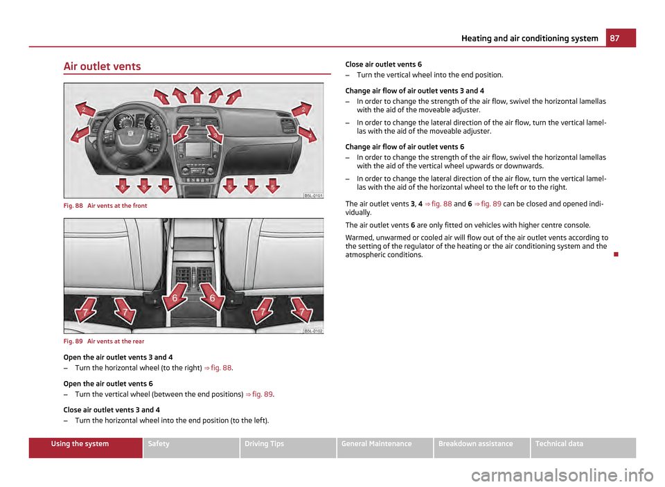
Air outlet vents
Fig. 88 Air vents at the front
Fig. 89 Air vents at the rear
Open the air outlet vents 3 and 4
–
Turn the horizontal wheel (to the right) ⇒ fig. 88 .
Open the air outlet vents 6
– Turn the vertical wheel (between the end positions) ⇒ fig. 89 .
Close air outlet vents 3 and 4
– Turn the horizontal wheel into the end position (to the left). Close air outlet vents 6
–
Turn the vertical wheel into the end position.
Change air flow of air outlet vents 3 and 4
– In order to change the strength of the air flow, swivel the horizontal lamellas
with the aid of the moveable adjuster.
– In order to change the lateral direction of the air flow, turn the vertical lamel-
las with the aid of the moveable adjuster.
Change air flow of air outlet vents 6
– In order to change the strength of the air flow, swivel the horizontal lamellas
with the aid of the vertical wheel upwards or downwards.
– In order to change the lateral direction of the air flow, turn the vertical lamel-
las with the aid of the horizontal wheel to the left or to the right.
The air outlet vents 3, 4 ⇒
fig. 88 and 6 ⇒ fig. 89 can be closed and opened indi-
vidually.
The air outlet vents 6 are only fitted on vehicles with higher centre console.
Warmed, unwarmed or cooled air will flow out of the air outlet vents according to
the setting of the regulator of the heating or the air conditioning system and the
atmospheric conditions. 87
Heating and air conditioning system Using the system Safety Driving Tips General Maintenance Breakdown assistance Technical data
Page 91 of 252
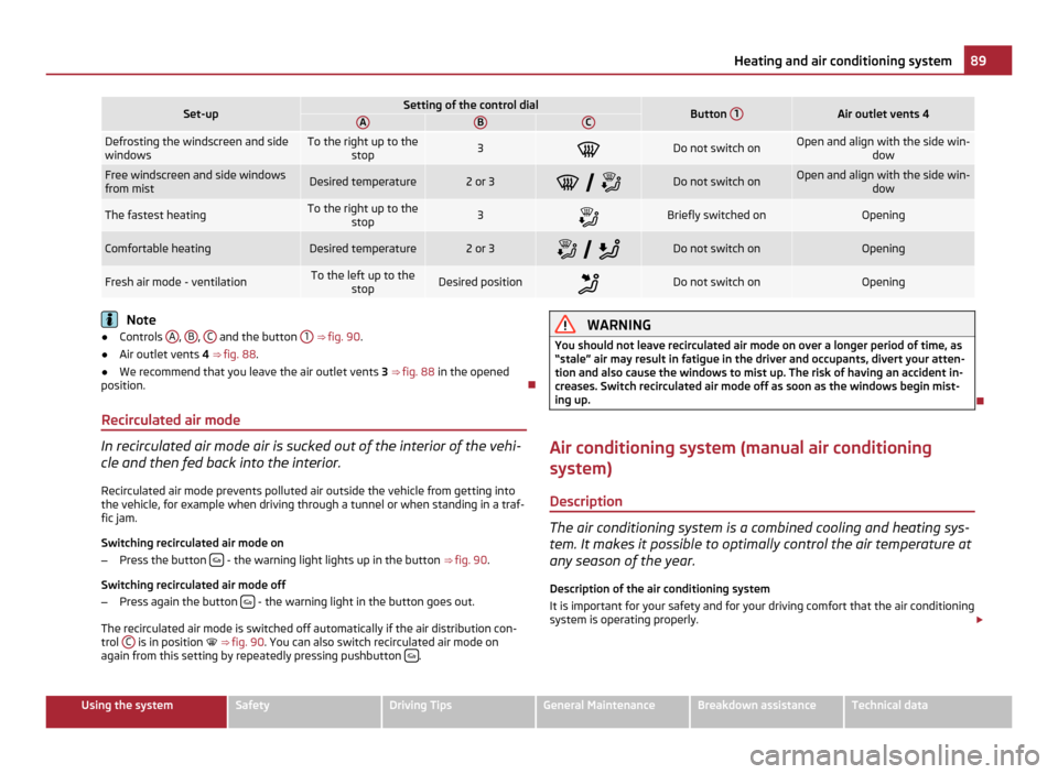
Set-up Setting of the control dial
Button
1 Air outlet vents 4
A B C
Defrosting the windscreen and side
windows To the right up to the
stop 3
Do not switch on Open and align with the side win-
dowFree windscreen and side windows
from mist
Desired temperature 2 or 3
Do not switch on Open and align with the side win-
dowThe fastest heating To the right up to the
stop 3
Briefly switched on Opening
Comfortable heating Desired temperature 2 or 3
Do not switch on Opening
Fresh air mode - ventilation To the left up to the
stop Desired position
Do not switch on Opening
Note
● Controls A ,
B ,
C and the button
1 ⇒ fig. 90
.
● Air outlet vents 4 ⇒ fig. 88 .
● We recommend that you leave the air outlet vents 3 ⇒ fig. 88
in the opened
position.
Recirculated air mode In recirculated air mode air is sucked out of the interior of the vehi-
cle and then fed back into the interior.
Recirculated air mode prevents polluted air outside the vehicle from getting into
the vehicle, for example when driving through a tunnel or when standing in a traf-
fic jam.
Switching recirculated air mode on
– Press the button - the warning light lights up in the button
⇒ fig. 90 .
Switching recirculated air mode off
– Press again the button - the warning light in the button goes out.
The recirculated air mode is switched off automatically if the air distribution con-
trol C is in position
⇒
fig. 90 . You can also switch recirculated air mode on
again from this setting by repeatedly pressing pushbutton . WARNING
You should not leave recirculated air mode on over a longer period of time, as
“stale
” air may result in fatigue in the driver and occupants, divert your atten-
tion and also cause the windows to mist up. The risk of having an accident in-
creases. Switch recirculated air mode off as soon as the windows begin mist-
ing up.
Air conditioning system (manual air conditioning
system) Description The air conditioning system is a combined cooling and heating sys-
tem. It makes it possible to optimally control the air temperature at
any season of the year.
Description of the air conditioning system
It is important for your safety and for your driving comfort that the air conditioning
system is operating properly. £ 89
Heating and air conditioning system Using the system Safety Driving Tips General Maintenance Breakdown assistance Technical data
Page 93 of 252
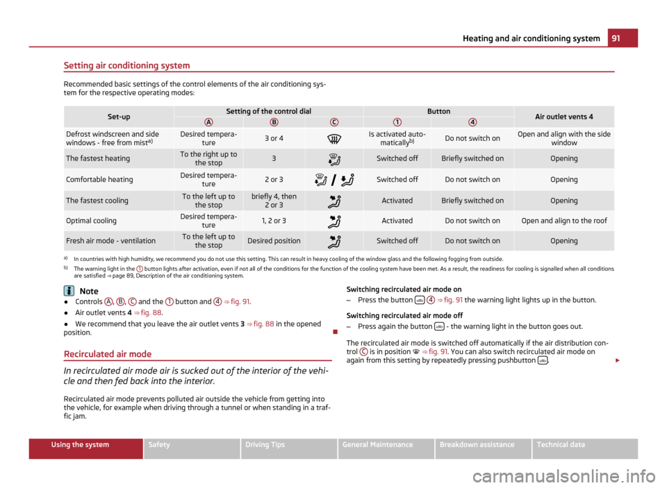
Setting air conditioning system
Recommended basic settings of the control elements of the air conditioning sys-
tem for the respective operating modes: Set-up Setting of the control dial Button
Air outlet vents 4
A B C 1 4
Defrost windscreen and side
windows - free from mist
a) Desired tempera-
ture 3 or 4
Is activated auto-
matically b) Do not switch on Open and align with the side
window The fastest heating To the right up to
the stop 3
Switched off Briefly switched on Opening
Comfortable heating Desired tempera-
ture 2 or 3
Switched off Do not switch on Opening
The fastest cooling To the left up to
the stop briefly 4, then
2 or 3 Activated Briefly switched on Opening
Optimal cooling Desired tempera-
ture 1, 2 or 3
Activated Do not switch on Open and align to the roof
Fresh air mode - ventilation To the left up to
the stop Desired position
Switched off Do not switch on Opening
a)
In countries with high humidity, we recommend you do not use this setting. This can result in heavy cooling of the window glass and the following fogging from outside.
b) The warning light in the 1 button lights after activation, even if not all of the conditions for the function of the cooling system have been met. As a result, the readiness for cooling is signalled when all conditions
are satisfied ⇒ page 89
, Description of the air conditioning system. Note
● Controls A ,
B ,
C and the
1 button and
4 ⇒
fig. 91 .
● Air outlet vents 4 ⇒
fig. 88 .
● We recommend that you leave the air outlet vents 3 ⇒ fig. 88
in the opened
position.
Recirculated air mode In recirculated air mode air is sucked out of the interior of the vehi-
cle and then fed back into the interior.
Recirculated air mode prevents polluted air outside the vehicle from getting into
the vehicle, for example when driving through a tunnel or when standing in a traf-
fic jam. Switching recirculated air mode on
– Press the button
4 ⇒ fig. 91
the warning light lights up in the button.
Switching recirculated air mode off
– Press again the button - the warning light in the button goes out.
The recirculated air mode is switched off automatically if the air distribution con-
trol C is in position ⇒
fig. 91 . You can also switch recirculated air mode on
again from this setting by repeatedly pressing pushbutton .
£ 91
Heating and air conditioning system Using the system Safety Driving Tips General Maintenance Breakdown assistance Technical data
Page 95 of 252
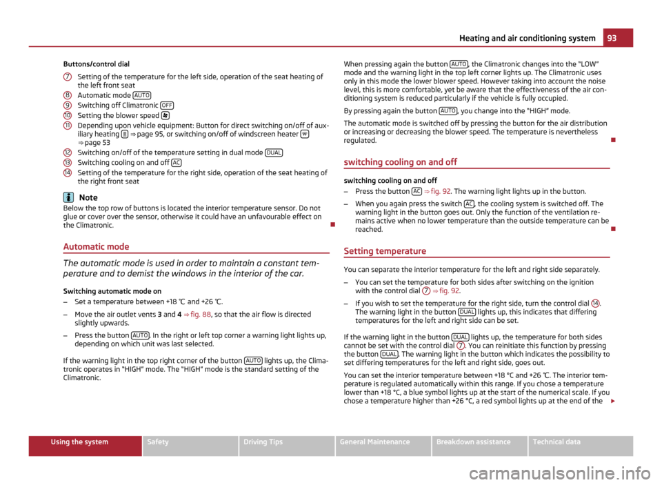
Buttons/control dial
Setting of the temperature for the left side, operation of the seat heating of
the left front seat
Automatic mode AUTOSwitching off Climatronic
OFFSetting the blower speed
Depending upon vehicle equipment: Button for direct switching on/off of aux-
iliary heating ⇒
page 95, or switching on/off of windscreen heater ⇒ page 53
Switching on/off of the temperature setting in dual mode
DUALSwitching cooling on and off
ACSetting of the temperature for the right side, operation of the seat heating of
the right front seat
Note
Below the top row of buttons is located the interior temperature sensor. Do not
glue or cover over the sensor, otherwise it could have an unfavourable effect on
the Climatronic.
Automatic mode The automatic mode is used in order to maintain a constant tem-
perature and to demist the windows in the interior of the car.
Switching automatic mode on
– Set a temperature between +18 ℃ and +26 ℃.
– Move the air outlet vents 3 and 4 ⇒
fig. 88 , so that the air flow is directed
slightly upwards.
– Press the button AUTO . In the right or left top corner a warning light lights up,
depending on which unit was last selected.
If the warning light in the top right corner of the button AUTO lights up, the Clima-
tronic operates in
“HIGH” mode. The “HIGH” mode is the standard setting of the
Climatronic. 7 8
9
10
11
12
13
14 When pressing again the button
AUTO , the Climatronic changes into the “LOW”
mode and the warning light in the top left corner lights up. The Climatronic uses
only in this mode the lower blower speed. However taking into account the noise
level, this is more comfortable, yet be aware that the effectiveness of the air con-
ditioning system is reduced particularly if the vehicle is fully occupied.
By pressing again the button AUTO , you change into the “HIGH” mode.
The automatic mode is switched off by pressing the button for the air distribution
or increasing or decreasing the blower speed. The temperature is nevertheless
regulated.
switching cooling on and off switching cooling on and off
–
Press the button AC
⇒
fig. 92 . The warning light lights up in the button.
– When you again press the switch AC , the cooling system is switched off. The
warning light in the button goes out. Only the function of the ventilation re-
mains active when no lower temperature than the outside temperature can be
reached.
Setting temperature You can separate the interior temperature for the left and right side separately.
–
You can set the temperature for both sides after switching on the ignition
with the control dial 7
⇒ fig. 92 .
– If you wish to set the temperature for the right side, turn the control dial 14 .
The warning light in the button DUAL lights up, this indicates that differing
temperatures for the left and right side can be set.
If the warning light in the button DUAL lights up, the temperature for both sides
cannot be set with the control dial 7 . You can reinitiate this function by pressing
the button DUAL . The warning light in the button which indicates the possibility to
set differing temperatures for the left and right side, goes out.
You can set the interior temperature between +18 °C and +26 ℃. The interior tem-
perature is regulated automatically within this range. If you chose a temperature
lower than +18 °C, a blue symbol lights up at the start of the numerical scale. If you
chose a temperature higher than +26 °C, a red symbol lights up at the end of the £ 93
Heating and air conditioning system Using the system Safety Driving Tips General Maintenance Breakdown assistance Technical data
Page 97 of 252
Defrosting windscreen
Defrosting windscreen - switching on
–
Press the button ⇒ fig. 92
.
– Press the button ⇒
fig. 92 .
Defrosting windscreen - switching off
– Once again press the button or the button
AUTO .
– Once again press the button .
The temperature control is controlled automatically. More air flows out of the air
outlet vents 1 and 2.
Auxiliary heating (auxiliary heating and ventilation)
Description and important information The auxiliary heating (auxiliary heating and ventilation) heats or
supplies the interior of the vehicle with fresh air independent of the
engine.
Auxiliary heating (auxiliary heating)
The auxiliary heater (parking heater) functions in connection with the air-condi-
tioning system or Climatronic.
It can be used when stationary, when engine is switched off for preheating of the
vehicle as well as while driving (e.g. during the heating phase of the engine).
The engine is also preheated when the vehicle is stationary and the engine is
switched off, if the auxiliary heating is switched on.
The auxiliary heating (auxiliary heating) warms up the coolant during the combus-
tion of fuel from the vehicle tank. The coolant warms up the air, which (if the
blower speed is not set to zero) flows into the occupant compartment.
Auxiliary ventilation
The auxiliary ventilation enables fresh air to flow into the vehicle interior by
switching off the engine, whereby the interior temperature is effectively de-
creased (e.g. with the vehicle parked in the sun). WARNING
● The auxiliary heating must never be operated in closed rooms - risk of poi-
soning!
● The auxiliary heating must not be running during refuelling - risk of fire.
● The exhaust pipe of the auxiliary heating is located on the underside of
the vehicle. Therefore do not place the vehicle, if you wish to operate the aux-
iliary heating, in such a way that the exhaust gases of the auxiliary heating
can come easily into contact with inflammable materials (e.g. dry grass) or
easily inflammable substances (e.g. fuel run out). Note
If the auxiliary heating runs, the fuel consumption comes from the vehicle tank.
The auxiliary heating automatically controls the filling level in the fuel tank. If only
a low quantity of fuel is present in the fuel tank, the function of the auxiliary heat-
ing is blocked.
● The exhaust pipe of the auxiliary heating, which is located on the underside of
the vehicle, must not be clogged and the exhaust flow must not be blocked.
● If the auxiliary heating and ventilation is running, the vehicle battery discharg-
es. If the auxiliary heating and ventilation has been operated several times over a
longer period, the vehicle must be driven a few kilometres in order to recharge the
vehicle battery.
● The auxiliary heating only switches the blower on, if it has achieved a coolant
temperature of approx. 50
°C.
● At low outside temperatures, this can result in a formation of water vapour in
the area of the engine compartment. This is quite normal and is not an operating
problem.
● After switching off the auxiliary heating, the coolant pump runs for a short pe-
riod.
● The auxiliary heating and ventilation does not switch on or comes on, if the
vehicle battery indicates a low loading state.
● The auxiliary heating (auxiliary heating) does not switch on, if the following
was shown in the information display or before switching off the ignition: Please
refuel! £ 95
Heating and air conditioning system Using the system Safety Driving Tips General Maintenance Breakdown assistance Technical data
Page 99 of 252
If the system is running, a warning light in the button for direct switching on/off
of the auxiliary heating
lights up.
The running system deactivates after expiration of the operating period or is de-
activated earlier by pressing the button for direct switching on/off of the auxiliary
heating ⇒
page 96.
A random pre-set time can be deactivated by selecting the menu point Deactivate
in the menu Activate.
After selecting the menu Factory setting in the menu Aux. heating, it is possible
to return to the factory setting.
Radio remote control The auxiliary heating (auxiliary heating and ventilation) can be
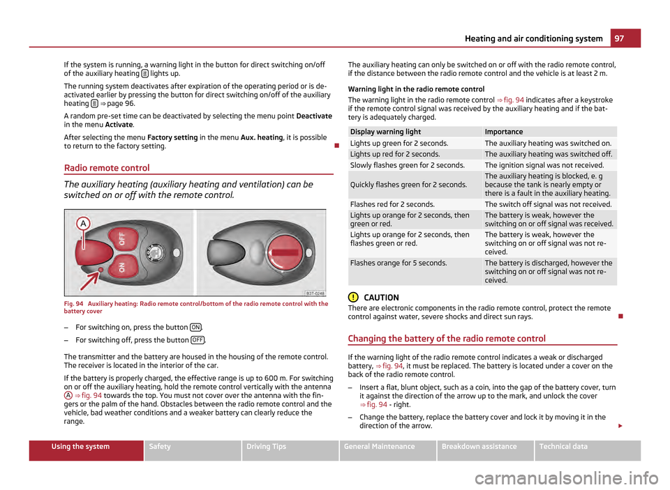
switched on or off with the remote control. Fig. 94 Auxiliary heating: Radio remote control/bottom of the radio remote control with the
battery cover
–
For switching on, press the button ON .
– For switching off, press the button OFF .
The transmitter and the battery are housed in the housing of the remote control.
The receiver is located in the interior of the car.
If the battery is properly charged, the effective range is up to 600
m. For switching
on or off the auxiliary heating, hold the remote control vertically with the antenna A
⇒ fig. 94 towards the top. You must not cover over the antenna with the fin-
gers or the palm of the hand. Obstacles between the radio remote control and the
vehicle, bad weather conditions and a weaker battery can clearly reduce the
range. The auxiliary heating can only be switched on or off with the radio remote control,
if the distance between the radio remote control and the vehicle is at least 2 m.
Warning light in the radio remote control
The warning light in the radio remote control ⇒ fig. 94 indicates after a keystroke
if the remote control signal was received by the auxiliary heating and if the bat-
tery is adequately charged. Display warning light Importance
Lights up green for 2 seconds. The auxiliary heating was switched on.
Lights up red for 2 seconds. The auxiliary heating was switched off.
Slowly flashes green for 2 seconds. The ignition signal was not received.
Quickly flashes green for 2 seconds. The auxiliary heating is blocked, e. g
because the tank is nearly empty or
there is a fault in the auxiliary heating.
Flashes red for 2 seconds. The switch off signal was not received.
Lights up orange for 2 seconds, then
green or red. The battery is weak, however the
switching on or off signal was received.
Lights up orange for 2 seconds, then
flashes green or red. The battery is weak, however the
switching on or off signal was not re-
ceived.
Flashes orange for 5 seconds. The battery is discharged, however the
switching on or off signal was not re-
ceived. CAUTION
There are electronic components in the radio remote control, protect the remote
control against water, severe shocks and direct sun rays.
Changing the battery of the radio remote control If the warning light of the radio remote control indicates a weak or discharged
battery,
⇒ fig. 94 , it must be replaced. The battery is located under a cover on the
back of the radio remote control.
– Insert a flat, blunt object, such as a coin, into the gap of the battery cover, turn
it against the direction of the arrow up to the mark, and unlock the cover
⇒ fig. 94 - right.
– Change the battery, replace the battery cover and lock it by moving it in the
direction of the arrow. £ 97
Heating and air conditioning system Using the system Safety Driving Tips General Maintenance Breakdown assistance Technical data