ESP SKODA YETI 2014 1.G / 5L User Guide
[x] Cancel search | Manufacturer: SKODA, Model Year: 2014, Model line: YETI, Model: SKODA YETI 2014 1.G / 5LPages: 248, PDF Size: 29.49 MB
Page 56 of 248
›Pull on door handle A
» Fig. 34 on the door you wish to open.
Opening from the inside›
Pull on door opening lever
B
of the respective door and push the door away
from you.
Closing from the inside
›
Grasp pull handle
C
and close the door.
WARNING■ Make sure that the door has closed correctly as it can open suddenly
while driving – risk of death!■
Only open and close the door when there is no one in the opening/closing
range – risk of injury!
■
An opened door can close automatically if there is a strong wind or the
vehicle is on an incline – risk of injury!
■
Never drive with the doors open - it can be fatal!
Unlocking / locking - KESSY
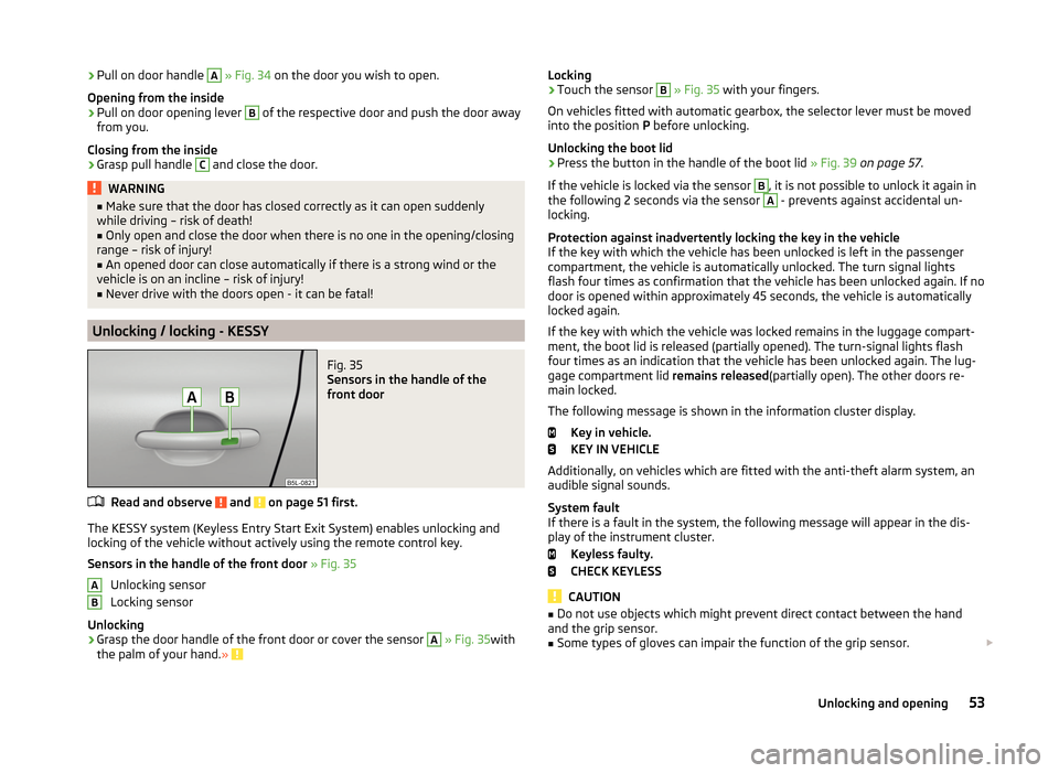
Fig. 35
Sensors in the handle of the
front door
Read and observe and on page 51 first.
The KESSY system (Keyless Entry Start Exit System) enables unlocking and
locking of the vehicle without actively using the remote control key.
Sensors in the handle of the front door » Fig. 35
Unlocking sensor
Locking sensor
Unlocking
›
Grasp the door handle of the front door or cover the sensor
A
» Fig. 35 with
the palm of your hand. »
ABLocking›Touch the sensor B » Fig. 35 with your fingers.
On vehicles fitted with automatic gearbox, the selector lever must be moved
into the position P before unlocking.
Unlocking the boot lid›
Press the button in the handle of the boot lid » Fig. 39 on page 57 .
If the vehicle is locked via the sensor
B
, it is not possible to unlock it again in
the following 2 seconds via the sensor
A
- prevents against accidental un-
locking.
Protection against inadvertently locking the key in the vehicle
If the key with which the vehicle has been unlocked is left in the passenger
compartment, the vehicle is automatically unlocked. The turn signal lights
flash four times as confirmation that the vehicle has been unlocked again. If no
door is opened within approximately 45 seconds, the vehicle is automatically
locked again.
If the key with which the vehicle was locked remains in the luggage compart-
ment, the boot lid is released (partially opened). The turn-signal lights flash
four times as an indication that the vehicle has been unlocked again. The lug-
gage compartment lid remains released(partially open). The other doors re-
main locked.
The following message is shown in the information cluster display. Key in vehicle.
KEY IN VEHICLE
Additionally, on vehicles which are fitted with the anti-theft alarm system, an audible signal sounds.
System fault
If there is a fault in the system, the following message will appear in the dis- play of the instrument cluster.
Keyless faulty.
CHECK KEYLESS
CAUTION
■ Do not use objects which might prevent direct contact between the hand
and the grip sensor.■
Some types of gloves can impair the function of the grip sensor.
53Unlocking and opening
Page 58 of 248

Unlocking / locking » Fig. 36
Locking
Unlocking
If the icon in the button
is lit, the vehicle is locked.
If the icon in the button
is not lit, the vehicle is not locked.
The central locking system also operates if the ignition is switched off.
The following applies after locking.
› Opening the doors and the boot lid from the outside is not possible.
› The doors can be unlocked and opened from the inside by a single pull on the
opening lever of the respective door.
› In the event of an accident in which the airbags are deployed, the locked
doors are automatically unlocked in order to enable rescuers to gain access
to the vehicle.WARNING■ Doors locked from the inside make it difficult for rescuers to get into the
vehicle in an emergency – risk to life!■
If the Safelock system is switched on » page 54, the door opening levers
and the central locking buttons do not operate.
CAUTION
If at least one door has been opened, the vehicle cannot be locked.
Child safety lock
Fig. 37
Back door: left / right
Read and observe and on page 51 first.
The child safety lock prevents the rear door from being opened from the in- side. The door can only be opened from the outside.
Switching the child safety system on and off » Fig. 37
Switching on
Switching off
You can switch the child safety lock on and off using the vehicle key.
Malfunctions
Read and observe
and on page 51 first.
Failure of the central locking
If the central locking system fails, only the driver's door can be locked / un-
locked with the key. The other doors and the tailgate can be emergency-
locked or unlocked.
› Unlocking / locking
» page 52 for vehicles without remote control.
› Unlocking / locking for vehicles with remote control
» page 211.
› Emergency locking of the door
» page 211.
› Emergency unlocking of the boot lid
» page 212.
Displaying an error
If the warning light in the driver's door initially flashes quickly for around 2 sec-
onds, and then lights up for 30 seconds without interruption before flashing
again slowly, you will need to seek the assistance of a specialist garage.
Discharged battery in the remote control key
If the red indicator light
B
» Fig. 33 on page 52 does not flash when you press
a button on the remote control key, the battery is empty.
If the voltage of the battery in the remote control key is too low, the following
message appears in the display of the instrument cluster.
Renew key battery!
KEY BATTERY
Replace the battery » page 210.
55Unlocking and opening
Page 62 of 248
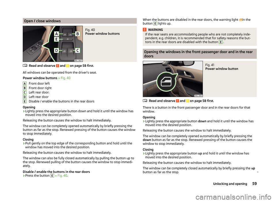
Open / close windowsFig. 40
Power window buttons
Read and observe and on page 58 first.
All windows can be operated from the driver's seat.
Power window buttons » Fig. 40
Front door left
Front door right
Left rear door:
Left rear door
Disable / enable the buttons in the rear doors
Opening
›
Lightly press the appropriate button down and hold it until the window has
moved into the desired position.
Releasing the button causes the window to halt immediately.
The window can be completely opened automatically by briefly pressing the
button as far as the stop. Renewed pressing of the button causes the window
to stop immediately.
Closing
›
Pull gently on the top edge of the corresponding button and hold until the
window has moved into the desired position.
Releasing the button causes the window to halt immediately.
The window can also be fully closed automatically by pulling the button up to
the stop. Renewed pulling of the button causes the window to stop immedi-
ately.
Disable / enable the buttons in the rear doors
›
Press the button
E
» Fig. 40 .
ABCDEWhen the buttons are disabled in the rear doors, the warning light in the
button E lights up.WARNINGIf the rear seats are accommodating people who are not completely inde-
pendent, e.g. children, it is recommended that for safety reasons the but-
tons in the rear doors are disabled with the button E
.
Opening the windows in the front passenger door and in the rear
doors
Fig. 41
Power window button
Read and observe and on page 58 first.
There is a button in the front passenger door and in the rear doors for that
window.
Opening
›
Lightly press the appropriate button down and hold it until the window has
moved into the desired position.
Releasing the button causes the window to halt immediately.
The window can be completely opened automatically by briefly pressing the
down button as far as the stop. Renewed pressing of the button causes the
window to stop immediately.
Closing
›
Lightly press the appropriate button up and hold it until the window has
moved into the desired position.
Releasing the button causes the window to halt immediately.
The window can be completely closed automatically by briefly pressing the up
button as far as the stop.
59Unlocking and opening
Page 66 of 248
›Press the button
and hold down.
› The sun screen opens and closes again after around 10 seconds.
› Release the button.
Convenience operation of sliding / tilting roof
Read and observe
on page 61 first.
The sliding / tilting roof can be operated by locking or unlocking using the keyor using the KESSY system with the aid of the sensor
A
--
» Fig. 35 on page 53 .
Closing
The sliding/tilting roof can be closed as follows.
›
Press and hold the symbol button on the key.
›
Hold the key in the driver's lock in the lock position.
›
In the KESSY system, hold a finger on the sensor
B
» Fig. 35 on page 53 .
By releasing the lock or lifting your finger off the sensor
B
when using the
KESSY system, the closing process is immediately interrupted.
Tilting roof
›
Press and hold the symbol button on the key.
WARNINGClose the sliding/tilting roof carefully – risk of injury! The force limiter does
not work when convenience closing is in operation.
Note
The sliding/tilting roof cannot be opened using the convenience operating fea-
ture.Lights and visibility
Lights
Introduction
This chapter contains information on the following subjects:
Operating the lights
64
Daylight running lights (DAY LIGHT)
65
Turn signal and main beam
65
Automatic driving lamp control
66
Adaptive headlights (AFS)
66
Fog lights
67
Fog lights with the CORNER function
67
Rear fog light
67
COMING HOME / LEAVING HOME
68
Hazard warning light system
68
Parking lights
69
Instrument lighting
69
Driving abroad
69
Unless otherwise stated, the lights only work when the ignition is switched on.
The arrangement of the controls right-hand drive models may differ from the
layout shown in » Fig. 45 on page 64 . The symbols which mark the positions
of the controls are identical.
Keep the headlights lenses clean. The following guidelines must be ob-
served » page 172 , Headlight glasses .
WARNING■
The activation of the lights should only be undertaken in accordance with
national legal requirements.■
The driver is always responsible for the correct settings and use of the
lights.
63Lights and visibility
Page 67 of 248
WARNING (Continued)■The automatic driving lamp control only operates as a support and
does not release the driver from his responsibility to check the lights and, if
necessary, to switch on the light depending on the prevailing light condi-
tions. The light sensor cannot, for example, detect rain or snow. Under
these conditions we recommend switching on the low beam or fog lights!■
Never drive with only the side lights on! The side lights are not bright
enough to light up the road sufficiently in front of you or to be seen by oth-
er oncoming traffic. Therefore always switch on the low beam when it is
dark or if visibility is poor.
Note
The headlights may mist up temporarily. When the driving lights are switched
on, the light outlet surfaces are free from mist after a short period, although
the headlight lenses may still be misted up in the peripheral areas. This mist
has no influence on the life of the lighting system.
Operating the lights
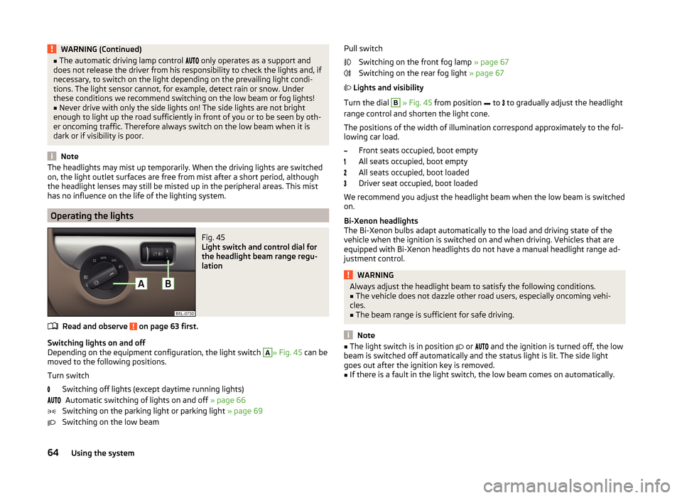
Fig. 45
Light switch and control dial for
the headlight beam range regu-
lation
Read and observe on page 63 first.
Switching lights on and off
Depending on the equipment configuration, the light switch
A
» Fig. 45 can be
moved to the following positions.
Turn switch Switching off lights (except daytime running lights)Automatic switching of lights on and off » page 66
Switching on the parking light or parking light » page 69
Switching on the low beam
Pull switch
Switching on the front fog lamp » page 67
Switching on the rear fog light » page 67
Lights and visibility
Turn the dial B
» Fig. 45 from position
to
to gradually adjust the headlight
range control and shorten the light cone.
The positions of the width of illumination correspond approximately to the fol-
lowing car load.
Front seats occupied, boot empty
All seats occupied, boot empty
All seats occupied, boot loaded
Driver seat occupied, boot loaded
We recommend you adjust the headlight beam when the low beam is switched
on.
Bi-Xenon headlights
The Bi-Xenon bulbs adapt automatically to the load and driving state of the
vehicle when the ignition is switched on and when driving. Vehicles that are
equipped with Bi-Xenon headlights do not have a manual headlight range ad-
justment control.
WARNINGAlways adjust the headlight beam to satisfy the following conditions.■The vehicle does not dazzle other road users, especially oncoming vehi-
cles.■
The beam range is sufficient for safe driving.
Note
■ The light switch is in position or and the ignition is turned off, the low
beam is switched off automatically and the status light is lit. The side light
goes out after the ignition key is removed.■
If there is a fault in the light switch, the low beam comes on automatically.
64Using the system
Page 70 of 248
The mode is active when the wipers operate continuously for longer than 2 mi-
nutes at a speed of 20 - 70 km / h. The mode is deactivated when the wind-
screen wipers are switched off for longer than 8 minutes.
Dynamic cornering lights
The cone of light in front of the vehicle is adjusted to the steering angle so
that the road in the curve is illuminated. This function is active at speeds
greater than 10 km.h and in all AFS modes.
Tourist lights (Travel mode)
This mode makes it possible to drive in countries with opposing traffic system
(driving on the left/right) without dazzling the oncoming vehicles.
When this mode is active, the above-mentioned modes and the side swivel of
the headlights is deactivated.
This mode can be enabled or disabled via the MAXI DOT display in the Travel
mode » page 47 , Settings menu option.WARNINGIf the AFS system is defective, the headlights are automatically lowered to
the emergency position, which prevents a possible dazzling of oncoming
traffic. This reduces the cone of light in front of the vehicle. Drive carefully
and visit a specialist garage as soon as possible.
Note
When the “tourist light” mode is active, the warning light flashes for 10 sec-
onds each time the ignition is switched on.
Fog lights
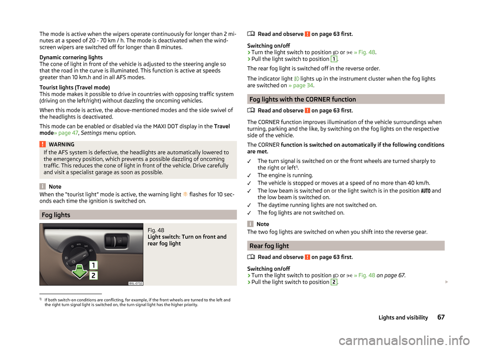
Fig. 48
Light switch: Turn on front and
rear fog light
Read and observe on page 63 first.
Switching on/off
›
Turn the light switch to position
or
» Fig. 48 .
›
Pull the light switch to position
1
.
The rear fog light is switched off in the reverse order.
The indicator light
lights up in the instrument cluster when the fog lights
are switched on » page 34.
Fog lights with the CORNER function
Read and observe
on page 63 first.
The CORNER function improves illumination of the vehicle surroundings when
turning, parking and the like, by switching on the fog lights on the respective
side of the vehicle.
The CORNER function is switched on automatically if the following conditions
are met.
The turn signal is switched on or the front wheels are turned sharply to
the right or left 1)
.
The engine is running.
The vehicle is stopped or moves at a speed of no more than 40 km/h.
The low beam is switched on or the light switch is in the position and
the low beam is switched on.
The daytime running lights are not switched on.
The fog lights are not switched on.
Note
The two fog lights are switched on when you shift into the reverse gear.
Rear fog light
Read and observe
on page 63 first.
Switching on/off
›
Turn the light switch to position or
» Fig. 48 on page 67 .
›
Pull the light switch to position
2
.
1)
If both switch-on conditions are conflicting, for example, if the front wheels are turned to the left and
the right turn signal light is switched on, the turn signal light has the higher priority.
67Lights and visibility
Page 72 of 248

If one of the airbags is deployed, the hazard warning light system will switch
on automatically.
If the turn signal light is switched on when the hazard warning light and the
ignition are both switched on, then only the turn signal light on the corre-
sponding vehicle side will flash.WARNINGSwitch on the hazard warning light system if, for example, the following oc-
curs.■
You encounter a traffic congestion.
■
The vehicle has broken down.
Parking lights
Read and observe
on page 63 first.
The parking light is provided for a temporary lighting of the parked vehicle.
Parking light switching on
›
Switch off the ignition.
›
Place the control lever into position
A
or
B
as far as it can go
» Fig. 46 on
page 65 - the parking light on the right/left-hand side of the vehicle is
switched on.
If the right or left turn signal light has been switched on and the ignition is
switched off, the parking light is not automatically switched on.
Switching on the side light on both sides
›
Switch off the ignition.
›
Turn the light switch
A
to position
» Fig. 45 on page 64 and lock the ve-
hicle.
After pulling out the ignition key and opening the driver's door, an audible
warning sounds. After a few seconds or after closing the driver's door, the au-
dible alarm is turned off, but the parking lights will remain switched on.
CAUTION
Turning on the parking light means the battery is heavily loaded, especially
over short distances.Instrument lightingFig. 50
Controls for the instrument
lighting
Read and observe on page 63 first.
The brightness of the instrument lights can be set only if the parking, low
beam or high beam is switched on.
Turning the knob » Fig. 50
Adjust brightness of the instrument lighting.
Note
On vehicles with MAXI DOT display » page 47 the brightness of the instrument
lighting is set automatically. A manual brightness adjustment can therefore
only have a limited effect.
Driving abroad
Read and observe
on page 63 first.
The low beam is set asymmetrically. It illuminates the side of the road on
which the vehicle is being driven to a greater extent.
When driving in countries with opposing traffic system (traffic on the left/
right), asymmetric headlight adjustment can dazzle oncoming traffic. In order
to avoid this, the headlights must be adjusted at a specialist garage.
You can adjust the headlights with Xenon lights in the menu of the MAXI DOT
display under the menu point Travel mode » page 47 , Settings .
Note
You can find out more information on adjusting the headlights at a specialist
garage.69Lights and visibility
Page 75 of 248
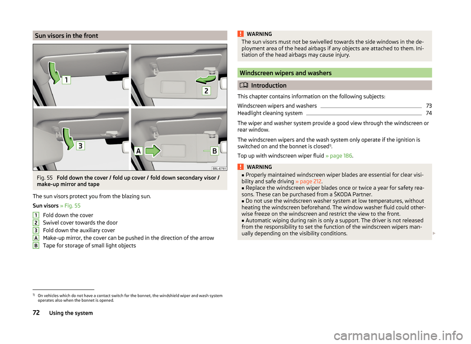
Sun visors in the frontFig. 55
Fold down the cover / fold up cover / fold down secondary visor /
make-up mirror and tape
The sun visors protect you from the blazing sun.
Sun visors » Fig. 55
Fold down the cover
Swivel cover towards the door
Fold down the auxiliary cover
Make-up mirror, the cover can be pushed in the direction of the arrow
Tape for storage of small light objects
123ABWARNINGThe sun visors must not be swivelled towards the side windows in the de-
ployment area of the head airbags if any objects are attached to them. Ini-
tiation of the head airbags may cause injury.
Windscreen wipers and washers
Introduction
This chapter contains information on the following subjects:
Windscreen wipers and washers
73
Headlight cleaning system
74
The wiper and washer system provide a good view through the windscreen or
rear window.
The windscreen wipers and the wash system only operate if the ignition is
switched on and the bonnet is closed 1)
.
Top up with windscreen wiper fluid » page 186.
WARNING■
Properly maintained windscreen wiper blades are essential for clear visi-
bility and safe driving » page 212.■
Replace the windscreen wiper blades once or twice a year for safety rea-
sons. These can be purchased from a ŠKODA Partner.
■
Do not use the windscreen washer system at low temperatures, without
heating the windscreen beforehand. The window washer fluid could other-
wise freeze on the windscreen and restrict the view to the front.
■
Automatic wiping during rain is only a support. The driver is not released
from the responsibility to set the function of the windscreen wipers man-
ually depending on the visibility conditions.
1)
On vehicles which do not have a contact switch for the bonnet, the windshield wiper and wash system
operates also when the bonnet is opened.
72Using the system
Page 83 of 248

When automatic storage is activated, the current positions of the driver's seat
and the external mirrors are saved in the memory of the remote control key
each time the vehicle is locked. When the vehicle is next unlocked using the
same key, the driver's seat and the external mirrors assume the positions stor-
ed in the memory of this key 1)
.
Saving front passenger mirror settings when reversing
Above the MAXI DOT display in the menu item Mirror down The lowering func-
tion for the mirror on the passenger side when reversing must be ena-
bled » page 47 .›
Unlock the vehicle with the remote control key.
›
Switch on the ignition.
›
Adjust the rotary knob for the mirrors to the position
or in right-hand drive
to the position
» page 76 .
›
Engage reverse gear.
›
Adjust the front passenger's mirror to the desired position » page 76.
›
Disengage reverse gear.
The adjusted position of the exterior mirror is stored in the remote control key
memory.
Disable the function of automatic storage
›
Unlock the vehicle with the remote control key.
›
Press and hold the SET button
A
» Fig. 61 on page 79 . At the same time,
press the button on the remote control key within 10 seconds.
The successful deactivation of the automatic storage function for each key is confirmed by an acoustic signal.
Stopping the ongoing adjustment
›
Press any button on the driver's seat.
Or
›
Press the button on the remote control key.
Front seat functions
Introduction
This chapter contains information on the following subjects:
Front seat heating
80
Front armrest
81
Folding front passenger seat
81
Front seat heating
Fig. 62
Buttons for heating the front
seats
The seat backrests and seats can be heated electrically.
The seat heating can only be switched on when the engine is running.
Buttons for the seat heater » Fig. 62
Left seat heating
Right seat heating
Switching on
›
Press the corresponding symbol button or
» Fig. 62 .
Pressing once switches the seat heating on at its maximum level.
With repeated pressing of the switch, the intensity of the heating is reduced
until it is switched off.
The level of the seat heating is indicated by the number of illuminated warning
lights in the switch.
1)
The vehicle must be locked and unlocked with the same key to save the seat and exterior mirror position
to the key.
80Using the system
Page 85 of 248
WARNING■The front passenger airbag should be switched off when transporting ob-
jects on the seat which was folded forwards » page 22, Deactivating the
front passenger airbag .■
Adjust the seat backrest only when the vehicle is stationary.
■
When moving the seat backrest, make sure the seat backrest has been
properly secured – check by pulling on the seat backrest.
■
If the seat backrest is folded, passengers may only be transported on the
outer seat behind the driver.
■
When moving the seat backrest, keep limbs out of the area between the
seat and seat backrest – risk of injury!
■
Never transport the following items on the seat backrest when folded
forwards. ■ Objects that could restrict the driver's view.
■ Objects which make it impossible for the driver to control the vehicle,
e.g. if they roll under the pedals, or could protrude into the driver's zone.
■ Objects which could lead to injury to passengers due to a change of di-
rection or braking manoeuvre when accelerating sharply.
Head restraints
Introduction
This chapter contains information on the following subjects:
Adjusting, installing and removing the headrests.
82
Rear centre head restraints
83
The head restraints and the front seats must be adjusted to match the body
size at all times and the seat belt must always be fastened properly to provide
the most effective levels of protection to the passengers » page 9, Correct and
safe seated position .
Best protection is achieved if the top edge of the head rest is at the same level
as the upper part of your head.
WARNING■ With seats occupied, the respective head rests must be correctly set (may
not be in the bottom position) - risk of fatal injury!■
With seats occupied, the respective head rests must be installed and ad-
justed correctly - risk of fatal injury!
NoteThe position of the front and rear outer head restraints is adjustable in height.
The middle rear head restraint is only adjustable in two positions.
Adjusting, installing and removing the headrests.
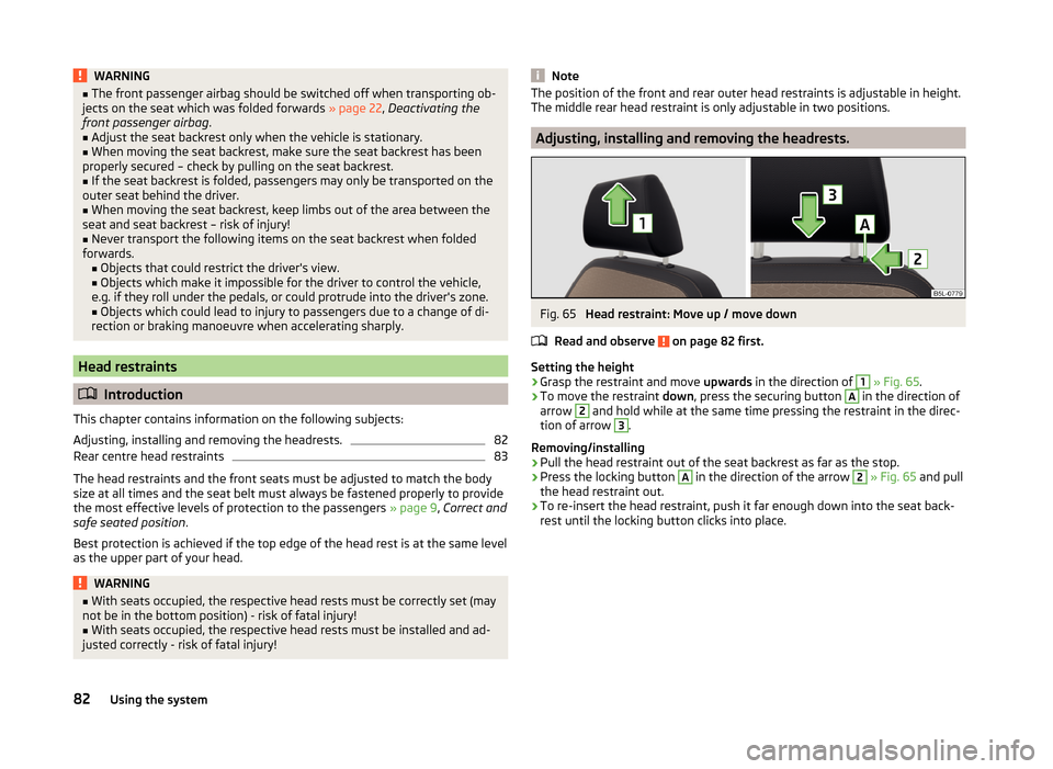
Fig. 65
Head restraint: Move up / move down
Read and observe
on page 82 first.
Setting the height
›
Grasp the restraint and move upwards in the direction of
1
» Fig. 65 .
›
To move the restraint down, press the securing button
A
in the direction of
arrow
2
and hold while at the same time pressing the restraint in the direc-
tion of arrow
3
.
Removing/installing
›
Pull the head restraint out of the seat backrest as far as the stop.
›
Press the locking button
A
in the direction of the arrow
2
» Fig. 65 and pull
the head restraint out.
›
To re-insert the head restraint, push it far enough down into the seat back-
rest until the locking button clicks into place.
82Using the system