ESP SKODA YETI 2014 1.G / 5L Owner's Guide
[x] Cancel search | Manufacturer: SKODA, Model Year: 2014, Model line: YETI, Model: SKODA YETI 2014 1.G / 5LPages: 248, PDF Size: 29.49 MB
Page 95 of 248
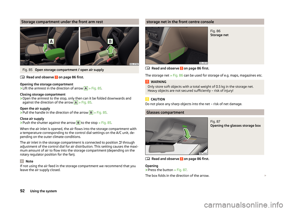
Storage compartment under the front arm restFig. 85
Open storage compartment / open air supply
Read and observe
on page 86 first.
Opening the storage compartment
›
Lift the armrest in the direction of arrow
A
» Fig. 85 .
Closing storage compartment
›
Open the armrest to the stop, only then can it be folded downwards and against the direction of the arrow
A
» Fig. 85 .
Open the air supply
›
Pull the handle in the direction of the arrow
B
» Fig. 85 .
Close air supply
›
Push the shutter against the arrow
B
to the stop » Fig. 85.
When the air inlet is opened, the air flows into the storage compartment with
a temperature corresponding to the control dial settings on the A/C unit, de-
pending on the outer climate conditions.
The air inlet in the storage compartment is connected to position through
adjustment of the control dial for air distribution. This setting causes the maxi-
mum amount of air to flow into the storage compartment (depending on the
rotary regulator position for the fan).
Note
If not using the air feed in the storage compartment we recommend that you
leave the air supply closed.storage net in the front centre consoleFig. 86
Storage net
Read and observe on page 86 first.
The storage net » Fig. 86 can be used for storage of e.g. maps, magazines etc.
WARNINGOnly store soft objects with a total weight of 0.5 kg in the storage net.
Heavy objects are not secured sufficiently – risk of injury!
CAUTION
Do not place any sharp objects into the net – risk of net damage.
Glasses compartment
Fig. 87
Opening the glasses storage box
Read and observe on page 86 first.
Opening
›
Press the button » Fig. 87.
The box folds in the direction of the arrow.
92Using the system
Page 99 of 248
›Place the empty through-loading bag in the gap between the front and rear
seats in such a way that the end of the bag with the zip lies in the boot.›
Open the tailgate.
›
Push the skis into the through-loading bag from the boot » .
›
Close the through-loading bag.
Securing through-loading bag and skis
›
Pull the securing belt with both lock tongues out of the pocket of the
through-loading bag.
›
Insert the lock tongues
A
» Fig. 94 in the belt locks of the rear middle seat
belt
C
, first on the one side and then on the other side.
›
Place the securing belt in the middle of the skis between the heel and the tip
of the bindings and pull the securing belt tight at the free end of the belt
B
.
WARNING■ After placing the skis into the through-loading bag, you must secure the
through-loading bag with the securing belt.■
The securing belt must hold the skis tight.
■
Ensure that the securing belt for skis grasps the middle between the tip
and the heel element of the binding (see also marking on the through-load-
ing bag).
■
The total weight of the skis which are transported must not exceed 10 kg.
CAUTION
■ Never fold and stow the through-loading bag wet - risk of damaging the
through-loading bag.■
The through-loading bag is designed to hold max. two pairs of skis.
■
Place the skis and sticks in the through-loading bag with the tips facing to
the rear.
Luggage compartment
Introduction
This chapter contains information on the following subjects:
Fastening elements
97
Fixing nets
97
Foldable hook
98
Fastening bar with sliding hook
98
Flexible storage compartment
98
Floor covering on both sides
99Luggage compartment cover99Net partition100
Storage compartments
100
Removable storage box
101
Removable light
101
Class N1 vehicles
102
Please observe the following for the purpose of maintaining good handling
characteristics of your vehicle:
›
Distribute loads as evenly as possible.
›
Place heavy objects as far forward as possible.
›
Attach the items of luggage to the lashing eyes or by using the fixing
nets » page 97 .
In the event of an accident, even small and light objects gain so much kinetic
energy that they can cause severe injuries.
The magnitude of the kinetic energy is dependent on the speed at which the
vehicle is travelling and the weight of the object.
Example: In the event of a frontal collision at a speed of 50 km/h, an object
with a weight of 4.5 kg produces an energy, which corresponds to 20 times its
own weight. This means that it results in a weight of approx. 90 kg “ ”.
WARNING■ Always store transported objects in the boot and attach them to the lash-
ing eyes.■
Loose objects can be thrown forward during a sudden manoeuvre or in
case of an accident and can injure the occupants or other road users.
■
Loose objects could hit a deployed airbag and injure occupants – danger
of death!
■
Please note that transporting heavy objects alters the handling proper-
ties of the vehicle due to the displacement of the centre of gravity – risk of
accident! The speed and style of driving must be adjusted accordingly.
■
If the items of luggage or objects are attached to the lashing eyes with
unsuitable or damaged lashing straps, injuries can occur in the event of
braking manoeuvres or accidents. To prevent items of luggage from moving
around, always use suitable lashing straps which must be firmly attached
to the lashing eyes.
96Using the system
Page 110 of 248
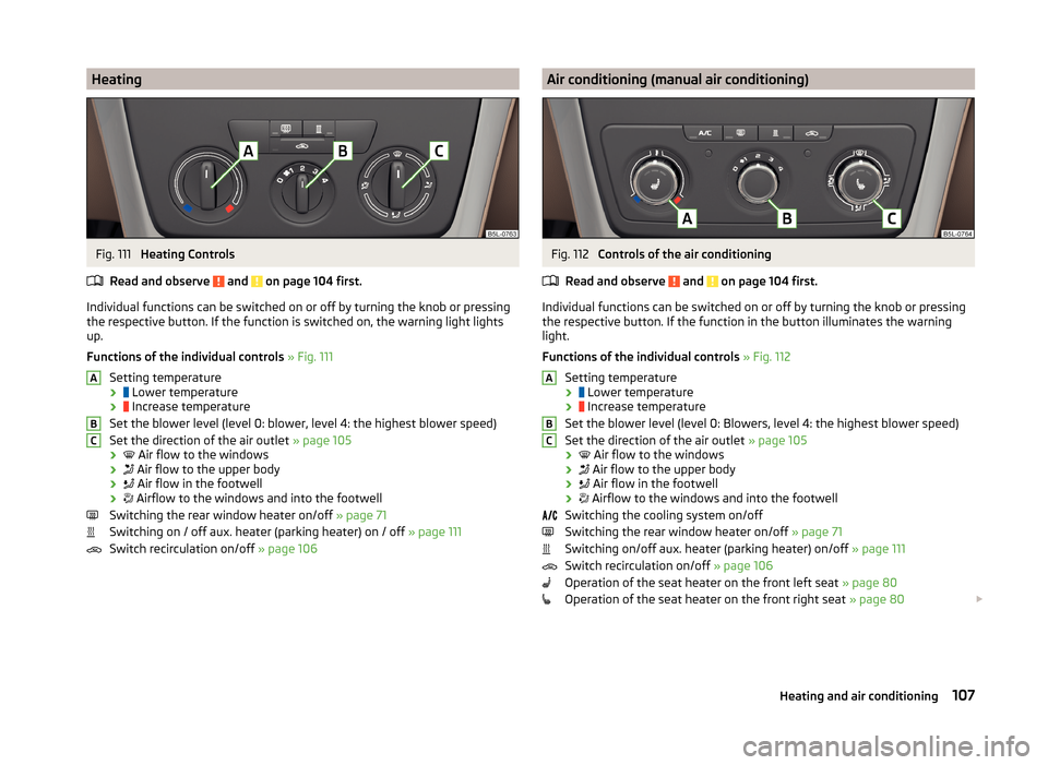
HeatingFig. 111
Heating Controls
Read and observe
and on page 104 first.
Individual functions can be switched on or off by turning the knob or pressing the respective button. If the function is switched on, the warning light lights
up.
Functions of the individual controls » Fig. 111
Setting temperature ›
Lower temperature
›
Increase temperature
Set the blower level (level 0: blower, level 4: the highest blower speed)
Set the direction of the air outlet » page 105
›
Air flow to the windows
›
Air flow to the upper body
›
Air flow in the footwell
›
Airflow to the windows and into the footwell
Switching the rear window heater on/off » page 71
Switching on / off aux. heater (parking heater) on / off » page 111
Switch recirculation on/off » page 106
ABCAir conditioning (manual air conditioning)Fig. 112
Controls of the air conditioning
Read and observe
and on page 104 first.
Individual functions can be switched on or off by turning the knob or pressing the respective button. If the function in the button illuminates the warning
light.
Functions of the individual controls » Fig. 112
Setting temperature ›
Lower temperature
›
Increase temperature
Set the blower level (level 0: Blowers, level 4: the highest blower speed)
Set the direction of the air outlet » page 105
›
Air flow to the windows
›
Air flow to the upper body
›
Air flow in the footwell
›
Airflow to the windows and into the footwell
Switching the cooling system on/off
Switching the rear window heater on/off » page 71
Switching on/off aux. heater (parking heater) on/off » page 111
Switch recirculation on/off » page 106
Operation of the seat heater on the front left seat » page 80
Operation of the seat heater on the front right seat » page 80
ABC107Heating and air conditioning
Page 111 of 248
Note■The warning light in the button lights after activation, even if not all of
the conditions for the function of the cooling system have been met. By light-
ing up of the indicator light in the button, the operational readiness of the
cooling system is signalled.■
During operation of the air conditioning, an increase in engine idle speed may
occur under certain circumstances in order to ensure sufficient heating com-
fort.
Climatronic (automatic air conditioning)
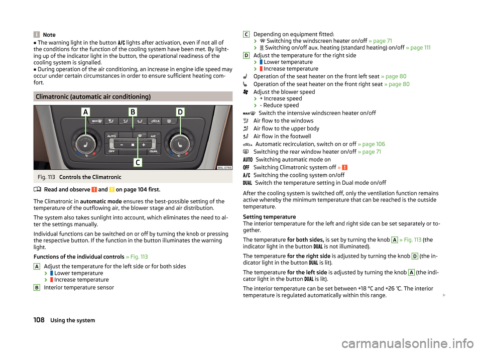
Fig. 113
Controls the Climatronic
Read and observe
and on page 104 first.
The Climatronic in automatic mode ensures the best-possible setting of the
temperature of the outflowing air, the blower stage and air distribution.
The system also takes sunlight into account, which eliminates the need to al-
ter the settings manually.
Individual functions can be switched on or off by turning the knob or pressing
the respective button. If the function in the button illuminates the warning
light.
Functions of the individual controls » Fig. 113
Adjust the temperature for the left side or for both sides
›
Lower temperature
›
Increase temperature
Interior temperature sensor
ABDepending on equipment fitted:
›
Switching the windscreen heater on/off » page 71
›
Switching on/off aux. heating (standard heating) on/off » page 111
Adjust the temperature for the right side ›
Lower temperature
›
Increase temperature
Operation of the seat heater on the front left seat » page 80
Operation of the seat heater on the front right seat » page 80
Adjust the blower speed › + Increase speed
› - Reduce speed
Switch the intensive windscreen heater on/off
Air flow to the windows
Air flow to the upper body
Air flow in the footwell Automatic recirculation, switch on or off » page 106
Switching the rear window heater on/off » page 71
Switching automatic mode on
Switching Climatronic system off »
Switching the cooling system on/off
Switch the temperature setting in Dual mode on/off
After the cooling system is switched off, only the ventilation function remains active whereby the minimum temperature that can be reached is the outside
temperature.
Setting temperature
The interior temperature for the left and right side can be set separately or to-
gether.
The temperature for both sides, is set by turning the knob
A
» Fig. 113 (the
indicator light in the button is not illuminated).
The temperature for the right side is adjusted by turning the knob
D
(the in-
dicator light in the button is lit).
The temperature for the left side is adjusted by turning the knob
A
(the indi-
cator light in the button is lit).
The interior temperature can be set between +18 °C and +26 ℃. The interior
temperature is regulated automatically within this range.
CD108Using the system
Page 116 of 248

Communication and multimedia
General information
Introduction
This chapter contains information on the following subjects:
Validity of the information
113
Mobile phones and two-way radio systems
113
Validity of the information
Fig. 116
Radio Blues / Radio Swing
Fig. 117
Infotainment radio Bolero / Infotainment navigation Amundsen
The functions described in the following sections apply only to vehicles with
Radio Blues » Fig. 116-
or Swing » Fig. 116 -
.
This applies to the following chapters.
› Universal telephone installation kit (hands free)
» page 114
› Universal phone installation kit GSM II
» page 116
› Universal phone installation kit GSM III
» page 118
› WLAN
» page 122
› Voice activation
» page 123
› Multimedia
» page 125
The functions of radio Bolero » Fig. 117-
or Amundsen navigation » Fig. 117-
can be found in the respective infotainment manuals.
Mobile phones and two-way radio systems
ŠKODA permits the operation of mobile phones and two-way radio systems
with a professionally installed external aerial and a maximum transmission
power of up to 10 watts.
Please ask at a specialist workshop about installing and operating mobile
phones and two-way radio systems that have a transmission power of more
than 10 W.
Operating mobile phones or two-way radio systems may interfere with the
functionality of the electronic systems in your vehicle.
The possible reasons for this are: › No external aerial.
› External aerial incorrectly installed.
› transmission power greater than 10 watts.
WARNING■
If a mobile phone or a two-way radio system is operated in a vehicle with-
out an external aerial or an external aerial which has been installed incor-
rectly, this can increase the strength of the electromagnetic field inside the
vehicle.■
Do not attach objects such as mobile telephone holders, etc. to the cov-
ers of the airbag modules or within their immediate vicinity.
■
Never leave a telephone in the deployment area of an airbag, on a seat,
on the dash panel or in another area from which it can be thrown during a
sudden braking manoeuvre, an accident or a collision - risk of injury.
■
Before transport of the vehicle by air, the Bluetooth ®
function must be
switched off by a specialist company.
113Communication and multimedia
Page 117 of 248

Universal telephone preinstallation (hands free)
Introduction
This chapter applies only to vehicles with universal phone installation kit GSM II or GSM III.
This chapter contains information on the following subjects:
Operating the phone on the multifunction steering wheel
114
Symbols in the MAXI DOT display
115
Phone Phonebook
116WARNING■ Concentrate fully at all times on your driving! As the driver you are fully
responsible for the operation of your vehicle. Only use the hands-free sys-
tem to the extent that you are in full control of your vehicle in any traffic
situation.■
The national regulations for using a mobile phone in a vehicle must be
observed.
CAUTION
■ In areas with no signal and sometimes in tunnels, garages or subways tele-
phone conversations can be interrupted and telephone connections cannot be
established - even in an emergency!■
We recommend that the installation of mobile phones and two-way radio
systems in a vehicle be carried out by a specialist garage.
Note■ Not all mobile phones that enable Bluetooth ®
communication are compatible
with the universal telephone preinstallation GSM II or GSM III. Ask a ŠKODA
partner or visit the ŠKODA website www.infotainment.skoda-auto.com to find
out whether your phone is compatible with universal telephone installation kit
GSM II or GSM III.■
The range of the telephone connection to the device using the Bluetooth ®
profile is limited to the vehicle interior. The range is dependent on local fac-
tors, e.g. obstacles between the devices and mutual interferences with other
devices. If your telephone is in a jacket pocket, for example, this can lead to
difficulties when establishing a connection with the device or transferring da-
ta.
■
The functionality of the telephone is dependent on the telephone service op-
erator and the telephone being used. Further information is available from the
telephone service operator or can be found in the telephone manual.
■
In some countries the connection via the Bluetooth ®
function, may be limi-
ted. Further information can be obtained from local authorities.
Operating the phone on the multifunction steering wheel
Fig. 118
Multifunction steering wheel: Control buttons for the telephone
Read and observe and on page 114 first.
There are buttons in the steering wheel for easy operation of the basic func- tions of the phone » Fig. 118 so that the driver is distracted from the traffic as
little as possible when using the phone.
This applies only if your vehicle has been equipped with the universal tele-
phone preinstallation at the factory.
The buttons operate the functions for the operating mode of the current tele-
phone.
If the side lights are switched on, the buttons on the multifunction steering
wheel are illuminated.
114Using the system
Page 131 of 248
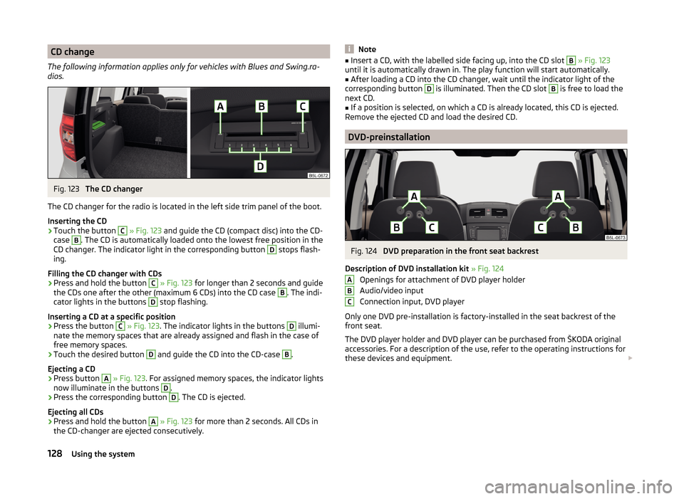
CD change
The following information applies only for vehicles with Blues and Swing.ra-
dios.Fig. 123
The CD changer
The CD changer for the radio is located in the left side trim panel of the boot.
Inserting the CD
›
Touch the button
C
» Fig. 123 and guide the CD (compact disc) into the CD-
case
B
. The CD is automatically loaded onto the lowest free position in the
CD changer. The indicator light in the corresponding button
D
stops flash-
ing.
Filling the CD changer with CDs
›
Press and hold the button
C
» Fig. 123 for longer than 2 seconds and guide
the CDs one after the other (maximum 6 CDs) into the CD case
B
. The indi-
cator lights in the buttons
D
stop flashing.
Inserting a CD at a specific position
›
Press the button
C
» Fig. 123 . The indicator lights in the buttons
D
illumi-
nate the memory spaces that are already assigned and flash in the case of
free memory spaces.
›
Touch the desired button
D
and guide the CD into the CD-case
B
.
Ejecting a CD
›
Press button
A
» Fig. 123 . For assigned memory spaces, the indicator lights
now illuminate in the buttons
D
.
›
Press the corresponding button
D
. The CD is ejected.
Ejecting all CDs
›
Press and hold the button
A
» Fig. 123 for more than 2 seconds. All CDs in
the CD-changer are ejected consecutively.
Note■ Insert a CD, with the labelled side facing up, into the CD slot B » Fig. 123
until it is automatically drawn in. The play function will start automatically.■
After loading a CD into the CD changer, wait until the indicator light of the
corresponding button
D
is illuminated. Then the CD slot
B
is free to load the
next CD.
■
If a position is selected, on which a CD is already located, this CD is ejected.
Remove the ejected CD and load the desired CD.
DVD-preinstallation
Fig. 124
DVD preparation in the front seat backrest
Description of DVD installation kit » Fig. 124
Openings for attachment of DVD player holder
Audio/video input
Connection input, DVD player
Only one DVD pre-installation is factory-installed in the seat backrest of the
front seat.
The DVD player holder and DVD player can be purchased from ŠKODA original
accessories. For a description of the use, refer to the operating instructions for
these devices and equipment.
ABC128Using the system
Page 141 of 248
In the driver's footwell, only a format may be used, which is attached to the
two corresponding attachment points.
Only use factory-supplied foot mats or foot mats from the range of
ŠKODAOriginal Accessories, which are fitted to two attachment points.WARNINGNo objects may be placed in the driver's footwell – risk due to obstruction
or limitation of pedal operation.
Automatic transmission
Introduction
This chapter contains information on the following subjects:
Modes and use of selector lever
138
Selector lever lock
139
Manual shifting of gears (Tiptronic)
139
Starting-off and driving
140
The automatic transmission performs automatic gear changes.
The modes of the automatic transmission can be adjusted by the driver by
means of the selector lever.
WARNING■ No throttle when it is set before starting the mode for moving forward
with the selector lever - there is a risk of accident!■
Never move the selector lever to mode R or P when driving – risk of an
accident!
■
When the vehicle is stationery and the engine is running, you need to
hold the vehicle with the brake pedal in mode D, S or R. Even when the en-
gine is idling, the power transmission is never completely interrupted – the
vehicle creeps.
■
When leaving the vehicle, the selector lever is always to put in the P
mode. Otherwise the vehicle could then start to move and potentially cause
an accident.
CAUTION■ If the selector lever is moved to mode N while driving, the accelerator pedal
must be released and you will need to wait until the engine has reached its
idling speed before moving the selector lever to a forward driving mode again.■
When the outdoor temperature is below -10 ° C, the selector lever when
starting must always be in P mode.
■
When stopping on a slope, never try to hold the vehicle using the accelerator
pedal – this may lead to gear damage.
Note
After the ignition is switched off, the ignition key can only be withdrawn if the
selector lever is in the position P.
Modes and use of selector lever
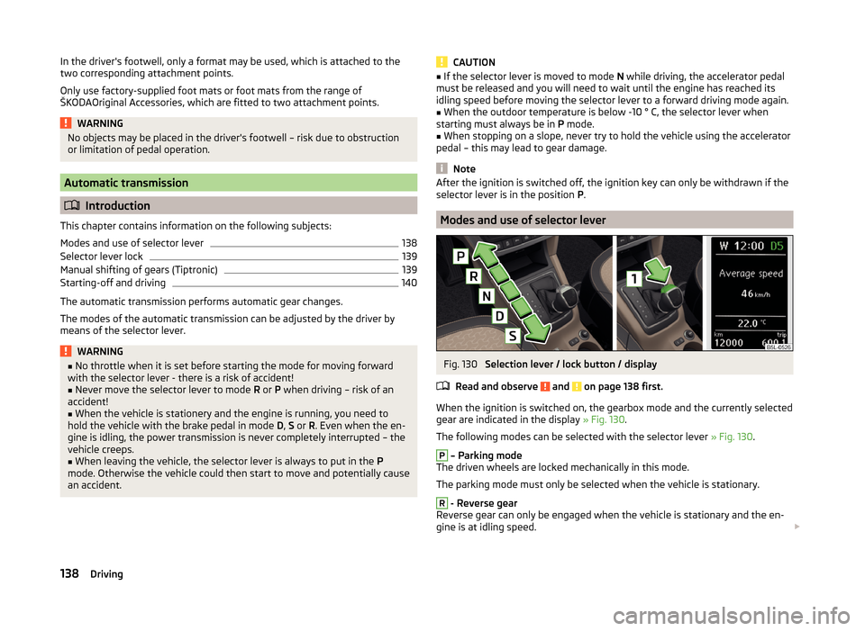
Fig. 130
Selection lever / lock button / display
Read and observe
and on page 138 first.
When the ignition is switched on, the gearbox mode and the currently selected
gear are indicated in the display » Fig. 130.
The following modes can be selected with the selector lever » Fig. 130.
P
– Parking mode
The driven wheels are locked mechanically in this mode.
The parking mode must only be selected when the vehicle is stationary.
R
- Reverse gear
Reverse gear can only be engaged when the vehicle is stationary and the en-
gine is at idling speed.
138Driving
Page 143 of 248
Note■It may be beneficial, for example, when travelling downhill, to use manual
shifting of gears. Shifting to a lower gear reduces the load on the brakes and
hence the wear of the brakes » page 135, Information on braking .■
When accelerating, the gearbox automatically shifts up into the higher gear
just before the maximum permissible engine speed is reached.
■
If a lower gear is selected, the gearbox does not shift down until there is no
risk of the engine overrevving.
Starting-off and driving
Read and observe
and on page 138 first.
Starting off
›
Start the engine.
›
Firmly depress and hold the brake pedal.
›
Press the lock button in the direction of
1
» Fig. 130 on page 138 and hold.
›
Move the selector lever into the desired position » page 138 and then release
the lock button.
›
Release the brake pedal and accelerate.
Stopping (while the car is moving)
›
Depress the brake pedal and bring the vehicle to a stop.
›
Keep holding the brake pedal until driving is resumed.
The selector lever position N does not have to be selected when stopping for a
short time, such as at a cross roads.
Kickdown
The kickdown function allows you to achieve the maximum acceleration of
your vehicle while driving.
When the accelerator pedal is fully depressed, the kickdown function is activa-
ted in any forward driving mode.
The gearbox shifts down one or more gears depending on the vehicle speed
and engine speed, and the vehicle accelerates.
The gearbox does not shift up into the highest gear until the engine has
reached its maximum revolutions for this gear range.
WARNINGRapid acceleration, particularly on slippery roads, can lead to loss of control
of the vehicle – risk of accident!Running in and economical driving
Introduction
This chapter contains information on the following subjects:
Driving in
140
Tips for economical driving
140
The fuel consumption, degree of pollution and vehicle wear depend on driving
style, road condition, weather conditions and the like.
Driving in
Driving in the engine
The engine has to be run in during the first 1 500 kilometres. During this peri-
od, the driving style decides on the quality of the driving-in process.
During the first 1 000 km we recommend not driving faster than 3/4 of the
maximum permissible engine speed, not to drive at full throttle and to dis-
pense with the trailer.
In the area of 1,000 to 1,500 kilometres the engine load can be increased up
to the maximum permitted engine speed.
New tyres
New tyres must firstly be “run in”, as they do not offer optimal grip at first.
Therefore, drive especially carefully for the first 500 km or so.
New brake pads
New brake pads have to first “grind in” because these do not initially have the
best possible braking effect.
Therefore, drive especially carefully for the first 200 km or so.
Tips for economical driving
To achieve the lowest possible fuel consumption, the following instructions
must be observed.
Looking ahead when driving
Avoid unnecessary acceleration and braking.
Switch in an energy saving and timely manner Observe the recommended gear » page 43.
140Driving
Page 145 of 248
Driving off paved roadsRead and observe
on page 141 first.
Only drive on such roads and in such terrain, which match the vehicle parame-ters » page 222 , Technical data as well as your driving skills.
The driver is always responsible for deciding whether the vehicle can handle
travelling in the given terrain.
When travelling off paved roads, we recommend activating the OFF ROAD
mode » page 144 .
WARNINGDrive particularly aware and pro-actively outside paved roads.■Always adjust your driving to the current terrain and weather conditions.
Excessive speed or incorrect driving manoeuvres can cause damage to the
vehicle and lead to serious injuries.■
Objects trapped under the floor of the vehicle can damage the fuel lines,
the brake system, the seals and other parts of the chassis. Check the un-
derside of the vehicle and remove the trapped objects.
■
Combustible objects such as dry leaves or twigs caught under the base of
the vehicle could ignite on hot vehicle parts - risk of fire!
CAUTION
■ Pay attention to the ground clearance of the vehicle! When driving over ob-
jects which are larger than the ground clearance, the chassis and its compo-
nents can get damaged.■
Drive slowly in unknown terrain and watch out for unexpected obstacles,
such as potholes, rocks, stumps, etc.
■
Check up on confusing sections of unpaved roads before travelling on them
and consider whether such travelling is possible without risk.
Assist systems
Braking and stabilisation systems
Introduction
This chapter contains information on the following subjects:
Electronic Stability Control (ESC)
143
Antilock Braking System (ABS)
143
Traction Control System (TCS)
143
Electronic Differential Lock (EDL)
143
Driver Steering Recommendation (DSR)
144
Hydraulic Brake Assist (HBA)
144
Hill Hold Control (HHC)
144
Trailer stabilisation (TSA)
144
This chapter deals with the functions of the braking and stabilisation systems,
with the error indicator referred to in chapter » page 34, Warning lights .
The braking and stabilisation systems are automatically activated each time
the ignition is switched on.
WARNING■ A lack of fuel can cause irregular engine running or cause the engine to
shut down. The brake assist systems would then fail to function – risk of
accident!■
The increased safety provided by the brake assist systems must not
tempt you to take safety risks – risk of accident!
■
Adjust the speed and driving style to the current visibility, weather, road
and traffic conditions.
142Driving