ESP SKODA YETI 2014 1.G / 5L Service Manual
[x] Cancel search | Manufacturer: SKODA, Model Year: 2014, Model line: YETI, Model: SKODA YETI 2014 1.G / 5LPages: 248, PDF Size: 29.49 MB
Page 183 of 248
Diesel fuel additives
The diesel fuel in accordance with the prescribed standards meets all the con-
ditions for a smooth running engine. We therefore recommend that no fuel ad-
ditives are used. This can result in considerable damage to parts of the engine
or the exhaust system.
CAUTION
■ Just filling the tank once with diesel fuel that does not comply with the
standard, can cause severe damage to parts of the engine, the fuel and ex-
haust system!■
If a different fuel other than diesel fuel, which complies to the above men-
tioned standards (e.g. petrol) is put into the tank, do not start the engine or
switch on the ignition! Extensive damage to engine parts can occur!
■
Water which has collected in the fuel filter can cause engine faults.
CAUTION
■ The vehicle cannot be operated with biofuel RME, therefore this fuel must
not be refuelled and driven. The use of biofuel RME can cause considerable
damage to parts of the engine or fuel system.■
Do not mix any fuel additives, so-called “flow improvers” (petrol and similar
agents) into the diesel. This can result in considerable damage to parts of the
engine or the exhaust system!
Engine compartment
Introduction
This chapter contains information on the following subjects:
Opening and closing the bonnet
181
Engine compartment overview
182
Radiator fan
182
Windscreen washer system
182WARNINGInjuries or scolding or risks of accident or fire may occur when working in
the engine compartment. For this reason, it is essential to comply with the
warning instructions outlined below and with the general applicable safety
rules. The engine compartment of your car is a hazardous area!WARNINGInstructions before beginning work in the engine compartment■Turn off the engine and withdraw the ignition key.■
Firmly apply the handbrake.
■
For vehicles with manual transmission the lever into the neutral position.
■
On vehicles with automatic transmission, shift the selector lever into the
P position.
■
Allow the engine to cool.
■
Never open the bonnet if you can see steam or coolant escaping from the
engine compartment – risk of scalding! Wait until no more steam or coolant
is escaping.
WARNINGInformation for working in the engine room■Keep all people, especially children, away from the engine compartment.■
Never touch the radiator fan while the engine is still warm. The fan might
suddenly start running!
■
Do not touch any hot engine parts – risk of burns!
WARNINGInformation for working in the engine compartment with the engine run-
ning■
Pay particular attention to moving engine parts, e.g. V-ribbed belt, gener-
ator, radiator fan - danger to life!
■
Never touch the electric wiring on the ignition system.
■
Avoid short circuits in the electrical system - particularly on the vehicle's
battery.
■
Always make sure that no jewellery, loose clothing or long hair can get
caught in rotating engine parts – risk to life! Always remove any jewellery,
tie back long hair and wear tight fitting clothing before completing any
work.
WARNINGInformation for working on the fuel system or the electrical system■Always disconnect the vehicle battery from the electrical system.■
Do not smoke.
■
Never work near open flames.
■
Always have a functioning fire extinguisher nearby.
180General Maintenance
Page 187 of 248
CAUTION■If the above engine oils are not available, a different engine oil can be used in
an emergency. To prevent damage to the engine, a maximum of 0.5 litres only
of the following engine oils may be used: ■ For petrol engine models: ACEA A3/ACEA B4 or API SN, (API SM);
■ For diesel engine models: ACEA C3 or API CJ-4.
Checking the oil level
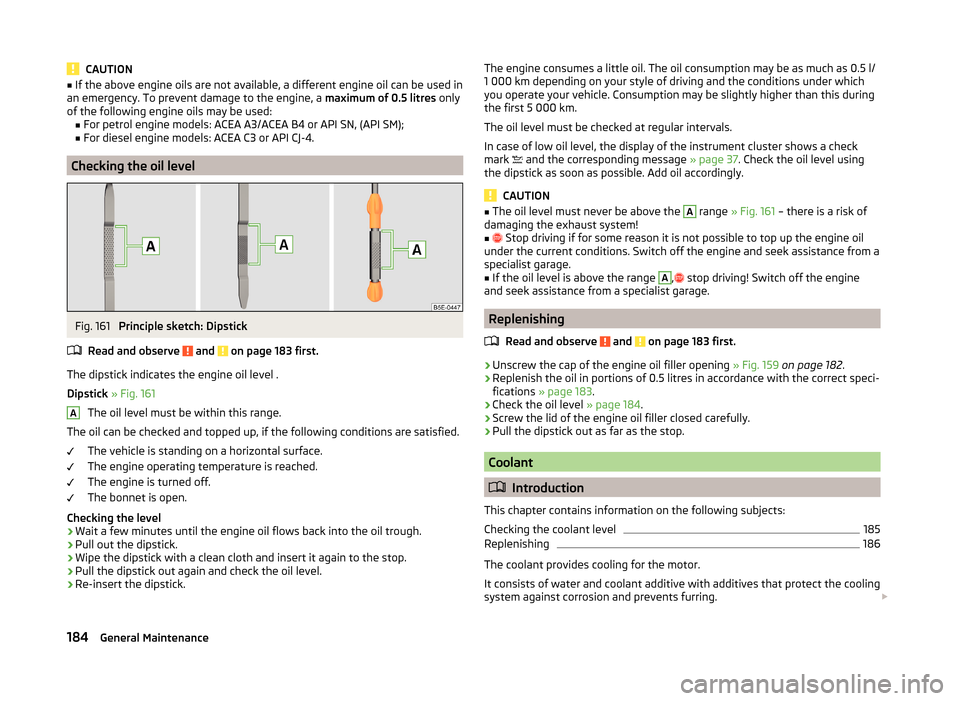
Fig. 161
Principle sketch: Dipstick
Read and observe
and on page 183 first.
The dipstick indicates the engine oil level .
Dipstick » Fig. 161
The oil level must be within this range.
The oil can be checked and topped up, if the following conditions are satisfied. The vehicle is standing on a horizontal surface.
The engine operating temperature is reached.
The engine is turned off.
The bonnet is open.
Checking the level
›
Wait a few minutes until the engine oil flows back into the oil trough.
›
Pull out the dipstick.
›
Wipe the dipstick with a clean cloth and insert it again to the stop.
›
Pull the dipstick out again and check the oil level.
›
Re-insert the dipstick.
AThe engine consumes a little oil. The oil consumption may be as much as 0.5 l/
1 000 km depending on your style of driving and the conditions under which
you operate your vehicle. Consumption may be slightly higher than this during
the first 5 000 km.
The oil level must be checked at regular intervals.
In case of low oil level, the display of the instrument cluster shows a check
mark
and the corresponding message » page 37. Check the oil level using
the dipstick as soon as possible. Add oil accordingly.
CAUTION
■ The oil level must never be above the A range » Fig. 161 – there is a risk of
damaging the exhaust system!■
Stop driving if for some reason it is not possible to top up the engine oil
under the current conditions. Switch off the engine and seek assistance from a
specialist garage.
■
If the oil level is above the range
A
,
stop driving! Switch off the engine
and seek assistance from a specialist garage.
Replenishing
Read and observe
and on page 183 first.
›
Unscrew the cap of the engine oil filler opening » Fig. 159 on page 182 .
›
Replenish the oil in portions of 0.5 litres in accordance with the correct speci-
fications » page 183 .
›
Check the oil level » page 184.
›
Screw the lid of the engine oil filler closed carefully.
›
Pull the dipstick out as far as the stop.
Coolant
Introduction
This chapter contains information on the following subjects:
Checking the coolant level
185
Replenishing
186
The coolant provides cooling for the motor.
It consists of water and coolant additive with additives that protect the cooling
system against corrosion and prevents furring.
184General Maintenance
Page 188 of 248
The coolant additive content in the coolant must be at least 40%.
The coolant additive may be increased to a maximum of 60%.
The correct mixing ratio of water and coolant additive is to be checked if nec- essary by a specialist garage or is to be restored if necessary.
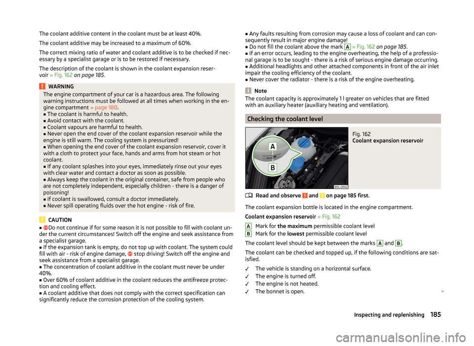
The description of the coolant is shown in the coolant expansion reser-
voir » Fig. 162 on page 185 .WARNINGThe engine compartment of your car is a hazardous area. The following
warning instructions must be followed at all times when working in the en-
gine compartment » page 180.■
The coolant is harmful to health.
■
Avoid contact with the coolant.
■
Coolant vapours are harmful to health.
■
Never open the end cover of the coolant expansion reservoir while the
engine is still warm. The cooling system is pressurized!
■
When opening the end cover of the coolant expansion reservoir, cover it
with a cloth to protect your face, hands and arms from hot steam or hot
coolant.
■
If any coolant splashes into your eyes, immediately rinse out your eyes
with clear water and contact a doctor as soon as possible.
■
Always keep the coolant in the original container, safe from people who
are not completely independent, especially children - there is a danger of
poisoning!
■
If coolant is swallowed, consult a doctor immediately.
■
Never spill operating fluids over the hot engine - risk of fire.
CAUTION
■ Do not continue if for some reason it is not possible to fill with coolant un-
der the current circumstances! Switch off the engine and seek assistance from
a specialist garage.■
If the expansion tank is empty, do not top up with coolant. The system could
fill with air - risk of engine damage,
stop driving! Switch off the engine and
seek assistance from a specialist garage.
■
The concentration of coolant additive in the coolant must never be under
40%.
■
Over 60% of coolant additive in the coolant reduces the antifreeze protec-
tion and cooling effect.
■
A coolant additive that does not comply with the correct specification can
significantly reduce the corrosion protection of the cooling system.
■ Any faults resulting from corrosion may cause a loss of coolant and can con-
sequently result in major engine damage!■
Do not fill the coolant above the mark
A
» Fig. 162 on page 185 .
■
If an error occurs, leading to the engine overheating, the help of a professio-
nal garage is to be sought - there is a risk of serious engine damage occurring.
■
Additional headlights and other attached components in front of the air inlet
impair the cooling efficiency of the coolant.
■
Never cover the radiator - there is a risk of the engine overheating.
Note
The coolant capacity is approximately 1 l greater on vehicles that are fitted
with an auxiliary heater (auxiliary heating and ventilation).
Checking the coolant level
Fig. 162
Coolant expansion reservoir
Read and observe and on page 185 first.
The coolant expansion bottle is located in the engine compartment.
Coolant expansion reservoir » Fig. 162
Mark for the maximum permissible coolant level
Mark for the lowest permissible coolant level
The coolant level should be kept between the marks
A
and
B
.
The coolant can be checked and topped up, if the following conditions are sat-
isfied.
The vehicle is standing on a horizontal surface.
The engine is turned off.
The engine is not heated.
The bonnet is open.
AB185Inspecting and replenishing
Page 190 of 248
A slight drop in the fluid level results when driving due to normal wear-and-
tear and automatic adjustment of the brake pads.
There may be an indication of a leak in the brake system, however, if the fluid
level drops significantly within a short time or if it drops below the “MIN” mark-
ing.
Too low brake fluid level is indicated by the warning light
being shown on
the display of the instrument cluster as well as the corresponding mes-
sage » page 35 ,
Brake system .
Specification
Read and observe
and on page 186 first.
The brake fluid must comply with the following standards or specifications:› VW 50114;
› FMVSS 116 DOT4.
Vehicle battery
Introduction
This chapter contains information on the following subjects:
Opening the cover
188
Checking the battery electrolyte level
188
Charging
189
Replacing
190
Disconnecting and reconnecting
190
Automatic load deactivation
190
The vehicle battery represents a power source for the motor to start and for
the supply of electrical consumers in the car.
Warning symbols on the vehicle battery
SymbolImportanceAlways wear eye protection.Battery acid is severely caustic. Always wear gloves and eye pro-
tection.SymbolImportanceKeep fire, sparks, open flames and lit cigarettes well clear of the
vehicle battery.When charging the vehicle battery, a highly explosive gas mixture
is produced.Keep children away from the vehicle battery.WARNINGThere is risk of injuries, poisoning, chemical burns, explosions or fire when
working on the battery and on the electrical system. The general applicable
safety rules and the following warnings must be observed without excep-
tion.■
Keep the vehicle battery away from people who are not completely inde-
pendent, especially children.
■
Do not tilt the battery otherwise battery electrolyte may flow out of the
battery vent openings. Protect your eyes by wearing safety goggles or a
face shield – risk of blindness!
■
Always wear protective gloves, eye and skin protection when handling
the vehicle battery.
■
The battery acid is strongly corrosive and must, therefore, be handled
with the greatest of care.
■
Corrosive fumes in the air irritate the air passages and lead to conjunctivi-
tis and inflammation of the air passages in the lungs.
■
Battery acid corrodes dental enamel and, if it comes into contact with the
skin, causes deep wounds that take a long time to heal.
■
If any battery acid comes into contact with your eyes, rinse the affected
eye immediately with clean water for several minutes and consult a doctor
immediately!
■
Splashes of acid on your skin or clothes should be neutralised as soon as
possible using soap suds and then rinsed with plenty of water.
■
If you swallow battery acid, consult a doctor immediately!
WARNING■ The use of open flames and light should be avoided.■Smoking and radio triggering activities should be avoided.■
Never use a damaged vehicle battery – risk of explosion!
187Inspecting and replenishing
Page 192 of 248
Air bubbles can influence the colour of the indicator. For this reason carefully
knock on the indicator before carrying out the check.
› Black colour - electrolyte level is correct.
› Colourless or light yellow colour - electrolyte level too low, the battery must
be replaced.
Vehicles with a START-STOP system are fitted with a battery control unit for
checking the energy level for recurring engine start.
We recommend that you have the acid level checked regularly by a specialist garage, especially in the following cases.
› High external temperatures.
› Longer day trips.
› After each charge.
Winter time
The vehicle battery only has a proportion of the starting power in lower tem-
peratures. A discharged vehicle battery may already freeze at temperatures
just below 0 °C .
We therefore recommend that you have the battery checked and, if necessary,
recharged by a specialist garage before the start of the winter.
Note
■ The battery acid level is also checked regularly by a specialist garage as part
of the inspection service.■
For technical reasons, on vehicles with the description “AGM”, the electrolyte
level cannot be checked.
Charging
Read and observe
and on page 187 first.
A properly charged vehicle battery is essential for reliably starting the engine.A charging operation can be performed if the following conditions are satis-
fied.
The engine is turned off.
The ignition is switched off.
All consumers are turned off.
The bonnet is open.
“Fast charging” with high currents
›
Disconnect both battery cables (first of all “negative”, then “positive”).
› Attach the terminal clamps of the charger to the battery terminals (red =
“positive”, black = “negative”).›
Plug the mains cable of the charger into the power socket and switch on the
device.
›
After charging has been successful: Switch off the charger and remove the
mains cable from the power socket.
›
Only then disconnect the charger's terminal clamps.
›
Reconnect the cables to the battery (first “positive”, then “negative”).
Charging with low voltages
It is not necessary to disconnect the cables from the battery if you recharge
the vehicle battery, for example from a mini-charger.
Refer to the instructions of the charger manufacturer .
A charging current of 0.1 multiple of the total vehicle battery capacity (or low-
er) must be used until full charging is achieved.
The vent plugs of the vehicle battery should not be opened for charging.
WARNING■ When you charge a battery, hydrogen is released, and a highly explosive
gas mixture is also produced. An explosion can be caused through sparkling
over during unclamping or loosening of the cable plug while the ignition is
on.■
Creating a bridge between the poles on the battery (e.g. with metal ob-
jects - cables) creates a short circuit - risk of damage to the battery, explo-
sion and burning of the battery, jets of acid spurting out.
■
Avoid creating sparks when working with cables and electrical devices.
Strong sparking represents a risk of injury.
■
Before carrying out any work on the electrical system, switch off the en-
gine, the ignition and all electrical consumers and disconnect the negative
terminal
.
■
“Quick-charging” the vehicle battery is dangerous and requires a special
charger and specialist knowledge.
■
We therefore recommend that vehicle batteries be “rapidly charged” by a
specialist garage.
CAUTION
On vehicles with the START / STOP system or additional heating (auxiliary
heating), do not connect the pole terminal of the charger directly to the nega-
tive terminal of the vehicle battery but only to the engine earth » page 206.189Inspecting and replenishing
Page 193 of 248
ReplacingRead and observe
and on page 187 first.
The new vehicle battery must have the same capacity, voltage, current and thesame size as the original Battery. Suitable vehicle battery types can be pur-
chased from a specialist garage.
We recommend having the battery replaced by a specialist garage, where the
new vehicle battery will be installed properly and the original battery will be
disposed of in accordance with national regulations.
Disconnecting and reconnecting
Read and observe
and on page 187 first.
Disconnecting
›
Switch off the ignition.
›
Disconnect the negative terminal first and then the positive
terminal of
the battery.
Connecting
›
Connect the positive terminal first, then the negative
battery terminal.
After disconnecting and re-connecting the vehicle battery, the following func-
tions or devices are partially or completely inoperative.
Function / deviceOperating measureElectrical power windows» page 60Panorama sliding/tilting roof» page 62Sun screen» page 62
Radio or navigation system
Enter code number » Radio
manual , » Infotainment radio
manual or » Infotainment navi-
gation manualTime settings» page 33
CAUTION
■ Disconnect the vehicle battery only with the ignition turned off - there is a
risk of damaging the electrical system of the vehicle.■
Under no circumstances must the battery cables be connected incorrectly –
risk of a cable fire.
Note■ After disconnecting and re-connecting the vehicle battery, we recommend
having the vehicle checked by a specialist to ensure that the full functionality
of all electrical systems is guaranteed.■
The data of the multi-function display will be reset.
Automatic load deactivation
Read and observe
and on page 187 first.
The vehicle voltage control unit automatically prevents the battery from dis-
charging when the battery is put under high levels of strain. This manifests it-
self by the following.
› The idling speed is raised to allow the generator to deliver more electricity to
the electrical system.
› Where necessary, large convenience consumers such as seat heaters and
rear window heaters have their power limited or are shut off completely in
the event of an emergency.
CAUTION
■ Despite such intervention by the vehicle electric system management, the
vehicle battery may be drained. For example, when the ignition is switched on
a long time with the engine turned off or the side or parking lights are turned
on during longer parking.■
Consumers that are supplied via a 12-V power socket can cause the vehicle
battery to discharge when the ignition is switched off.
Note
Driving comfort is not impaired by consumers being deactivated. The driver is
often not aware of it having taken place.190General Maintenance
Page 195 of 248
The tyre pressure for the spare wheel should correspond to the highest pres-
sure specified for your vehicle.
Always check the inflation pressure when the tyres are cold. Do not reduce the
higher pressure of warm tyres.
In vehicles with tyre pressure monitoring, tyre pressure values must be stored
every time the tyre pressure changes » page 158.
With greater additional load, adjust the tyre inflation pressure accordingly.WARNING■ Having the correct tyre inflation pressure is always the driver's responsi-
bility.■
Too low or too high inflation pressure impairs handling.
■
If the inflation pressure is too low, the tyre will have to overcome a higher
rolling resistance. This will cause a significant increase in the temperature
of the tyre, especially at higher speeds. This can result in tread separation
and a tyre blowout.
■
In the event of very fast tyre inflation pressure loss, such as a sudden tyre
failure, an attempt should be made to bring the vehicle carefully to a stop
without sudden steering movements and without any hard braking.
For the sake of the environment
Tyres that are insufficiently inflated increase your fuel consumption.
Note
In some countries, the vehicles have a sticker without pictograms.
Tyre wear
Read and observe
on page 191 first.
Tyre wear depends on the pressure, driving style, and other circumstances.
Attention to the following factors can reduce tyre wear.
Driving style
Fast cornering, sharp acceleration and braking increase the wear of your tyres.
Wheel balance
The wheels of a new vehicle are balanced. When driving, however, there are a
range of factors that may result in an imbalance. This may become apparent by
a “vibration” in the steering. If this is the case, have the wheels checked by a
specialist garage.
Have the wheels likewise rebalanced after replacing the tyres.
Setting the vehicle geometry
Incorrect wheel alignment at the front or rear leads to excess wear on the
tyres and impairs driving safety. With a distinct tyre wear pattern, we recom-
mend that you check the setting of the vehicle geometry in a specialist work-
shop.WARNING■ An incorrect wheel alignment at the front or rear impairs handling.■Unusual vibrations or pulling of the vehicle to one side could be a sign of
tyre damage. If there is any doubt that a wheel is damaged, immediately re-
duce your speed and stop! If no external tyre damage is evident, drive slow-
ly and carefully to the nearest specialist garage to have the vehicle
checked.
Tyre wear indicator and wheel replacement
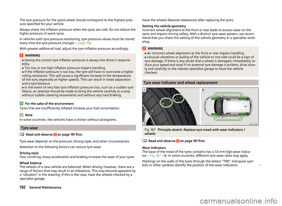
Fig. 167
Principle sketch: Replace tyre tread with wear indicators /
wheels
Read and observe
on page 191 first.
Wear indicators
The base of the tread of the tyres contains has a 1.6 mm high wear indica- tor » Fig. 167 -
. In some countries, different tyre wear rates may apply.
Markings on the walls of the tyres through the letters “TWI”, triangular sym-
bols or other symbols identify the position of the wear indicators.
192General Maintenance
Page 196 of 248
Replacement of wheels
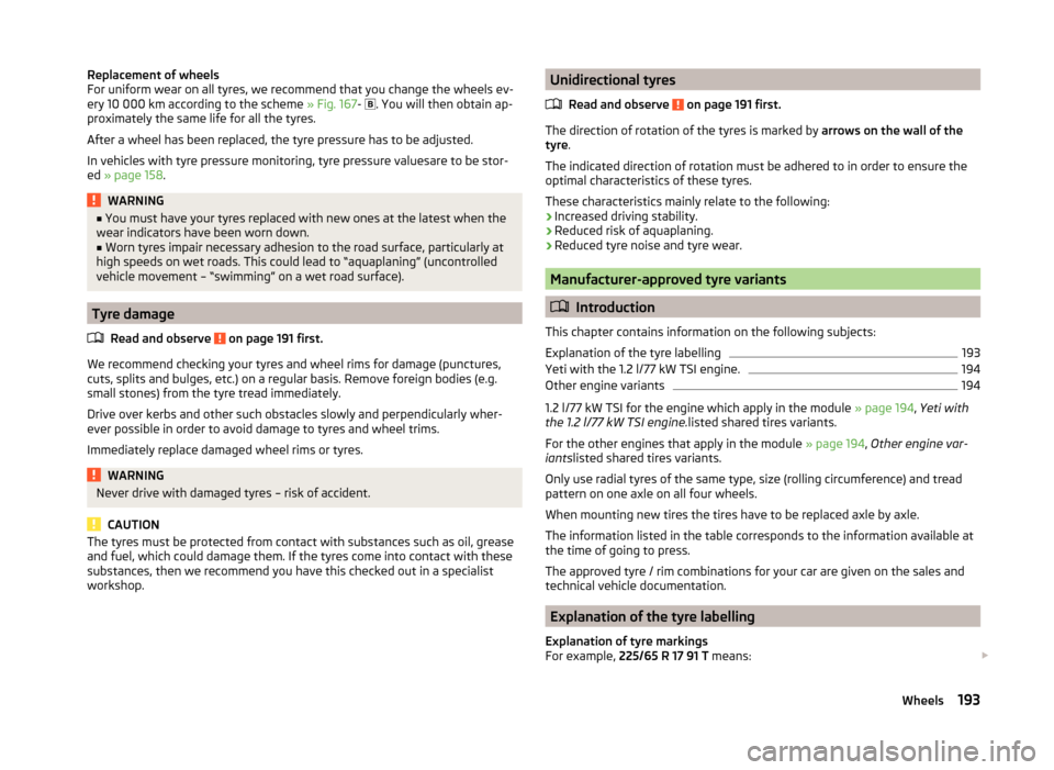
For uniform wear on all tyres, we recommend that you change the wheels ev-
ery 10 000 km according to the scheme » Fig. 167-
. You will then obtain ap-
proximately the same life for all the tyres.
After a wheel has been replaced, the tyre pressure has to be adjusted.
In vehicles with tyre pressure monitoring, tyre pressure valuesare to be stor-
ed » page 158 .WARNING■
You must have your tyres replaced with new ones at the latest when the
wear indicators have been worn down.■
Worn tyres impair necessary adhesion to the road surface, particularly at
high speeds on wet roads. This could lead to “aquaplaning” (uncontrolled vehicle movement – “swimming” on a wet road surface).
Tyre damage
Read and observe
on page 191 first.
We recommend checking your tyres and wheel rims for damage (punctures,
cuts, splits and bulges, etc.) on a regular basis. Remove foreign bodies (e.g.
small stones) from the tyre tread immediately.
Drive over kerbs and other such obstacles slowly and perpendicularly wher-
ever possible in order to avoid damage to tyres and wheel trims.
Immediately replace damaged wheel rims or tyres.
WARNINGNever drive with damaged tyres – risk of accident.
CAUTION
The tyres must be protected from contact with substances such as oil, grease
and fuel, which could damage them. If the tyres come into contact with these
substances, then we recommend you have this checked out in a specialist
workshop.Unidirectional tyres
Read and observe
on page 191 first.
The direction of rotation of the tyres is marked by arrows on the wall of the
tyre .
The indicated direction of rotation must be adhered to in order to ensure the
optimal characteristics of these tyres.
These characteristics mainly relate to the following: › Increased driving stability.
› Reduced risk of aquaplaning.
› Reduced tyre noise and tyre wear.
Manufacturer-approved tyre variants
Introduction
This chapter contains information on the following subjects:
Explanation of the tyre labelling
193
Yeti with the 1.2 l/77 kW TSI engine.
194
Other engine variants
194
1.2 l/77 kW TSI for the engine which apply in the module » page 194, Yeti with
the 1.2 l/77 kW TSI engine. listed shared tires variants.
For the other engines that apply in the module » page 194, Other engine var-
iants listed shared tires variants.
Only use radial tyres of the same type, size (rolling circumference) and tread
pattern on one axle on all four wheels.
When mounting new tires the tires have to be replaced axle by axle.
The information listed in the table corresponds to the information available at the time of going to press.
The approved tyre / rim combinations for your car are given on the sales and
technical vehicle documentation.
Explanation of the tyre labelling
Explanation of tyre markings
For example, 225/65 R 17 91 T means:
193Wheels
Page 198 of 248
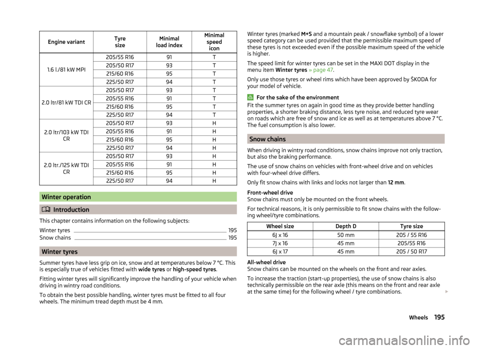
Engine variantTyresizeMinimal
load indexMinimal speed icon
1.6 l./81 kW MPI
205/55 R1691T205/50 R1793T215/60 R1695T225/50 R1794T
2.0 ltr/81 kW TDI CR
205/50 R1793T205/55 R1691T215/60 R1695T225/50 R1794T
2.0 ltr/103 kW TDI CR
205/50 R1793H205/55 R1691H215/60 R1695H225/50 R1794H
2.0 ltr./125 kW TDI CR
205/50 R1793H205/55 R1691H215/60 R1695H225/50 R1794H
Winter operation
Introduction
This chapter contains information on the following subjects:
Winter tyres
195
Snow chains
195
Winter tyres
Summer tyres have less grip on ice, snow and at temperatures below 7 °C. This
is especially true of vehicles fitted with wide tyres or high-speed tyres .
Fitting winter tyres will significantly improve the handling of your vehicle when
driving in wintry road conditions.
To obtain the best possible handling, winter tyres must be fitted to all four
wheels. The minimum tread depth must be 4 mm.
Winter tyres (marked M+S and a mountain peak / snowflake symbol) of a lower
speed category can be used provided that the permissible maximum speed of
these tyres is not exceeded even if the possible maximum speed of the vehicle
is higher.
The speed limit for winter tyres can be set in the MAXI DOT display in the
menu item Winter tyres » page 47 .
Only use those tyres or wheel rims which have been approved by ŠKODA for
your model of vehicle.
For the sake of the environment
Fit the summer tyres on again in good time as they provide better handling
properties, a shorter braking distance, less tyre noise, and reduced tyre wear
on roads which are free of snow and ice as well as at temperatures above 7 °C.
The fuel consumption is also lower.
Snow chains
When driving in wintry road conditions, snow chains improve not only traction,
but also the braking performance.
The use of snow chains on vehicles with front-wheel drive and on vehicles
with four-wheel drive differs.
Only fit snow chains with links and locks not larger than 12 mm.
Front-wheel drive
Snow chains must only be mounted on the front wheels.
For technical reasons, it is only permissible to fit snow chains with the follow-
ing wheel/tyre combinations.
Wheel sizeDepth DTyre size6J x 1650 mm205 / 55 R167J x 1645 mm205/55 R166J x 1745 mm205 / 50 R17
All-wheel drive
Snow chains can be mounted on the wheels on the front and rear axles.
To increase the traction (start-up properties), the use of snow chains is also technically permissible on the rear axle (this means on the front and rear axle
at the same time) for the following wheel / tyre combinations.
195Wheels
Page 211 of 248
›Take the vehicle out of gear or move the selector lever into position
N if the
vehicle is fitted with an automatic gearbox.
Please note that the brake servo unit and power steering only operate if the
engine is running. If the engine is not running, significantly more physical force
is required to depress the brake pedal and steer the vehicle.
If using a tow rope, ensure that it is always kept taught.
Both drivers should be familiar with the problems which might occur while a vehicle is being towed. Unskilled drivers should not attempt to tow in another
vehicle or to be towed in.
The vehicle must be transported on a special breakdown vehicle or trailer if it
is not possible to tow in the vehicle in the way described or if the towing dis-
tance is greater than 50 km.WARNING■ When towing, respect the national legal provisions, especially those
which relate to the identification of the towing vehicle and the vehicle be-
ing towed.■
When towing, exercise increased caution.
■
Do not use spiral rope for towing » Fig. 181-
, the towing eye may un-
screw from the vehicle - risk of accident.
■
Ensure tow rope is not twisted - risk of accident.
CAUTION
■ Do not tow start the engine – there is a risk of damaging the engine and the
catalytic converter. The battery from another vehicle can be used as a jump-
start aid » page 206 , Jump-starting .■
If the gearbox has no oil, your vehicle must be towed with the front axle
raised clear of the ground or on a breakdown vehicle or trailer.
■
To protect both vehicles when tow-starting or towing, the tow rope should
be elastic. Thus one should only use plastic fibre rope or a rope made out of a
similarly elastic material.
■
There is always a risk of excessive stresses and damage resulting at the
points to which you attach the tow rope or tow bar when you attempt to tow a
vehicle which is not standing on a paved road.
■
Attach the tow rope or the tow bar to the towing eyes » page 208
or » page 209 to the detachable ball head of the towing device » page 159 .
NoteWe recommend using a tow rope from ŠKODA Original Accessories, which is
available from a ŠKODA Partner.
Front towing eye
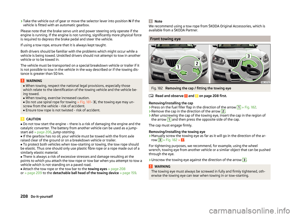
Fig. 182
Removing the cap / fitting the towing eye
Read and observe
and on page 208 first.
Removing/installing the cap
›
Press on the fuel filler flap in the direction of the arrow
1
» Fig. 182 .
›
Remove the cap in the direction of the arrow
2
.
›
After unscrewing the cap of the towing eye, insert the cap in the region of
the arrow
1
and then press the opposite side of the cap.
The cap must engage firmly.
Removing/installing the towing eye
›
Manually screw the towing eye as far as it will go in the direction of the ar-
row
3
» Fig. 182 » .
For tightening purposes, we recommend, for example, using the wheel
wrench, towing eye from another vehicle or a similar object that can be pushed through the eye.
›
Unscrew the towing eye against the direction of the arrow
3
.
WARNINGThe towing eye must always be screwed in fully and firmly tightened, oth-
erwise the towing eye can tear when towing in or tow-starting.208Do-it-yourself