coolant SSANGYONG KORANDO 1997 Service Owners Manual
[x] Cancel search | Manufacturer: SSANGYONG, Model Year: 1997, Model line: KORANDO, Model: SSANGYONG KORANDO 1997Pages: 2053, PDF Size: 88.33 MB
Page 743 of 2053

1D3 -- 8 OM600 ENGINE COOLING
D AEW OO M Y_2000
WATER PUMP HOUSING
Preceding Work : Removal of water pump
Removal of thermostat
Removal of generator
1 Gasket Replace..........................
2 Water Pump Housing
3 Connector
4Bolt 10N∙m (89 lb-in) .....................5 Coolant Hose
6ReturnPipe
7 O -- Ring
8 Temperature Sensor
Notice
The bolt on the arrow should be installed last.
Page 744 of 2053
OM600 ENGINE COOLING 1D3 -- 9
D AEW OO M Y_2000
Removal & Installation Procedure
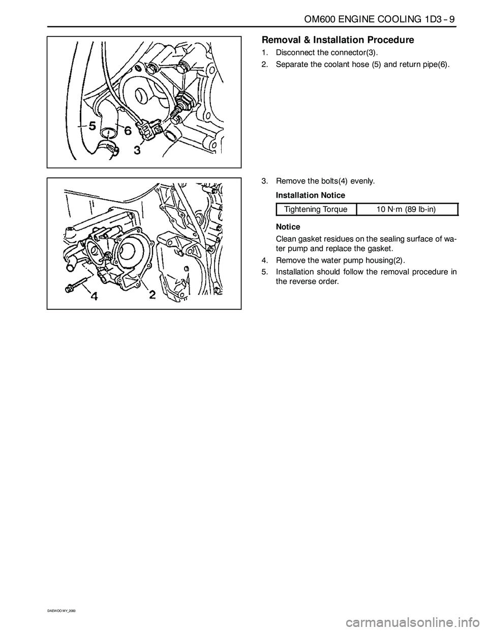
1. Disconnect the connector(3).
2. Separate the coolant hose (5) and return pipe(6).
3. Remove the bolts(4) evenly.
Installation Notice
Tightening Torque10 N∙m(89lb-in)
Notice
Clean gasket residues on the sealing surface of wa-
ter pump and replace the gasket.
4. Remove the water pump housing(2).
5. Installation should follow the removal procedure in
the reverse order.
Page 748 of 2053
OM600 ENGINE COOLING 1D3 -- 13
D AEW OO M Y_2000
Removal & Installation Procedure
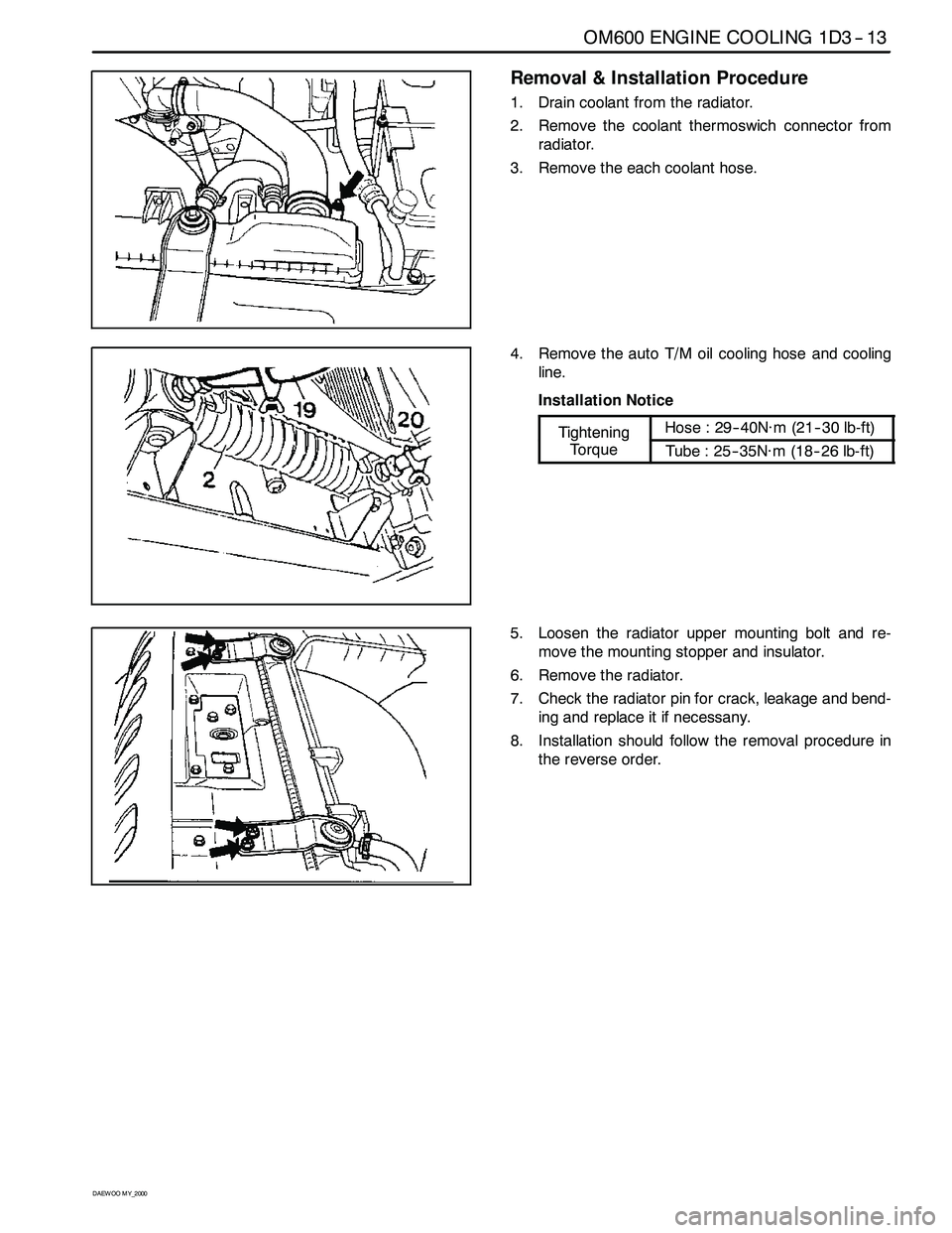
1. Drain coolant from the radiator.
2. Remove the coolant thermoswich connector from
radiator.
3. Remove the each coolant hose.
4. Remove the auto T/M oil cooling hose and cooling
line.
Installation Notice
TighteningHose : 29-- 40N∙m (21-- 30 lb-ft)Tightening
TorqueTube : 25-- 35N∙m (18--26 lb-ft)
5. Loosen the radiator upper mounting bolt and re-
move the mounting stopper and insulator.
6. Remove the radiator.
7. Check the radiator pin for crack, leakage and bend-
ing and replace it if necessany.
8. Installation should follow the removal procedure in
the reverse order.
Page 750 of 2053
OM600 ENGINE COOLING 1D3 -- 15
D AEW OO M Y_2000
Removal & Installation Procedure
Cooling Fan Shroud
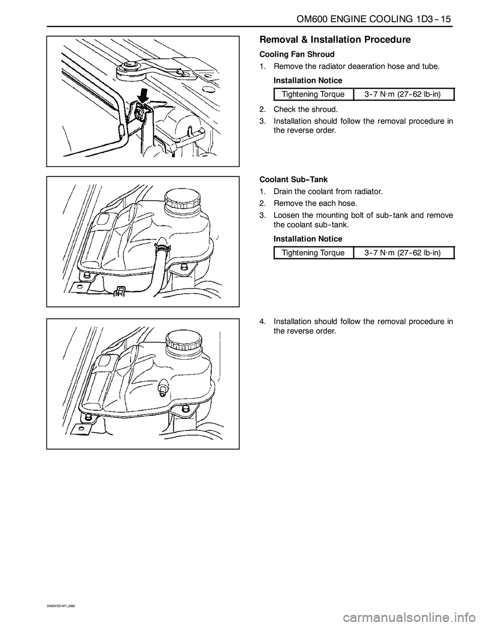
1. Remove the radiator deaeration hose and tube.
Installation Notice
Tightening Torque3--7 N∙m (27-- 62 lb-in)
2. Check the shroud.
3. Installation should follow the removal procedure in
the reverse order.
Coolant Sub-- Tank
1. Drain the coolant from radiator.
2. Remove the each hose.
3. Loosen the mounting bolt of sub-- tank and remove
the coolant sub-- tank.
Installation Notice
Tightening Torque3--7 N∙m (27-- 62 lb-in)
4. Installation should follow the removal procedure in
the reverse order.
Page 751 of 2053
1D3 -- 16 OM600 ENGINE COOLING
D AEW OO M Y_2000
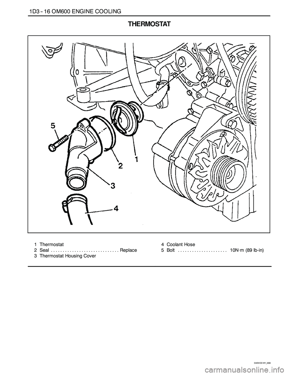
THERMOSTAT
1 Thermostat
2 Seal Replace.............................
3 Thermostat Housing Cover4 Coolant Hose
5 Bolt 10N∙m(89lb-in) .....................
Page 752 of 2053
OM600 ENGINE COOLING 1D3 -- 17
D AEW OO M Y_2000
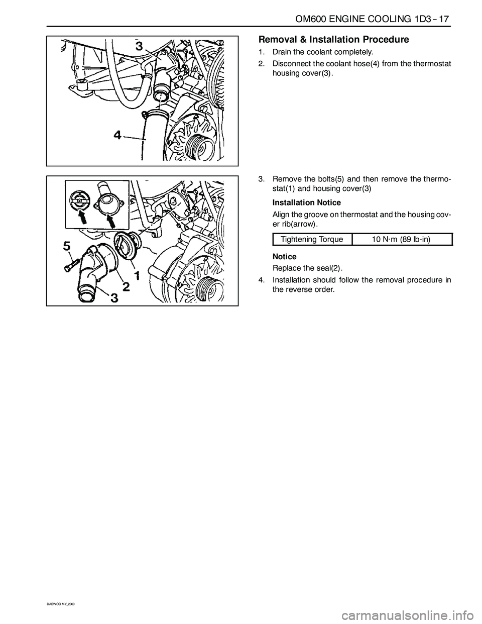
Removal & Installation Procedure
1. Drain the coolant completely.
2. Disconnect the coolant hose(4) from the thermostat
housing cover(3).
3. Remove the bolts(5) and then remove the thermo-
stat(1) and housing cover(3)
Installation Notice
Align the groove on thermostat and the housing cov-
er rib(arrow).
Tightening Torque10 N∙m(89lb-in)
Notice
Replace the seal(2).
4. Installation should follow the removal procedure in
the reverse order.
Page 772 of 2053
OM600 ENGINE CONTROLS 1F3 -- 15
D AEW OO M Y_2000
IDLE SPEED ADJUSTMENT
Service Data
EngineIdle Speed
OM661LA Engine750 -- 850 rpm
OM662LA Engine720 -- 820 rpm
Tools Required
667 589 00 21 00 TDC Pulse Generato
Commercial Tool
Digital Testere.g. Bosch, MOT 001.03g
Sun, DIT 9000
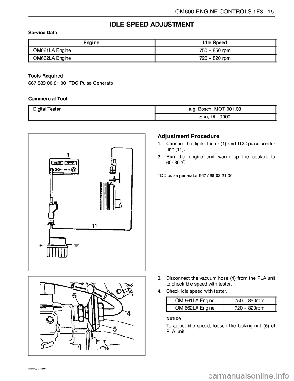
Adjustment Procedure
1. Connect the digital tester (1) and TDC pulse sender
unit (11).
2. Run the engine and warm up the coolant to
60~80_C.
TDC pulse generator 667 589 02 21 00
3. Disconnect the vacuum hose (4) from the PLA unit
to check idle speed with tester.
4. Check idle speed with tester.
OM 661LA Engine750 -- 850rpm
OM 662LA Engine720 -- 820rpm
Notice
To adjust idle speed, loosen the locking nut (6) of
PLA unit.
Page 810 of 2053
OM600 ENGINE CONTROLS 1F3 -- 7
D AEW OO M Y_2000
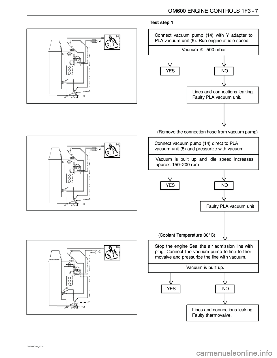
Test step 1
Connect vacuum pump (14) with Y adapter to
PLA vacuum unit (5). Run engine at idle speed.
Vacuum≧500 mbar
YES
NO
Faulty PLA vacuum unit
(Coolant Temperature 30_C)
Connect vacuum pump (14) direct to PLA
vacuum unit (5) and pressurize with vacuum.
YES
NO
Lines and connections leaking.
Faulty PLA vacuum unit.
(Remove the connection hose from vacuum pump)
Vacuum is built up and idle speed increases
approx. 150-- 200 rpm
YESNO
Lines and connections leaking.
Faulty thermovalve.
Stop the engine Seal the air admission line with
plug. Connect the vacuum pump to line to ther-
movalve and pressurize the line with vacuum.
Vacuum is built up.
Page 1134 of 2053
5A-40 AUTOMATIC TRANSMISSION
SSANGYONG MY2002
Dye and Black Light Method
1. Add dye to the transmission through the transmission
fluid filler plug. Follow the manufacturer’s recommen-
dation for the amount of dye to be used.
2. Use the black light to find the fluid leak.
3. Make the necessary repairs.
Repairing the Fluid Leak
Once the leak point is found the source of the leak
must be determined. The following list describes the
potential causes for the leak:
Fasteners are not torqued to specification.
Fastener threads and fastener holes are dirty or
corroded.
Gaskets, seals or sleeves are misaligned, damaged
or worn.
Damaged, warped or scratched seal bore or gasket
surface.
Loose or worn bearing causing excess seal or sleeve
wear.
Case or component porosity.
Fluid level is too high.
Plugged vent or damaged vent tube.
Water or coolant in fluid.
Fluid drain back holes plugged.
ELECTRICAL / GARAGE SHIFT
TEST
This preliminary test should be performed before a hoist
or road test to make sure electronic control inputs are
connected and operating. If the inputs are not checked
before operating the transmission, a simple electrical
condition could be misdiagnosed as a major
transmission condition.
A scan tool provides valuable information and must
be used on the automatic transmission for accurate
diagnosis.
1. Move gear shift control lever to P (Park) and set
the parking brake.
2. Connect scan tool to Data Link Connector (DLC)
terminal.
3. Start engine.
4. Turn the scan tool ON.
5. Verify that the appropriate signals are present.
These signals may include:
ENGINE SPEED
VEHICLE SPEED
THROTTLE POSITION
ACCEL. PEDAL POSITION
TRANSMISSION GEAR STATE
GEAR SHIFT LEVER POSITION
TRANSMISSION FLUID TEMPERATURE
CLOSED THROTTLE POSITION LEARN
OPEN THROTTLE POSITION LEARNT
CLOSED ACCEL. PEDAL POSITION LEARNT
OPEN ACCEL. PEDAL POSITION LEARNT
A/C COMPRESSOR STATUS
KICKDOWN SWITCH STATUS
4WD STATUS
MODE SWITCH
THROTTLE POSITION VOLTAGE
GEAR SHIFT LEVER POSITION VOLTAGE
TRANS. FLUID TEMPERATURE VOLTAGE
A/C SWITCH
KICKDOWN SWITCH VOLTAGE
4WD LAMP LOW VOLTAGE
4WD LAMP HIGH VOLTAGE
MODE SWITCH VOLTAGE
BATTERY VOLTAGE
6. Monitor the A/C COMPRESSOR STATUS signal
while pushing the A/C switch.
The A/C COMPRESSOR STATUS should come
ON when the A/C switch is pressed, and turn
OFF when the A/C switch is repushed.
7. Monitor the GEAR SHIFT LEVER POSITION signal
and move the gear shift control lever through all
the ranges.
Verify that the GEAR SHIFT LEVER POSITION
value matches the gear range indicated on the
instrument panel or console.
Gear selections should be immediate and not
harsh.
8. Move gear shift control lever to neutral and monitor
the THROTTLE POSITION signal while increasing
and decreasing engine speed with the accelerator
pedal.
THROTTLE POSITION should increase with en-
gine speed.
ROAD TEST PROCEDURE
Perform the road test using a scan tool.
This test should be performed when traffic and road
conditions permit.
Observe all traffic regulations.
ELECTRONIC ADJUSTMENTS
Idle Speed Adjustments
Carry out the adjustments to the idle speed as detailed
in the workshop manual.
Vehicle Coding
The vehicle coding is integrated as part of the
diagnostic software. A scan tool has the function to
code the ve-hicle through the K-line.
Page 1135 of 2053
5A-40 AUTOMATIC TRANSMISSION
SSANGYONG MY2002
Dye and Black Light Method
1. Add dye to the transmission through the transmission
fluid filler plug. Follow the manufacturer’s recommen-
dation for the amount of dye to be used.
2. Use the black light to find the fluid leak.
3. Make the necessary repairs.
Repairing the Fluid Leak
Once the leak point is found the source of the leak
must be determined. The following list describes the
potential causes for the leak:
Fasteners are not torqued to specification.
Fastener threads and fastener holes are dirty or
corroded.
Gaskets, seals or sleeves are misaligned, damaged
or worn.
Damaged, warped or scratched seal bore or gasket
surface.
Loose or worn bearing causing excess seal or sleeve
wear.
Case or component porosity.
Fluid level is too high.
Plugged vent or damaged vent tube.
Water or coolant in fluid.
Fluid drain back holes plugged.
ELECTRICAL / GARAGE SHIFT
TEST
This preliminary test should be performed before a hoist
or road test to make sure electronic control inputs are
connected and operating. If the inputs are not checked
before operating the transmission, a simple electrical
condition could be misdiagnosed as a major
transmission condition.
A scan tool provides valuable information and must
be used on the automatic transmission for accurate
diagnosis.
1. Move gear shift control lever to P (Park) and set
the parking brake.
2. Connect scan tool to Data Link Connector (DLC)
terminal.
3. Start engine.
4. Turn the scan tool ON.
5. Verify that the appropriate signals are present.
These signals may include:
ENGINE SPEED
VEHICLE SPEED
THROTTLE POSITION
ACCEL. PEDAL POSITION
TRANSMISSION GEAR STATE
GEAR SHIFT LEVER POSITION
TRANSMISSION FLUID TEMPERATURE
CLOSED THROTTLE POSITION LEARN
OPEN THROTTLE POSITION LEARNT
CLOSED ACCEL. PEDAL POSITION LEARNT
OPEN ACCEL. PEDAL POSITION LEARNT
A/C COMPRESSOR STATUS
KICKDOWN SWITCH STATUS
4WD STATUS
MODE SWITCH
THROTTLE POSITION VOLTAGE
GEAR SHIFT LEVER POSITION VOLTAGE
TRANS. FLUID TEMPERATURE VOLTAGE
A/C SWITCH
KICKDOWN SWITCH VOLTAGE
4WD LAMP LOW VOLTAGE
4WD LAMP HIGH VOLTAGE
MODE SWITCH VOLTAGE
BATTERY VOLTAGE
6. Monitor the A/C COMPRESSOR STATUS signal
while pushing the A/C switch.
The A/C COMPRESSOR STATUS should come
ON when the A/C switch is pressed, and turn
OFF when the A/C switch is repushed.
7. Monitor the GEAR SHIFT LEVER POSITION signal
and move the gear shift control lever through all
the ranges.
Verify that the GEAR SHIFT LEVER POSITION
value matches the gear range indicated on the
instrument panel or console.
Gear selections should be immediate and not
harsh.
8. Move gear shift control lever to neutral and monitor
the THROTTLE POSITION signal while increasing
and decreasing engine speed with the accelerator
pedal.
THROTTLE POSITION should increase with en-
gine speed.
ROAD TEST PROCEDURE
Perform the road test using a scan tool.
This test should be performed when traffic and road
conditions permit.
Observe all traffic regulations.
ELECTRONIC ADJUSTMENTS
Idle Speed Adjustments
Carry out the adjustments to the idle speed as detailed
in the workshop manual.
Vehicle Coding
The vehicle coding is integrated as part of the
diagnostic software. A scan tool has the function to
code the ve-hicle through the K-line.