head SSANGYONG KORANDO 1997 Service Repair Manual
[x] Cancel search | Manufacturer: SSANGYONG, Model Year: 1997, Model line: KORANDO, Model: SSANGYONG KORANDO 1997Pages: 2053, PDF Size: 88.33 MB
Page 787 of 2053

1F3 -- 30 OM600 ENGINE CONTROLS
D AEW OO M Y_2000
Tools Required
601589000800 Flange
601 589 05 21 00 Locking Screw
116 589 20 33 00 Sliding Hammer
116 589 02 34 00 Threaded Bolt
667 589 04 63 00 Retaining Plate
Removal & Installation Procedure
1. Remove the bolts (2) and then remove the cylinder
head cover (1) and gasket (3).
Installation Notice
Tightening Torque10 N∙m(89lb-in)
Notice
Replace the gasket.
Rotate the engine 1 revolution by hand and check
TDC marking of the crankshaft and camshaft.
2. Loosen the camshaft sprocket bolt (14).
Notice
Do not remove the bolt.
Installation Notice
Tightening Torque25N∙m (18 lb-ft) + 90_
Notice
If max. length of bolt exceeds 53.6mm, replace it.
3. Loosen the bolt (11) (left -- hand thread).
Notice
Do not remove the bolt.
Page 987 of 2053

ABS AND TCS 4F-3
SSANGYONG MY2002
GENERAL DESCRIPTION AND SYSTEM OPERATION
BASIC KNOWLEDGE REQUIRED
Before using this section, it is important that you have
a basic knowledge of the following items. Without this
knowledge, it will be difficult to use the diagnostic
procedures contained in this section.
•Basic Electrical Circuits - You should understand
the basic theory of electricity and know the meaning
of voltage, current (amps), and resistance (ohms).
You should understand what happens in a circuit
with an open or shorted wire. You should be able to
read and understand a wiring diagram.
Use of Circuit Testing Tools - You should know
how to use a test light and how to bypass
components to test circuits using fused jumper
wires. You should be familiar with a digital
multimeter. You should be able to measure voltage,
resistance, and current, and be familiar with the
controls and how to use them correctly.
ABS SYSTEM COMPONENTS
The ABS 5.3 Antilock Braking System (ABS) consists
of a conventional hydraulic brake system plus antilock
components. The conventional brake system includes
a vacuum booster, master cylinder, front disc brakes,
rear disc brakes, interconnecting hydraulic brake pipes
and hoses, brake fluid level switch and the BRAKE
indicator.
The ABS components include a hydraulic unit, an elec-
tronic brake control module (EBCM), two system fuses,
four wheel speed sensors (one at each wheel), intercon-
necting wiring, the ABS indicator, the EBD indicator
and the TCS indicator. See “ABS Component Locator”
in this section for the general layout of this system.
The hydraulic unit with the attached EBCM is located
between the surge tank and the bulkhead on the left
side of the vehicle.
The basic hydraulic unit configuration consists of hy-
draulic check valves, two solenoid valves for each
wheel, a hydraulic pump, and two accumulators. The
hydraulic unit controls hydraulic pressure to the front
calipers and rear calipers by modulating hydraulic
pressure to prevent wheel lockup.
Units equipped with TCS add two more valves for each
drive wheel for the purpose of applying the brake to a
wheel that is slipping. This is done with pressure from
the hydraulic pump in the unit. There is also a TCS
indicator lamp on the instrument panel to alert the driver
to the fact that the TCS system is active. The
components identified in the drawing are those added
to the basic ABS 5.3 system to provide traction control.
Nothing in the hydraulic unit or the EBCM is serviceable.
In the event of any failure, the entire ABS unit withattached EBCM must be replaced. For more
information, refer to “Base Braking Mode” and
“Antilock Braking Mode” in this section.
TRACTION CONTROL SYSTEM
(TCS) DESCRIPTION
General Information
The traction control system (TCS) is a traction system
by means of brake intervention only, available in a low
speed range (< 60kph).
It workes on µ - split roads with sidewise different friction
coefficients.
The spinning driven wheel is braked and the drive
torque can be transferred to the wheel on the high-µ
side. During TCS active, the TCS information lamp is
blinking.
The temperature of the brakes is calculated by a mathe-
matical model and TCS is switched passive if the calcu-
lated temperature is greater than a threshold value (500
°C).
TCS is permitted again, when the calculated tempera-
ture is less than 350 °C.
Control Algorithm
The input signals for the control algorithm are the
filtered wheel speed signals from the ABS speed
processing.
With the speed difference of the driven wheels, the
control deviation is calculated.
If the control deviation exceeds a certain threshold
value, the wheel with the greater slip is braked actively.
The threshold value depends on the vehicle speed:
It is reduced with increasing vehicle speed down to a
constant value.
KAA4F010
Page 1263 of 2053

5A-168 AUTOMATIC TRANSMISSION
SSANGYONG MY2002
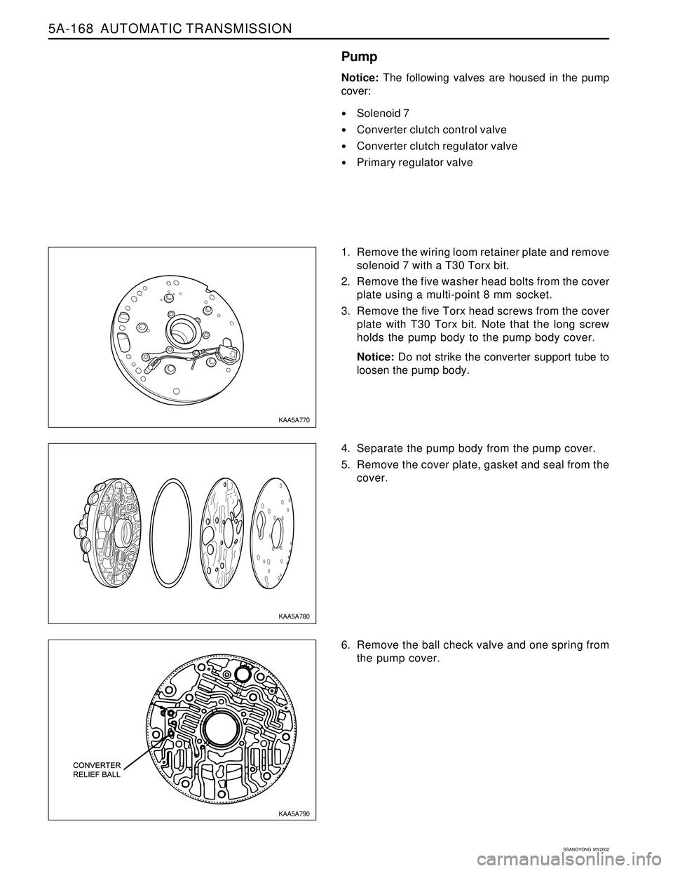
Pump
Notice: The following valves are housed in the pump
cover:
Solenoid 7
Converter clutch control valve
Converter clutch regulator valve
Primary regulator valve
1. Remove the wiring loom retainer plate and remove
solenoid 7 with a T30 Torx bit.
2. Remove the five washer head bolts from the cover
plate using a multi-point 8 mm socket.
3. Remove the five Torx head screws from the cover
plate with T30 Torx bit. Note that the long screw
holds the pump body to the pump body cover.
Notice: Do not strike the converter support tube to
loosen the pump body.
4. Separate the pump body from the pump cover.
5. Remove the cover plate, gasket and seal from the
cover.
6. Remove the ball check valve and one spring from
the pump cover.
KAA5A790 KAA5A780 KAA5A770
Page 1330 of 2053

SSANGYONG MY2002
5B-22 MANUAL TRANSMISSION
62 - 93 Nm
(45 - 69 lb-ft)
21 - 35 Nm
(15 - 26 lb-ft)
Check the housing face alignment.
- Place the dial indicator on the housing face.
- By rotating the crankshaft one revolution,
record the dial indicator reading.
Notice: If the reading is greater than 0.010 inch,
insert the shim between the engine and clutch
housing and adjust the alignment.
5. Check the following parts :
Pressure plate spring assembly
Disc
Flywheel
Input shaft pilot bearing
Notice: Replace the excessively worn parts.
6. Lubricate the clutch release bearing bore, fork
pivot head during assembly.
Installation Procedure
1. Install the transmission to the vehicle. At this time,
seat correctly the input shaft of the transmission
on the pilot bearing of the flywheel.
2. Tighten the transmission mounting bolts as the
specified torque on the vehicle.
Installation Notice
YAD5B390
YAD5B400
YAD5B410
YAD5B420
Tightening Torque77 - 87 Nm
(57 - 64 lb-ft)
3. Install the cross member and tighten as the
specified torque by supporting the suitable jack.
Installation Notice
Tightening
TorqueLeft/Right
Center
Page 1363 of 2053

SSAMGYONG MY2002
5C-8 CLUTCH
5. Unscrew the bolts and remove the clutch cover,
pressure plate and clutch disc.
Notice: Be careful not to drop the pressure plate
and clutch disc.
Installation Notice
6. Installation should follow the removal procedure
in the reverse order.
Notice:
Before installation, clean oil and grease on the
flywheel surface.
Do not clean the clutch disc and release bearing
in solvent.
2. Clutch Disc
Check the facing for rivet looseness, excessive
runout, sticks, oil and grease.
Measure the rivet head depth.
If out limit, replace the disc.
Inspection Procedure
1. Clutch Cover
Check the diaphragm spring tip for wear and
height unevenness.
Check the pressure plate surface for wear, crack
and discoloration.
Check the strap plate rivet for looseness and
replace the clutch cover if loosened.
KAA5C090
KAA5C100
KAA5C110
Tightening Torque21 - 27 Nm
(15 - 20 lb-ft)
Wear Limit 0.3 mm
Unevenness Limit 0.8 mm
Page 1469 of 2053

SECTION 6C
POWER STEERING GEAR
TABLE OF CONTENTS
Description and Operation...................................6C-2
Power Rack and Pinion........................................6C-2
Component Locator.............................................6C-3
Diagnostic Information and Procedures..............6C-4
Power Steering Rack and Pinion Gear...................6C-4
Power Steering Rack and Pinion Gear Bench
Testing.............................................................6C-6
Straight-Ahead Check ..........................................6C-6
Repair Instructions................................................6C-8
On-Vehicle Service.................................................6C-8
Rack and Pinion Assembly..................................6C-8
Outer Tie Rod......................................................6C-9Dust Boot.......................................................... 6C-10
Intermediate Shaft............................................. 6C-10
Hydraulic Cylinder Lines.................................... 6C-11
Unit Repair.......................................................... 6C-13
Rack and Pinion................................................ 6C-13
Valve and Pinion Assembly................................ 6C-14
Rack Bearing.................................................... 6C-15
Rack Bearing Preload Adjustment...................... 6C-16
Specifications..................................................... 6C-17
Fastener Tightening Specifications..................... 6C-17
Special Tools and Equipment............................ 6C-18
Special Tools Table............................................ 6C-18
Page 1472 of 2053

SSANGYONG MY2002
6C-4 POWER STEERING GEAR
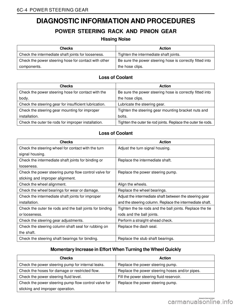
DIAGNOSTIC INFORMATION AND PROCEDURES
POWER STEERING RACK AND PINION GEAR
Hissing Noise
Check the intermediate shaft joints for looseness.
Check the power steering hose for contact with other
components.ChecksActionTighten the intermediate shaft joints.
Be sure the power steering hose is correctly fitted into
the hose clips.
Loss of Coolant
Check the power steering hose for contact with the
body.
Check the steering gear for insufficient lubrication.
Check the steering gear mounting for improper
installation.
Check the outer tie rods for improper installation.ChecksActionBe sure the power steering hose is correctly fitted into
the hose clips.
Lubricate the steering gear.
Tighten the steering gear mounting bracket nuts and
bolts.
Tighten the outer tie rod joints. Replace the outer tie rods.
Loss of Coolant
Check the steering wheel for contact with the turn
signal housing.
Check the intermediate shaft joints for binding or
looseness.
Check the power steering pump flow control valve for
sticking and improper alignment.
Check the wheel alignment.
Check the wheel bearings for wear or damage.
Check the intermediate shaft joints for improper
installation.
Check the outer tie rods and the ball joints for binding
or looseness.
Check the steering gear adjustments.
Check the steering column shaft seal for rubbing on
the shaft.
Check the steering shaft bearings for binding.ChecksActionAdjust the turn signal housing.
Replace the intermediate shaft.
Replace the power steering pump.
Align the wheels.
Replace the wheel bearings.
Adjust the intermediate shaft between the steering gear
and the steering column. Replace the intermediate shaft.
Tighten the tie rods and the ball joints. Replace the tie
rods and the ball joints.
Perform a straight-ahead check.
Replace the dash seal.
Replace the stub shaft bearings.
Check the power steering pump for internal leaks.
Check the hoses for damage or restricted flow.
Check the power steering fluid level.
Check the power steering pump flow control valve for
sticking and improper operation.ChecksActionReplace the power steering pump.
Replace the power steering hoses and/or pipes.
Fill the power steering fluid reservoir.
Replace the power steering pump.
Momentary Increase in Effort When Turning the Wheel Quickly
Page 1474 of 2053

SSANGYONG MY2002
6C-6 POWER STEERING GEAR
POWER STEERING RACK AND
PINION GEAR BENCH TESTING
Removal and Installation Procedure
Notice: Pressure checks or pressure and flow checks
may also be conducted using this setup.
1. Disconnect and remove the power steering gear.
Refer to “Rack and Pinion Assembly” in this
section.
2. Place the power steering gear on a bench next to
the vehicle.
3. Disconnect the pressure line at the point where the
hose connects to the pipe. Extend this line to reach
the power steering gear on the bench.
4. Disconnect the return line from the power steering
fluid reservoir. Extend this line to reach the power
steering gear on the bench.
5. Connect the power steering pipes to the power
steering gear.
6. Start the engine and allow it to idle for 10 seconds.
7. Check the power steering fluid level. Refer to
Section 6A, Power Steering System.
8. Start the engine and turn the rack and pinion stub
shaft a full turn in each direction. Hold the shaft
against each stop for 5 seconds.
9. Inspect for possible leak points. Refer to Section
6A, Power Steering System.
Installation Procedure
1. Stop the engine.
2. Disconnect the power steering pipes from the power
steering gear.
KAA6C020
3. Remove the extensions and reconnect the pressure
and return lines.
4. Install and connect the power steering gear. Refer
to “Rack and Pinion Assembly” in this section.
5. Start the engine and allow it to idle for 10 seconds.
6. Check the power steering fluid level. Refer to
Section 6A, Power Steering System.
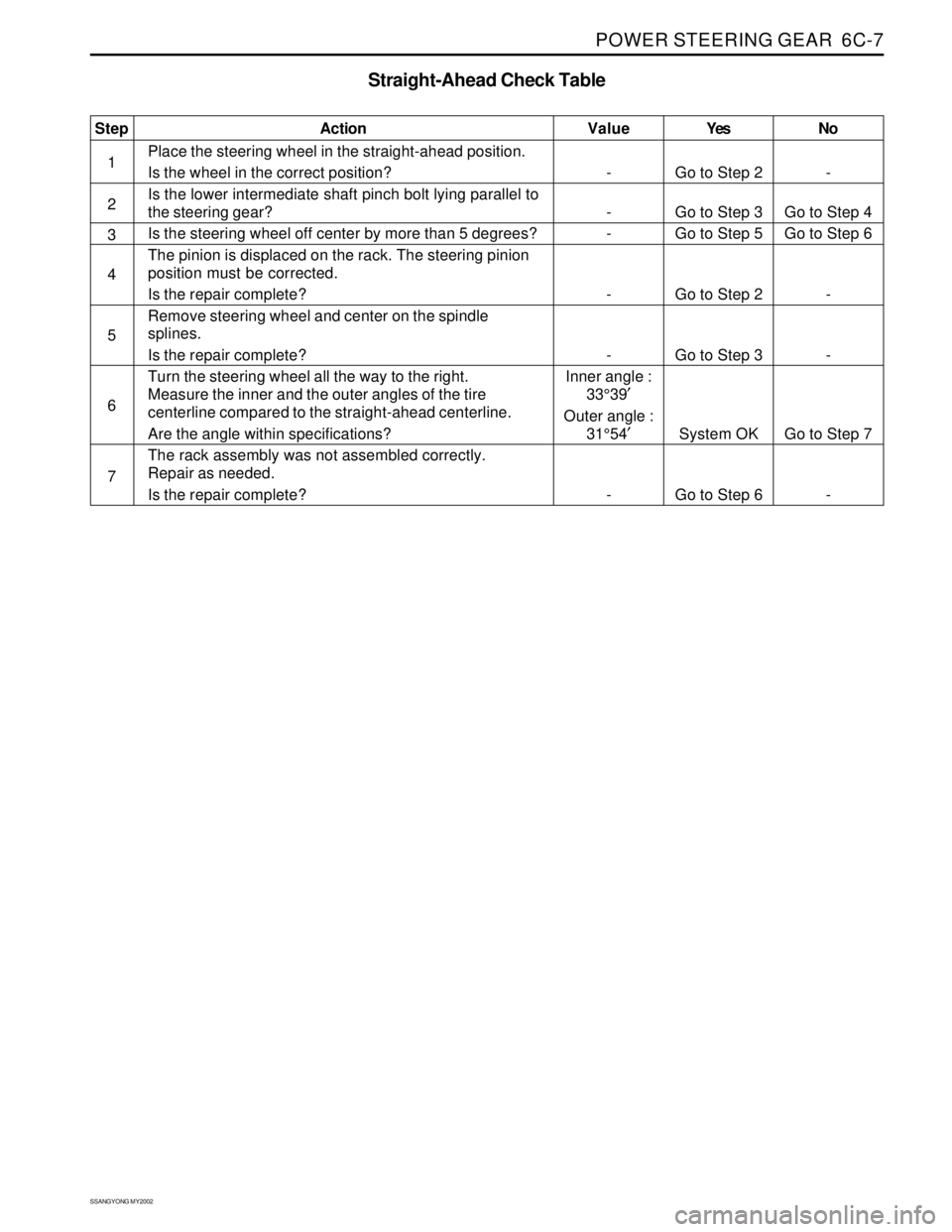
STRAIGHT-AHEAD CHECK
After all the necessary operations on the steering gear
are completed (removing and installing, disassembling
and assembling), check the exact straight-ahead posi-
tion of the steering in each case.
With the vehicle on the floor, place the steering wheel
in the straight-ahead position. Mark the centerline of
both tires on the floor. Turn the steering wheel all the
way to the right and mark the new centerline of both
tires on the floor.
Page 1475 of 2053

POWER STEERING GEAR 6C-7
SSANGYONG MY2002
Yes
Go to Step 2
Go to Step 3
Go to Step 5
Go to Step 2
Go to Step 3
System OK
Go to Step 6No
-
Go to Step 4
Go to Step 6
-
-
Go to Step 7
- Value
-
-
-
-
-
Inner angle :
33°39′
Outer angle :
31°54′
-Step
1
2
3
4
5
6
7Action
Place the steering wheel in the straight-ahead position.
Is the wheel in the correct position?
Is the lower intermediate shaft pinch bolt lying parallel to
the steering gear?
Is the steering wheel off center by more than 5 degrees?
The pinion is displaced on the rack. The steering pinion
position must be corrected.
Is the repair complete?
Remove steering wheel and center on the spindle
splines.
Is the repair complete?
Turn the steering wheel all the way to the right.
Measure the inner and the outer angles of the tire
centerline compared to the straight-ahead centerline.
Are the angle within specifications?
The rack assembly was not assembled correctly.
Repair as needed.
Is the repair complete?
Straight-Ahead Check Table
Page 1478 of 2053

SSANGYONG MY2002
6C-10 POWER STEERING GEAR
KAA6C090
KAA6C100
KAA6C110
KAA6C080
4. Loosen the outer tie rod adjusting nut and remove
the outer tie rod by twisting it off the inner tie rod.
Installation Notice:
After Installation, perform a front toe adjustment.
Refer to Section 2B, Wheel Alignment.
DUST BOOT
Removal and Installation Procedure
1. Raise and suitably support the vehicle.
2. Remove the wheel. Refer to Section 2E, Tires and
wheels.
3. Remove the outer tie rod. Refer to “Outer Tie Rod”
in this section.
4. Remove the dust boot retaining clamps.
5. Remove the dust boot.
Installation Notice:
After Installation, perform a front toe adjustment.
Refer to Section 2B, Wheel Alignment.
INTERMEDIATE SHAFT
Removal and Installation Procedure
1. Turn the steering wheel until it is horizontal. This
is the straight-ahead position. Make a mark on
the stub shaft housing that lines up with a mark
on the intermediate shaft lower universal joint.
Installation Notice:
When attaching the lower universal joint, the
marks on the intermediate shaft and on the stub
shaft should line up