head SSANGYONG KORANDO 1997 Service Repair Manual
[x] Cancel search | Manufacturer: SSANGYONG, Model Year: 1997, Model line: KORANDO, Model: SSANGYONG KORANDO 1997Pages: 2053, PDF Size: 88.33 MB
Page 1482 of 2053

SSANGYONG MY2002
6C-14 POWER STEERING GEAR
8. Counterhold the pinion-side inner tie rod and re-
move the cylinder-side inner tie rod.
Installation Notice:
To prevent the inner tie rods from loosening,
use Loctite 242 (or equivalent) on both inner
tie rod connections to secure them to the rack
shaft.
KAA6C180
KAA6C190
KAA6C210
KAA6C200
Important: The retaining ring can be released by
inserting a small screwdriver through the hole in
the side of the housing.
9. Remove the bulkhead inner cylinder retaining ring.
Installation Notice:
Coat all the seals with power steering fluid to
ensure proper sealing.
10. Place a rag over the rack, counterhold the rack
assembly on the teeth with a wrench, and remove
the pinion-side inner tie rod.
Installation Notice:
The right and left inner tie rods are unequal in
length. Be sure to install the correct inner tie
rod on the proper side of the power steering
gear.
VALVE AND PINION ASSEMBLY
Disassembly and Assembly Procedure
1. Remove the rack and pinion steering assembly
from the vehicle. Refer to “Rack and Pinion
Assembly” in this section.
2. Remove the dust cover from the lower end of the
housing.
Notice: If the stub shaft is not held, damage to
the pinion teeth will occur.
3. While holding the stub shaft with a wrench, remove
the locknut from the pinion.
Page 1487 of 2053

SECTION 6E
POWER STEERING AND COLUMN
TABLE OF CONTENTS
Description and Operation...................................6E-2
General Description.............................................6E-2
Ignition Switch Keyhole Lamp..............................6E-2
Ignition Key Reminder .........................................6E-2
Component Locator.............................................6E-3
Diagnostic Information and Procedures..............6E-4
Steering Wheel Freeplay Inspection.....................6E-4
Steering Effort Inspection.....................................6E-4
Steering Column Diagnosis..................................6E-5
Repair Instructions................................................6E-9On-Vehicle Service.................................................6E-9
Headlamp/Turn Signal Switch and Lever...............6E-9
Wiper Switch and Lever.....................................6E-10
Steering Wheel With Sir.....................................6E-10
Ignition Lock Cylinder and Switch......................6E-11
Steering Column................................................6E-12
Specifications.....................................................6E-14
Fastener Tightening Specifications.....................6E-14
Special Tools and Equipment............................6E-15
Special Tools Table............................................6E-15
Page 1488 of 2053

SSANGYONG MY2002
6E-2 POWER STEERING AND COLUMN
GENERAL DESCRIPTION
Caution: To ensure the energy-absorbing action of
the steering column, it is important to use only the
specified screws, bolts, and nuts, tightened to the
specified torque.
In addition to the steering function, the steering column
provides safety and security.
The energy-absorbing column is designed to compress
in a front-end collision to lessen the chance of driver
injury.
The ignition switch and the lock are mounted on the
column, allowing the ignition and steering operations
to be locked to inhibit theft of the car.
The column levers trigger the turn signals, the headlight
beams, and the windshield washer and wipers.
A tilt steering column uses a spherical joint to allow
the steering wheel to tilt up and down. This enables
the driver to adjust the steering wheel to a comfortable
position.
Notice: Apply a thin coat of lithium grease to all friction
points when reassembling.
The column may be disassembled and reassembled
easily.
DESCRIPTION AND OPERATION
IGNITION SWITCH KEYHOLE LAMP
For description and lamp replacement information, Re-
fer to Section 9B, Lighting Systems.
IGNITION KEY REMINDER
The ignition key reminder alerts the driver that the key
is still in the ignition when the driver attempts to exit
the vehicle.
An internal switch in the ignition lock cylinder supplies
battery voltage to the reminder chime module when all
of the following conditions are true:
•The key is in the ignition switch.
The ignition is OFF.
The driver’s door is open.
For information on removal and installation of the re-
minder chime module, Refer to Section 9E, Instrumen-
tation/Driver Information.
Page 1489 of 2053

POWER STEERING AND COLUMN 6E-3
SSANGYONG MY2002
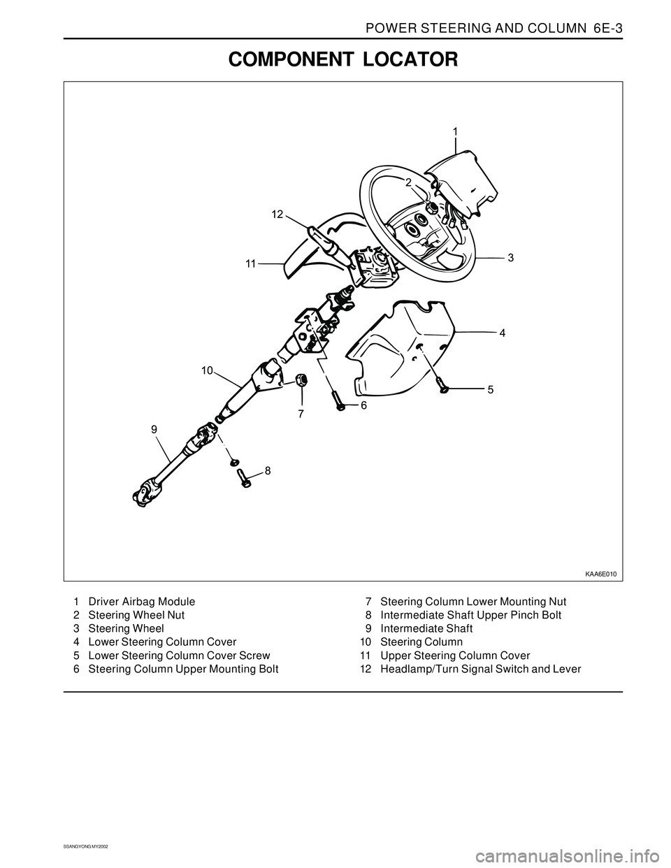
COMPONENT LOCATOR
KAA6E010
1 Driver Airbag Module
2 Steering Wheel Nut
3 Steering Wheel
4 Lower Steering Column Cover
5 Lower Steering Column Cover Screw
6 Steering Column Upper Mounting Bolt7 Steering Column Lower Mounting Nut
8 Intermediate Shaft Upper Pinch Bolt
9 Intermediate Shaft
10 Steering Column
11 Upper Steering Column Cover
12 Headlamp/Turn Signal Switch and Lever
Page 1490 of 2053

SSANGYONG MY2002
6E-4 POWER STEERING AND COLUMN
DIAGNOSTIC INFORMATION AND PROCEDURES
STEERING WHEEL FREEPLAY
INSPECTION
KAA6E020
Inspection Procedure
1. Start the engine and set the wheels in straight
ahead position.
2. Slightly move the steering wheel to the left and
right and measure steering wheel free play when
the front wheel is start to move.
Notice: If exceeds specification, the steering
column shaft connections and steering linkage
clearance. Replace or repair if necessary.
StandardMax. 30 mm
STEERING EFFORT INSPECTION
KAA6E030
Inspection Procedure
1. Place a vehicle on the paved flat ground with front
wheels in a straight ahead position.
2. Start the engine and run it at 1,000 rpm.
3. Using a scale, measure the steering effort in both
directions.
Notice : The difference in steering effort of left
and right should be within 0.6 kg.
StandardMax. 3.0 kg
Page 1495 of 2053

POWER STEERING AND COLUMN 6E-9
SSANGYONG MY2002
KAA6E060
KAA6E040
ON-VEHICLE SERVICE
HEADLAMP/TURN SIGNAL
SWITCH AND LEVER
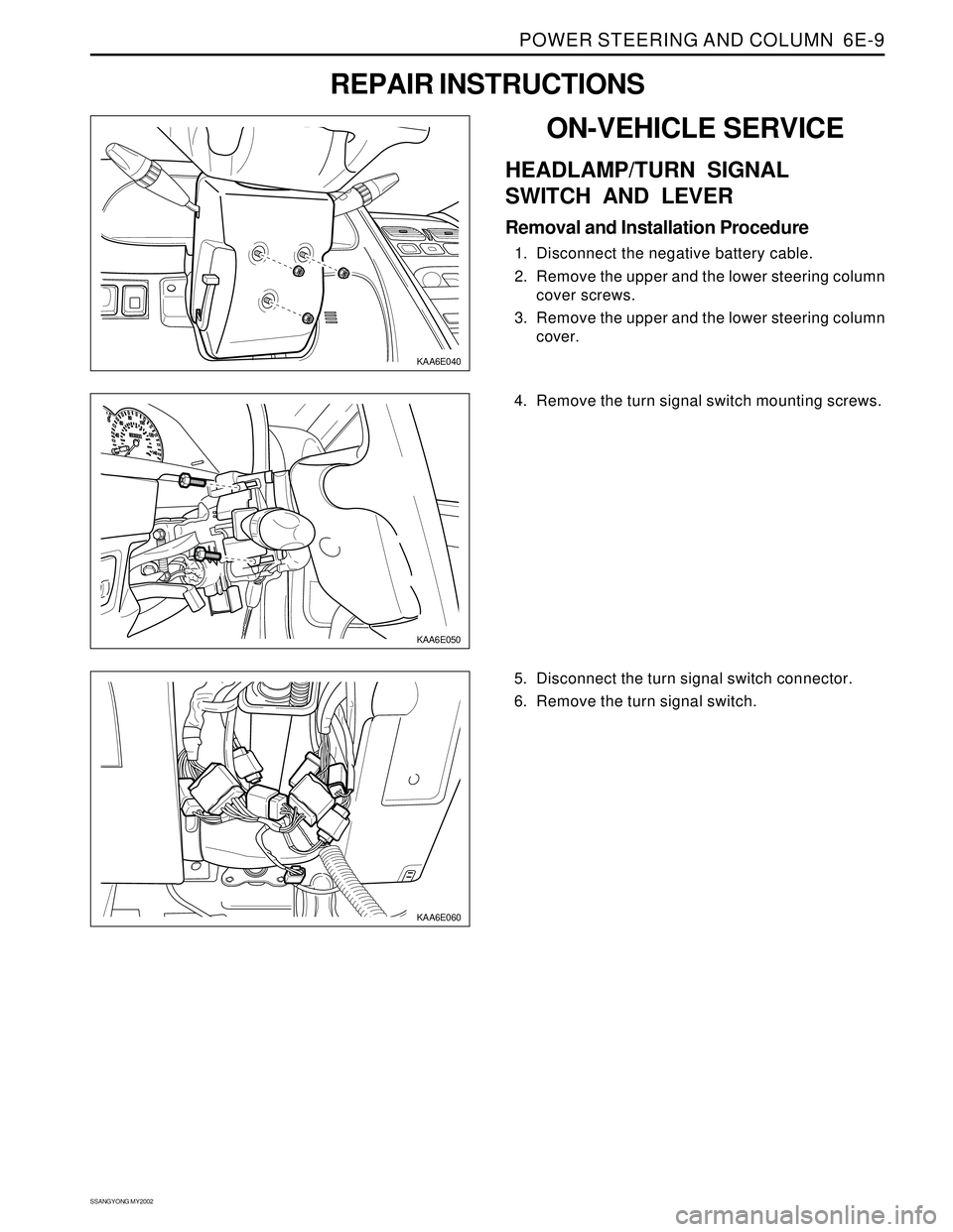
Removal and Installation Procedure
1. Disconnect the negative battery cable.
2. Remove the upper and the lower steering column
cover screws.
3. Remove the upper and the lower steering column
cover.
REPAIR INSTRUCTIONS
KAA6E050
4. Remove the turn signal switch mounting screws.
5. Disconnect the turn signal switch connector.
6. Remove the turn signal switch.
Page 1498 of 2053

SSANGYONG MY2002
6E-12 POWER STEERING AND COLUMN
KAA6E040
KAA6E120
STEERING COLUMN
Important: Remove the steering column only if the
following conditions exist:
The steering column requires replacement.
The steering and the ignition lock housing require
replacement.
Another operation requires the removal of the
steering column
Notice: The steering column is extremely
susceptible to damage after it has been removed
from the vehicle. Dropping the column assembly
on its end or hammering the end of the steering
shaft can collapse the steering shaft or loosen the
plastic injections which maintain column rigidity.
Leaning on the column can cause it to bend or
deform. Any of the above damage can impair the
column’s collapsible design. If it is necessary to
remove the steering wheel, use only the specified
steering wheel puller.
Removal and Installation Procedure
1. Disconnect the negative battery cable.
2. Remove the upper and the lower steering column
cover screws.
3. Remove the upper and the lower steering column
cover.
KAA6E060
4. Remove the lower instrument trim panel. Refer to
Section 9E, Instrumentation/Driver Information.
5. Remove the immoblilzer module. Refer to Section
9T, Immobilizer Anti-Theft system.
6. Disconnect the airbag electrical connections.
7. Disconnect electrical switch connections.
8. Adjust the steering to the straight-ahead position.
9. Make a mark on the steering column shaft that
lines up with a mark on the intermediate shaft
upper universal joint.
10. Remove the intermediate shaft upper pinch bolt.
Installation Notice
Tightening Torque 27 Nm (20 lb-ft)
Page 1578 of 2053

SSANGYONG MY2002
8A-2 SEAT BELTS
DESCRIPTION AND OPERATION
DRIVER SEAT BELT WARNING
The driver’s seat belt incorporates a seat belt warning
lamp in the instrument cluster to remind the driver if
the seat belt is not fastened when the ignition is turned
ON. The warning lamp blinks for eight seconds with
chime and goes out.
THREE-POINT FRONT SEAT BELT
WITH PRETENSIONER
The front seat belt contains an electronically controlled
pyrotechnic retractor, pretensioner, which reduces seat
belt slack when it activated in a head-on or angled
front collision. The front seat belt must be replaced
after an accident that causes its activation. At normal
condition the driver’s seat belt operates as emergency
locking retractor (ELR).
Emergency Locking Retractor (ELR)
The ELR seat belt is always unlocked, allowing the
passenger freedom of movement, except in
emergencies such as rapid deceleration, rapid
acceleration, or hard cornering maneuvers.
THREE-POINT REAR OUTBOARD
SEAT BELT
The rear outboard seating position uses the emergency
locking retractor (ELR). Refer to Three-point front seat
belt with pretensioner in this section for details.
TWO-POINT LAP REAR CENTER
SEAT BELT
The two-point lap rear center seat belt is a single contin-
uous length of webbing. The webbing is routed from
the anchor through plate and into a single retractor.
OPERATIONAL AND FUNCTIONAL
CHECKS
Caution:
Keep sharp objects and potentially damaged ob
jects away from seat belts.
Avoid bending or damaging any portion of
buckle or the latch plate
Do not breach or dye the belt webbing. Use only
mild soap and water in order to clean the belts.
When installing the seat belt anchor bolts and
screws, start the bolts and screws by hand in or-
der to prevent cross-threading.
Do not attempt any repairs on the retractor mech-
anisms or covers. Replace any defective assem-
blies with new assemblies.
Replace any belts that are cut or damaged in any
way.
1. Inspect all seat anchor bolts and screws in order to
verify that they are secure.
2. Inspect the seat belt buckle. The buckle must lock
and unlock easily.
3. After inserting the latch into the buckle, tug sharply
on the belt. The buckle must remain locked.
4. Fully extend the shoulder belt portion to make sure
that there is no twisting or tears in the belt.
5. Let the shoulder belt retract fully. The belt should
retract easily.
CHILD SEAT TETHER ANCHOR
There are three child seat tether anchors to hold the
child seat firmly. One is located rear center of ceiling
and two are located on the rear corner of floor.
Page 1640 of 2053

SSANGYONG MY2002
8B-58 SUPPLEMENTAL RESTRAINTS SYSTEM
REPAIR INSTRUCTION
ON-VEHICLE SERVICE
SERVICE PRECAUTION
Caution: The sensing and diagnosis module (SDM)
can maintain sufficient voltage to deploy the airbags
and pretensioner for 0.15 seconds after the ignition
is OFF and the airbag fuse has been removed. If the
airbags or pretensioners are not disconnected, do
not begin service until one minute has passed after
disconnecting power to the SDM. If the airbag are
disconnected, service can begin immediately without
waiting for one-minute time period to expire. Failure
to temporarily disable the SRS during service can
result in unexpected deployment, personal injury,
and otherwise unneeded SRS repairs.
DISABLING THE SUPPLEMENTAL
RESTRAINT SYSTEM (SRS)
1. Turn the steering wheel to the straight-ahead
position.
2. Turn the ignition switch to LOCK and remove the key.
3. Remove the airbag fuse F31 in the I/P fuse block
and wait more than one minute for SRS capacitor to
discharge.
ENABLING THE SUPPLEMENTAL
RESTRAINT SYSTEM (SRS)
Enabling the supplemental restraint system (SRS) is
reverse order of “Disabling the Supplemental Restraint
System (SRS)”.
Caution: Staying well away from the inflator
modules, turn the ignition key switch to ON, and
verify that the airbag indicator illuminates for 4.5
seconds and turns OFF. If it does not operate as
described, perform the “SRS Diagnostic System
Check” referring in this section.
HANDLING, INSTALLATION AND
DIAGNOSIS
Airbag modules should not be subjected to
temperature above 65°C (149°F)
An airbag module or sensing and diagnostic module
(SDM) should not be used if it has been dropped
from height of 0.9 meters (3 feet) or greater.
It is very important for the SDM to be installed flat
on the mounting surface, parallel to the vehicle’s
longitudinal axis.
To avoid setting diagnostic trouble codes (DTCs),
do not apply power to the SRS unless all components
are connected or a diagnostic chart request it.
The SRS Diagnostic System Check must be the
starting point of any SRS diagnostics. The SRS
Diagnostic System Check will verify proper airbag
indicator operation and will lead you to correct chart
to diagnose any SRS malfunctions. Bypassing
these procedures may result in extended diagnostic
time and incorrect parts replacements.
REPAIRS AND INSPECTIONS
REQUIRED AFTER AN ACCIDENT
Caution: any repairs to the vehicle’s structure must
return it to the original production configuration.
Deployment requires replacement of SDM, the
inflator modules, and a dimensional inspection of
the steering column.
If any SRS components are damaged, they must
be replaced. If SRS components mounting points
are damaged, they must be repaired or replaced.
Never use SRS parts from another vehicle. This does
not include remanufactured parts purchased from
an authorized source.
Do not attempt to service the SDM, the clock spring,
or other airbag modules, these items must be
replaced if they are defective.
Verify the part number of replacement airbag
modules. Some inflator modules look identical but
contain different internal components.
ACCIDENT WITH DEPLOYMENT -
COMPONENTS REPLACEMENT
All SRS components must be replaced after frontal crash
involving airbag deployment. After deployment, a
powdery residue may be on the surface of the airbag.
The powder consists primarily of cornstarch (used to
lubricate the bag as it inflates) and by-products of the
chemical reaction. Sodium hydroxide dust (similar to
lye soap) is produced as a by-product of the deployment
reaction. The sodium hydroxide then quickly reacts with
atmospheric moisture and is converted to sodium
carbonate and sodium bicarbonate (also known as
baking soda). Therefore, it is unlikely that sodium
hydroxide will be present after deployment. Replace
the following SRS components.
Caution: Wear gloves and safety glasses during the
disposal procedure. Refer to “Deployed Airbag
Module Disposal Procedure” in this section.
The SDM.
Airbag modules and pretensioners
SRS wiring
Clock spring
Page 1642 of 2053

SSANGYONG MY2002
8B-60 SUPPLEMENTAL RESTRAINTS SYSTEM
KAA8B140
DRIVER AIRBAG MODULE
Removal and installation Procedure
1. Disconnect the negative battery cable.
Caution: The SDM can maintain sufficient
voltage to deploy the airbags for 0.15 seconds
after the Ignition is OFF and the airbag fuse has
been removed. If the airbags are not
disconnected, service cannot begin until one
minute has passed after disconnecting power
to the SDM. If the airbags are disconnected,
service can begin immediately without waiting
for one-minute time period to expire. Failure to
temporarily disable the SRS during service
result in unexpected deployment, personal
injury, and otherwise unneeded SRS repair.
2. Disable the supplemental restraint system (SRS).
Refer to “Disabling the SRS” in this section.
3. Position the steering wheel straight ahead.
4. Remove the driver airbag module mounting bolts.
Installation Notice
Caution: When handling an airbag module,
always keeps the top of the unit facing upward.
This leaves room for the airbag to expand if the
module unexpectedly deploys. Without room
for expansion, a module suddenly propelled
toward a person or object can cause injury or
vehicle damage.
5. Remove the connector from the horn terminal and
the driver airbag module.
6. Remove the driver airbag module.
7. Installation should follow the removal procedure
in the reverse order.
Tightening Torque 8 Nm (71 lb-in)