ESP SSANGYONG KORANDO 1997 Service User Guide
[x] Cancel search | Manufacturer: SSANGYONG, Model Year: 1997, Model line: KORANDO, Model: SSANGYONG KORANDO 1997Pages: 2053, PDF Size: 88.33 MB
Page 437 of 2053
M161 ENGINE CONTROLS 1F2 -- 15
D AEW OO M Y_2000
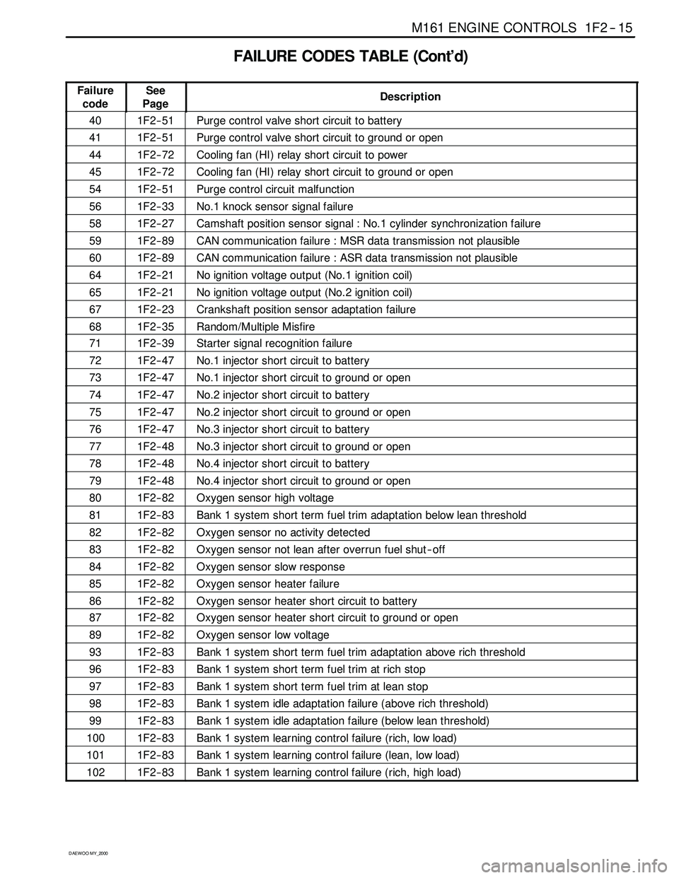
FAILURE CODES TABLE (Cont’d)
Failure
codeSee
PageDescription
401F2 -- 51Purge control valve short circuit to battery
411F2 -- 51Purge control valve short circuit to ground or open
441F2 -- 72Cooling fan (HI) relay short circuit to power
451F2 -- 72Cooling fan (HI) relay short circuit to ground or open
541F2 -- 51Purge control circuit malfunction
561F2 -- 33No.1 knock sensor signal failure
581F2 -- 27Camshaft position sensor signal : No.1 cylinder synchronization failure
591F2 -- 89CAN communication failure : MSR data transmission not plausible
601F2 -- 89CAN communication failure : ASR data transmission not plausible
641F2 -- 21No ignition voltage output (No.1 ignition coil)
651F2 -- 21No ignition voltage output (No.2 ignition coil)
671F2 -- 23Crankshaft position sensor adaptation failure
681F2 -- 35Random/Multiple Misfire
711F2 -- 39Starter signal recognition failure
721F2 -- 47No.1 injector short circuit to battery
731F2 -- 47No.1 injector short circuit to ground or open
741F2 -- 47No.2 injector short circuit to battery
751F2 -- 47No.2 injector short circuit to ground or open
761F2 -- 47No.3 injector short circuit to battery
771F2 -- 48No.3 injector short circuit to ground or open
781F2 -- 48No.4 injector short circuit to battery
791F2 -- 48No.4 injector short circuit to ground or open
801F2 -- 82Oxygen sensor high voltage
811F2 -- 83Bank 1 system short term fuel trim adaptation below lean threshold
821F2 -- 82Oxygen sensor no activity detected
831F2 -- 82Oxygen sensor not lean after overrun fuel shut -- off
841F2 -- 82Oxygen sensor slow response
851F2 -- 82Oxygen sensor heater failure
861F2 -- 82Oxygen sensor heater short circuit to battery
871F2 -- 82Oxygen sensor heater short circuit to ground or open
891F2 -- 82Oxygen sensor low voltage
931F2 -- 83Bank 1 system short term fuel trim adaptation above rich threshold
961F2 -- 83Bank 1 system short term fuel trim at rich stop
971F2 -- 83Bank 1 system short term fuel trim at lean stop
981F2 -- 83Bank 1 system idle adaptation failure (above rich threshold)
991F2 -- 83Bank 1 system idle adaptation failure (below lean threshold)
1001F2 -- 83Bank 1 system learning control failure (rich, low load)
1011F2 -- 83Bank 1 system learning control failure (lean, low load)
1021F2 -- 83Bank 1 system learning control failure (rich, high load)
Page 458 of 2053
1F2 -- 40 M161 ENGINE CONTROLS
D AEW OO M Y_2000
FUEL SYSTEM
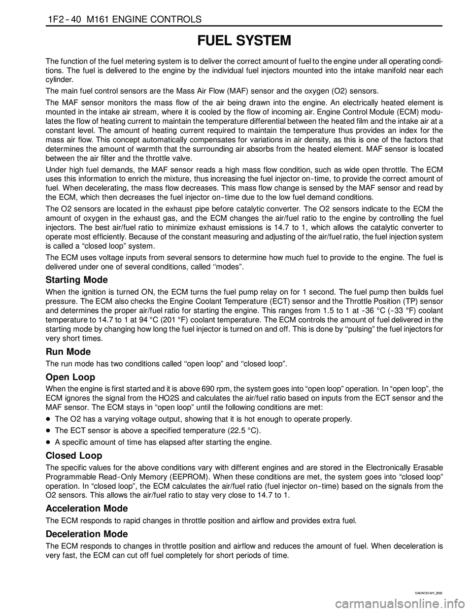
The function of the fuel metering system is to deliver the correct amount of fuel to the engine under all operating condi-
tions. The fuel is delivered to the engine by the individual fuel injectors mounted into the intake manifold near each
cylinder.
The main fuel control sensors are the Mass Air Flow (MAF) sensor and the oxygen (O2) sensors.
The MAF sensor monitors the mass flow of the air being drawn into the engine. An electrically heated element is
mounted in the intake air stream, where it is cooled by the flow of incoming air. Engine Control Module (ECM) modu-
lates the flow of heating current to maintain the temperature differential between the heated film and the intake air at a
constant level. The amount of heating current required to maintain the temperature thus provides an index for the
mass air flow. This concept automatically compensates for variations in air density, as this is one of the factors that
determines the amount of warmth that the surrounding air absorbs from the heated element. MAF sensor is located
between the air filter and the throttle valve.
Under high fuel demands, the MAF sensor reads a high mass flow condition, such as wide open throttle. The ECM
uses this information to enrich the mixture, thus increasing the fuel injector on-- time, to provide the correct amount of
fuel. When decelerating, the mass flow decreases. This mass flow change is sensed by the MAF sensor and read by
the ECM, which then decreases the fuel injector on-- time due to the low fuel demand conditions.
The O2 sensors are located in the exhaust pipe before catalytic converter. The O2 sensors indicate to the ECM the
amount of oxygen in the exhaust gas, and the ECM changes the air/fuel ratio to the engine by controlling the fuel
injectors. The best air/fuel ratio to minimize exhaust emissions is 14.7 to 1, which allows the catalytic converter to
operate most efficiently. Because of the constant measuring and adjusting of the air/fuel ratio, the fuel injection system
is called a “closed loop” system.
The ECM uses voltage inputs from several sensors to determine how much fuel to provide to the engine. The fuel is
delivered under one of several conditions, called ‘‘modes”.
Starting Mode
When the ignition is turned ON, the ECM turns the fuel pump relay on for 1 second. The fuel pump then builds fuel
pressure. The ECM also checks the Engine Coolant Temperature (ECT) sensor and the Throttle Position (TP) sensor
and determines the proper air/fuel ratio for starting the engine. This ranges from 1.5 to 1 at -- 36°C(--33°F) coolant
temperature to 14.7 to 1 at 94°C (201°F) coolant temperature. The ECM controls the amount of fuel delivered in the
starting mode by changing how long the fuel injector is turned on and off. This is done by ‘‘pulsing” the fuel injectors for
very short times.
Run Mode
The run mode has two conditions called ‘‘open loop” and ‘‘closed loop”.
Open Loop
When the engine is first started and it is above 690 rpm, thesystem goes into “open loop” operation. In “open loop”, the
ECM ignores the signal from the HO2S and calculates the air/fuel ratio based on inputs from the ECT sensor and the
MAF sensor. The ECM stays in “open loop” until the following conditions are met:
DThe O2 has a varying voltage output, showing that it is hot enough to operate properly.
DThe ECT sensor is above a specified temperature (22.5°C).
DA specific amount of time has elapsed after starting the engine.
Closed Loop
The specific values for the above conditions vary with different engines and are stored in the Electronically Erasable
Programmable Read -- Only Memory (EEPROM). When these conditions are met, thesystem goes into “closed loop”
operation. In “closed loop”, the ECM calculates the air/fuel ratio (fuel injector on-- time) based on the signals from the
O2 sensors. This allows the air/fuel ratio to stay very close to 14.7 to 1.
Acceleration Mode
The ECM responds to rapid changes in throttle position and airflow and provides extra fuel.
Deceleration Mode
The ECM responds to changes in throttle position and airflow and reduces the amount of fuel. When deceleration is
very fast, the ECM can cut off fuel completely for short periods of time.
Page 486 of 2053
1F2 -- 68 M161 ENGINE CONTROLS
D AEW OO M Y_2000
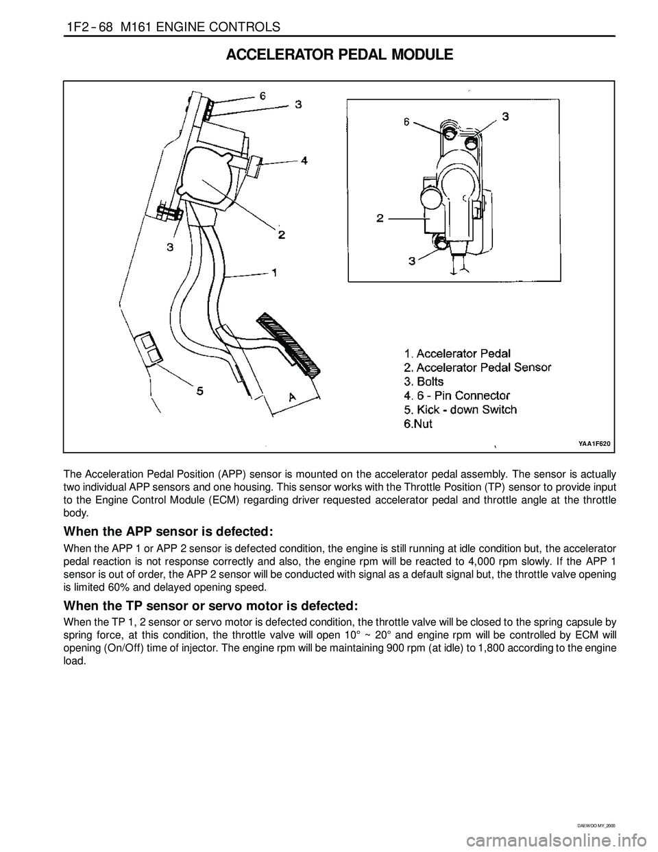
ACCELERATOR PEDAL MODULE
YAA1F620
The Acceleration Pedal Position (APP) sensor is mounted on the accelerator pedal assembly. The sensor is actually
two individual APP sensors and one housing. This sensor works with the Throttle Position (TP) sensor to provide input
to the Engine Control Module (ECM) regarding driver requested accelerator pedal and throttle angle at the throttle
body.
When the APP sensor is defected:
When the APP 1 or APP 2 sensor is defected condition, the engine is still running at idle condition but, the accelerator
pedal reaction is not response correctly and also, the engine rpmwill be reacted to 4,000 rpm slowly. If the APP 1
sensor is out of order, the APP 2 sensor will be conducted with signal as a default signal but, the throttle valve opening
is limited 60% and delayed opening speed.
When the TP sensor or servo motor is defected:
When the TP 1, 2 sensor or servo motor is defected condition, the throttle valvewill be closed to the spring capsule by
spring force, at this condition, the throttle valvewillopen 10°~20°and engine rpmwill be controlled by ECM will
opening (On/Off) time of injector. Theengine rpmwill be maintaining 900 rpm (at idle) to 1,800 according to theengine
load.
Page 487 of 2053
M161 ENGINE CONTROLS 1F2 -- 69
D AEW OO M Y_2000
KAB1F270
Failure
CodeDescriptionTrouble AreaMaintenance Hint
122
Acceleration pedal
position sensor signal
failureWhen malfunction of APP
Sensor
160
Acceleration pedal
position 1 sensor low
voltageAPP 1 sensor short circuit to
ground or open
161
Acceleration pedal
position sensor 1 high
voltageAPP 1 sensor short circuit to
power
DMonitoring the actual values through
162
Acceleration pedal
position sensor 2 low
voltageAPP 2 sensor short circuit to
ground or open
Monitoringtheactualvaluesthrough
scan tool
DInspection the ECM pin 31, 47, 32, 48,
59, 51 about short circuit or open with
badcontact
163
Acceleration pedal
position sensor 2 high
voltageAPP 2 sensor short circuit to
power
badcontact
DInspection the APP sensor
DInspection the ECM
164
Accelerator pedal
position sensor 1 not
plausible with
accelerator pedal
position sensor 2
When difference between
APP 1 sensor and APP 2
sensor
167
Both setpoint
Accelerator pedal
position sensor defectiveWhen defective of both APP
sensor
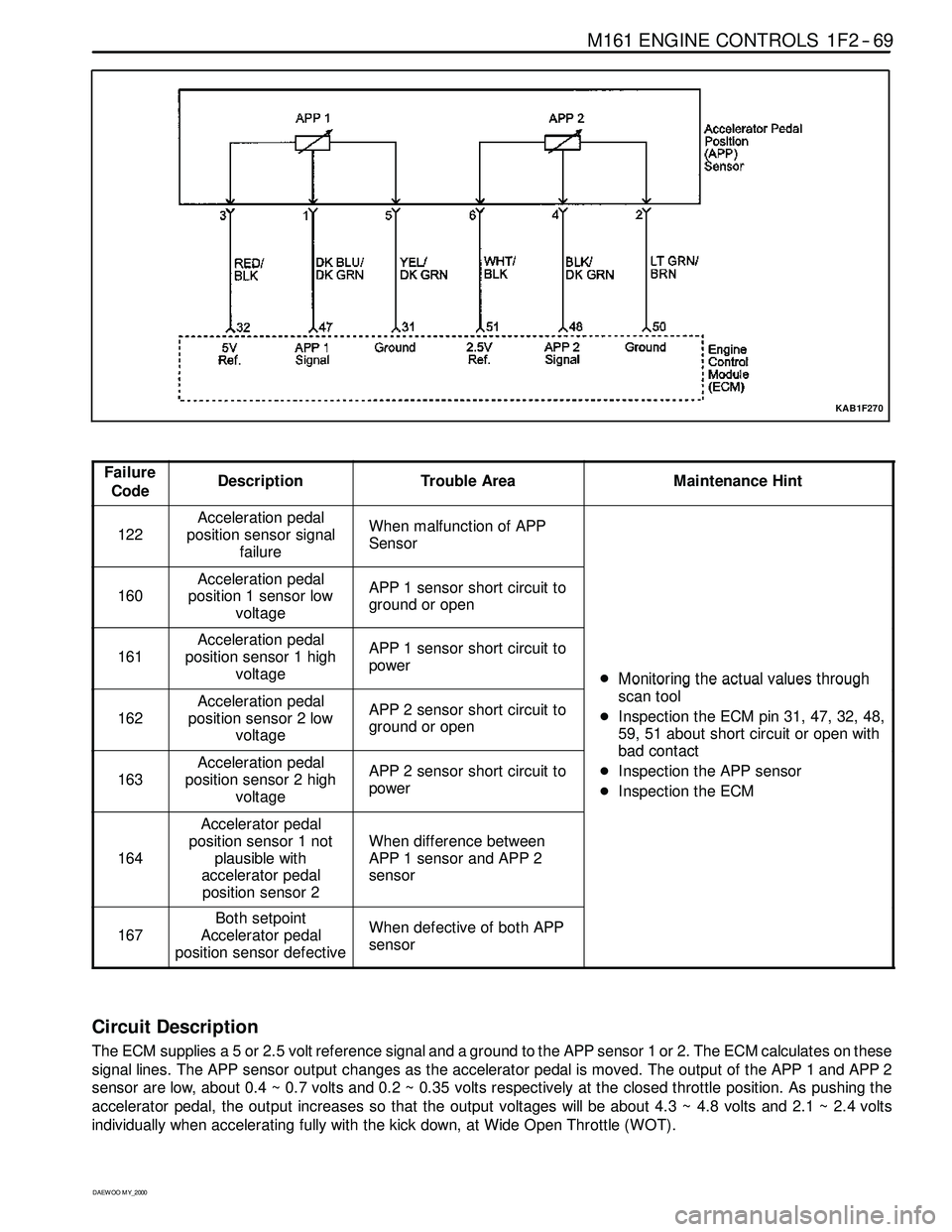
Circuit Description
The ECM supplies a 5 or 2.5 volt reference signal and a ground to the APP sensor 1 or 2. The ECM calculates on these
signal lines. The APP sensor output changes as the accelerator pedal is moved. The output of the APP 1 and APP 2
sensor are low, about 0.4 ~ 0.7 volts and 0.2 ~ 0.35 volts respectively at the closed throttle position. As pushing the
accelerator pedal, the output increases so that the output voltageswill be about 4.3 ~ 4.8 volts and 2.1 ~ 2.4 volts
individually when accelerating fully with the kick down, at Wide Open Throttle (WOT).
Page 500 of 2053
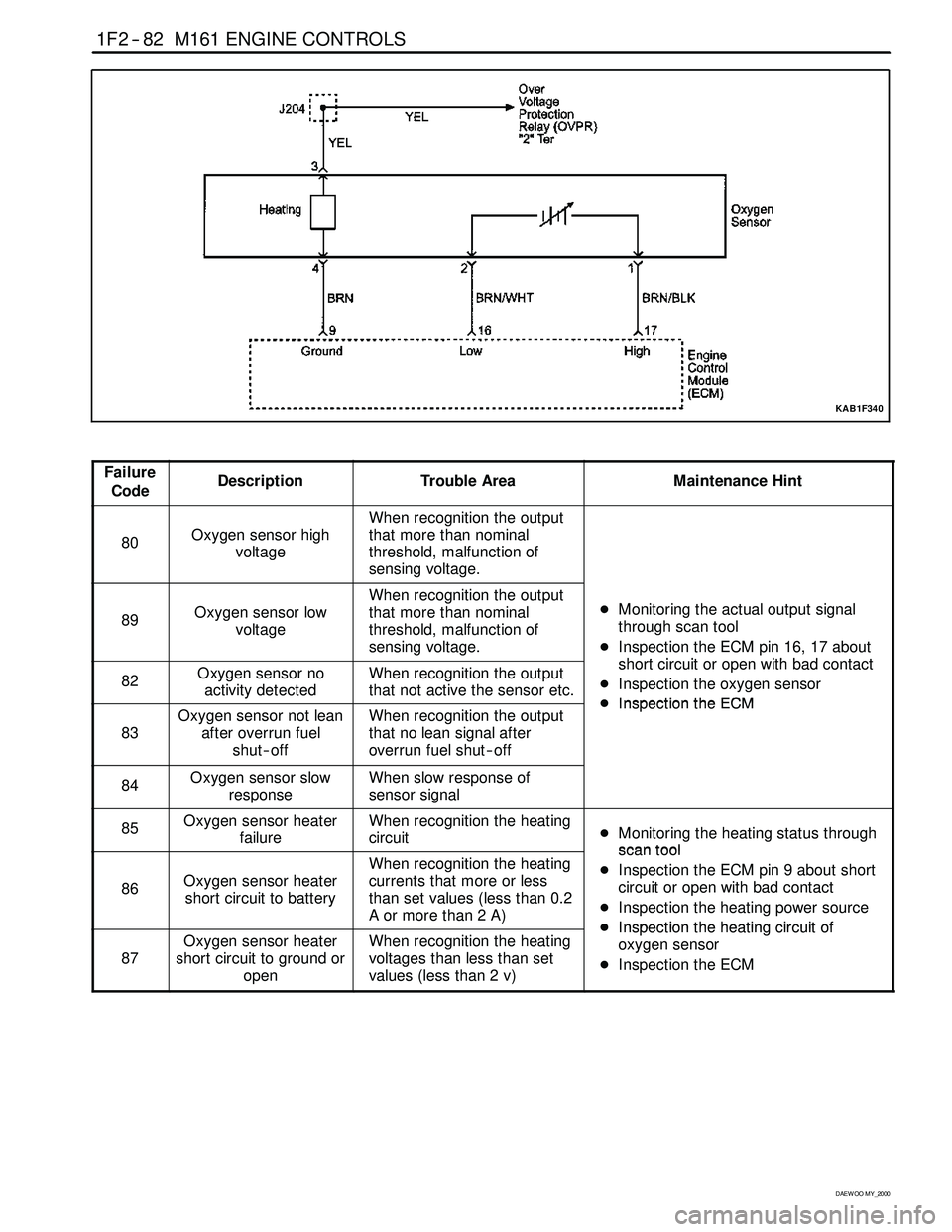
1F2 -- 82 M161 ENGINE CONTROLS
D AEW OO M Y_2000
KAB1F340
Failure
CodeDescriptionTrouble AreaMaintenance Hint
80Oxygen sensor high
voltage
When recognition the output
that more than nominal
threshold, malfunction of
sensing voltage.
89Oxygen sensor low
voltage
When recognition the output
that more than nominal
threshold, malfunction of
sensing voltage.DMonitoring the actual output signal
through scan tool
DInspection the ECM pin 16, 17 about
htiitithbdtt
82Oxygen sensor no
activity detectedWhen recognition the output
that not active the sensor etc.short circuit or open with bad contact
DInspection the oxygen sensor
DInspectiontheECM
83
Oxygen sensor not lean
after overrun fuel
shut -- offWhen recognition the output
that no lean signal after
overrun fuel shut -- offDInspectiontheECM
84Oxygen sensor slow
responseWhen slow response of
sensor signal
85Oxygen sensor heater
failureWhen recognition the heating
circuitDMonitoring the heating status through
scantool
86Oxygen sensor heater
short circuit to battery
When recognition the heating
currents that more or less
than set values (less than 0.2
Aormorethan2A)scantool
DInspection the ECM pin 9 about short
circuit or open with bad contact
DInspection the heating power source
DInspectiontheheatingcircuitof
87
Oxygen sensor heater
short circuit to ground or
openWhen recognition the heating
voltages than less than set
values (less than 2 v)DInspectiontheheating circuitof
oxygen sensor
DInspection the ECM
Page 651 of 2053
1B3 -- 102 OM600 ENGINE MECHANICAL
D AEW OO M Y_2000
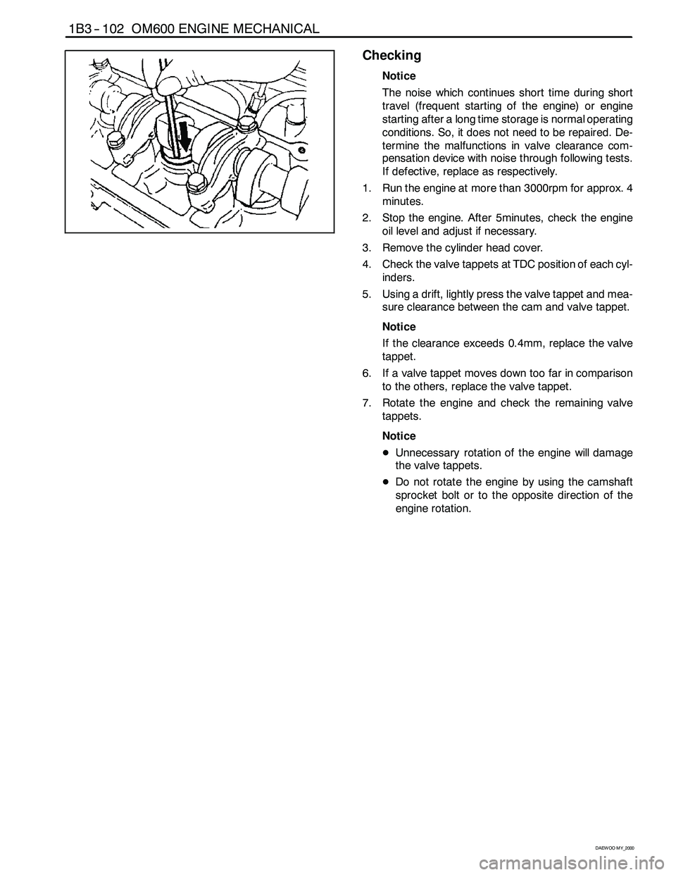
Checking
Notice
The noise which continues short time during short
travel (frequent starting of the engine) or engine
starting after a long time storage is normal operating
conditions. So, it does not need to be repaired. De-
termine the malfunctions in valve clearance com-
pensation device with noise through following tests.
If defective, replace as respectively.
1. Run the engine at more than 3000rpm for approx. 4
minutes.
2. Stop the engine. After 5minutes, check the engine
oil level and adjust if necessary.
3. Remove the cylinder head cover.
4. Check the valve tappets at TDC position of each cyl-
inders.
5. Using a drift, lightly press the valve tappet and mea-
sure clearance between the cam and valve tappet.
Notice
If the clearance exceeds 0.4mm, replace the valve
tappet.
6. If a valve tappet moves down too far in comparison
to the others, replace the valve tappet.
7. Rotate the engine and check the remaining valve
tappets.
Notice
DUnnecessary rotation of the engine will damage
the valve tappets.
DDo not rotate the engine by using the camshaft
sprocket bolt or to the opposite direction of the
engine rotation.
Page 821 of 2053
SSANGYONG MY2002
2B-2 WHEEL ALIGNMENT
FOUR WHEEL ALIGNMENT
The first responsibility of engineering is to design safe
steering and suspension systems. Each component
must be strong enough to withstand and absorb extreme
punishment. Both the steering system and the front
and the rear suspension must function geometrically
with the body mass.
The steering and the suspension systems require that
the front wheels self-return and that the tire rolling effor t
and the road friction be held to a negligible force in
order to allow the customer to direct the vehicle with
the least effort and the most comfort.
A complete wheel alignment check should include mea-
surements of the rear toe and camber.
Four-wheel alignment assures that all four wheels will
be running in precisely the same direction.
When the vehicle is geometrically aligned, fuel economy
and tire life are at their peak, and steering and perfor
mance are maximized.
TOE-IN
Toe-in is the turning in of the tires, while toe-out is the
turning out of the tires from the geometric centerline or
thrust line. The toe ensures parallel rolling of the wheels.
The toe serves to offset the small deflections of the
wheel support system which occur when the vehicle is
rolling forward. The specified toe angle is the setting
which achieves 0 degrees of toe when the vehicle is
moving.
Incorrect toe-in or toe-out will cause tire wear and re
duced fuel economy. As the individual steering and
sus-pension components wear from vehicle mileage,
additional toe will be needed to compensate for the
wear.
Always correct the toe dimension last.
CASTER
Caster is the tilting of the uppermost point of the steering
axis either forward or backward from the vertical when
viewed from the side of the vehicle. A backward tilt is
positive, and a forward tilt is negative. Caster influences
directional control of the steering but does not affect
tire wear. Weak springs or overloading a vehicle will
affect caster. One wheel with more positive caster will
pull toward the center of the car. This condition will
cause the car to move or lean toward the side with the
least amount of positive caster. Caster is measured in
degrees.
CAMBER
Camber is the tilting of the top of the tire from the
vertical when viewed from the front of the vehicle. When
the tires tilt outward, the camber is positive. When the
tires tilt inward, the camber is negative. The camber
angle is measured in degrees from the vertical. Camber
in-fluences both directional control and tire wear.
If the vehicle has too much positive camber, the outside
shoulder of the tire will wear. If the vehicle has too
much negative camber, the inside shoulder of the tire
will wear.
DESCRIPTION AND OPERATION
Page 857 of 2053
TIRE AND WHEELS 2E-3
SSANGYONG MY2002
TIRE CHAIN USAGE
Due to limited tire-to-body clearance on certain
vehicles, recommendations for tire chain use are
published in the Owner’s Manual. When tire chains
need to be used, most current Ssangyong vehicles
require SAE Class “S” tire chains. These may also be
designated as 1100 Series, type PL tire chains. These
chains are specifically designed to limit the “fly off”
effect which occurs when the wheel rotates.
Be sure that only fine-link chains are used which do
not add more than 15 mm (0.590 inch), including the
lock, to the tread surface and the inner sides of the
tires. Manufacturers of tire chains have a specific chain
size for each tire size to ensure a proper fit when the chain
is installed. Be sure to purchase the correct chains for the
tires on which they are to be used. Use rubber adjusters to
take up any slack or clearance in loose chains.
Use of chains may adversely affect vehicle handling.
When tire chains are installed, follow these precautions:
Adjust speed to road conditions.
Avoid sharp turns.
Avoid locked-wheel braking.
To prevent chain damage to the vehicle, install the
chains on the front tires as tightly as possible. Tighten
them again after driving 0.4 to 0.8 kilometer (0.3 to 0.5
mile). The use of chains on the rear tires is not recom-
mended because they may contact the vehicle and pos-
sibly damage it. If chains must be used on the rear
tires, be sure there is sufficient clearance between the
chains and the body. Do not exceed 70 km/h (45 mph)
or the chain manufacturer’s speed limit, if lower. Avoid
large bumps, potholes, severe turns and any other
maneuvers which could cause the tires to bounce.
Follow any other instructions of the chain manufacturer
which do not disagree with the above instructions.
REPLACEMENT TIRES
A tire performance criteria (TPC) specification number
is molded in the sidewall near the tire size of all original
equipment tires. This specification number assures that
the tire meets performance standards for traction, en
durance, dimensions, noise, handling and rolling
resistance. Usually a specific TPC number is assigned
to each tire size.
Caution: Do not mix different types of tires on the
same vehicle such as radial, bias and bias-belted
tires except in emergencies, because vehicle han-
dling may be seriously affected and may result in
loss of control.Use only replacement tires with the same size, load
range, and construction as the original. The use of any
other tire size or construction type may seriously affect
ride, handling, speedometer/odometer calibration, ve-
hicle ground clearance, and tire clearance to the body
and the chassis. This does not apply to the spare tire
furnished with the vehicle.
It is recommended that new tires be installed in pairs
on the same axle.
If it is necessary to replace only one tire, pair it with the
tire having the most tread to equalize the braking action.
Although they may appear different in tread design, tires
built by different manufacturers with identical TPC speci-
fications may be used on the same vehicle.
ALL SEASON TIRES
Most vehicles are now equipped with steel-belted all
season radial tires as standard equipment. These tires
qualify as snow tires, with a 37 percent higher average
rating for snow traction than the non-all season radial
tires previously used. Other performance areas, such
as wet traction, rolling resistance, tread life, and air
retention, have also been improved. This was done by
improvements in both tread design and tread
compounds. These tires are identified by an “M + S”
molded in the tire sidewall following the size number.
The suffix “MS” is also molded in the sidewall after
the TPC specification number.
The optional handling tires used on some vehicles are
not all season tires. These will not have the “MS” mark-
ing after the tire size or the TPC specification number.
PASSENGER METRIC SIZED TIRES
All Daewoo vehicles now use passenger (P) metric sized
tires. P-metric tires are available in two load ranges:
standard load (35 psi maximum) and extra load (41 psi
maximum). Most passenger vehicle tires are standard
load.
Most P-metric tire sizes do not have exact correspond-
ing alphanumeric tire sizes. For example, a P175/70R13
is not exactly equal in size and load-carrying capacity
to an FR70-13. For this reason, replacement tires should
be of the same TPC specification number as the origi-
nals. If P-metric tires must be replaced with other sizes,
consult a tire dealer. Tire companies can best recom-
mend the closest match of alphanumeric to P-metric
sizes within their own tire lines.
The metric term for measuring tire inflation pressure is
the kilopascal (kPa). Tire pressure may be printed in
both kPa and psi. One psi equals 6.895 kPa.
See the tire label or refer to “Tire Size and Pressure
Specifications” in this section for tire inflation
pressures.
Page 989 of 2053
ABS AND TCS 4F-5
SSANGYONG MY2002
EBD (ELECTRONIC BRAKE
FORCE DISTRIBUTION) SYSTEM
System Description
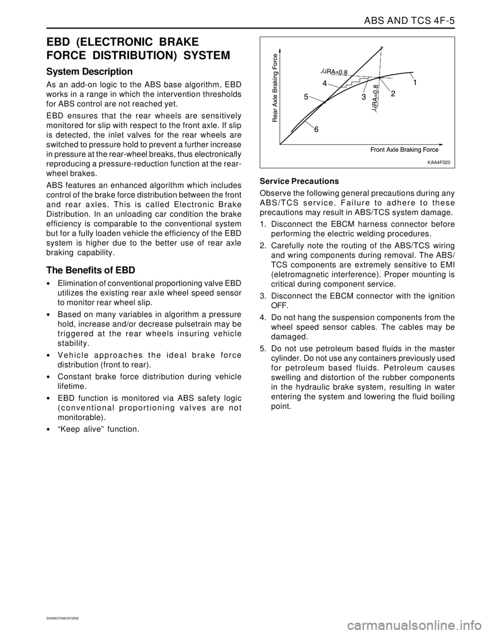
As an add-on logic to the ABS base algorithm, EBD
works in a range in which the intervention thresholds
for ABS control are not reached yet.
EBD ensures that the rear wheels are sensitively
monitored for slip with respect to the front axle. If slip
is detected, the inlet valves for the rear wheels are
switched to pressure hold to prevent a further increase
in pressure at the rear-wheel breaks, thus electronically
reproducing a pressure-reduction function at the rear-
wheel brakes.
ABS features an enhanced algorithm which includes
control of the brake force distribution between the front
and rear axles. This is called Electronic Brake
Distribution. In an unloading car condition the brake
efficiency is comparable to the conventional system
but for a fully loaden vehicle the efficiency of the EBD
system is higher due to the better use of rear axle
braking capability.
The Benefits of EBD
Elimination of conventional proportioning valve EBD
utilizes the existing rear axle wheel speed sensor
to monitor rear wheel slip.
Based on many variables in algorithm a pressure
hold, increase and/or decrease pulsetrain may be
triggered at the rear wheels insuring vehicle
stability.
Vehicle approaches the ideal brake force
distribution (front to rear).
Constant brake force distribution during vehicle
lifetime.
EBD function is monitored via ABS safety logic
(conventional proportioning valves are not
monitorable).
“Keep alive” function.Service Precautions
Observe the following general precautions during any
ABS/TCS service. Failure to adhere to these
precautions may result in ABS/TCS system damage.
1. Disconnect the EBCM harness connector before
performing the electric welding procedures.
2. Carefully note the routing of the ABS/TCS wiring
and wring components during removal. The ABS/
TCS components are extremely sensitive to EMI
(eletromagnetic interference). Proper mounting is
critical during component service.
3. Disconnect the EBCM connector with the ignition
OFF.
4. Do not hang the suspension components from the
wheel speed sensor cables. The cables may be
damaged.
5. Do not use petroleum based fluids in the master
cylinder. Do not use any containers previously used
for petroleum based fluids. Petroleum causes
swelling and distortion of the rubber components
in the hydraulic brake system, resulting in water
entering the system and lowering the fluid boiling
point.
KAA4F020
Page 1019 of 2053
SSANGYONG MY2002
4F-36 ABS AND TCS
SELF-DIAGNOSTICS
Important: The electronic brake control module (EBCM)
turns the valve relay off when a diagnostic trouble code
(DTC) is set. The scan tool will indicate that the valve
relay is off when it is used to monitor the data list. This
is normal and should not be considered a mal-function.
The EBCM performs system self-diagnostics and can
detect and often isolate system malfunctions. When it
detects a malfunction, the EBCM sets a DTC that repre
sents the malfunction, turns on the ABS and/or the
TCS indicators in most instances, and may disable the
ABS and/or the TCS functions, as necessary, for the
duration of the ignition cycle.
Once each ignition cycle, the EBCM performs an auto-
matic test when the vehicle reaches 2.75 km/h (1.7
mph). In the course of this test, the system cycles
each valve solenoid and the pump motor, along with
the necessary relays, to check component operation.
If the EBCM detects any malfunctions, it will set a
DTC as described above.
DISPLAYING DTCs
Tools Required
Scan Tool
DTCs can be read through the use of the scan tool.
CLEARING DTCs
Tools Required
Scan Tool
The diagnostic trouble codes (DTCs) in the electronic
brake control module (EBCM) memory are erased in
one of two ways:
Use the scan tool “Clear DTCs” selection.
After 249 DTC-free ignition cycles.
These two methods are detailed below. Be sure to verify
the proper system operation and, the absence of DTCs
when the clearing procedure is completed.The EBCM will not permit DTC clearing until all DTCs
have been displayed. Also, DTCs cannot be cleared
by disconnecting the EBCM, disconnecting the battery
cables, or turning the ignition switch to LOCK.
Scan Tool Method
The scan tool can clear ABS/TCS system DTCs using
the mass storage cartridge.
1. Install the scan tool and the mass storage
cartridge.
2. Select “Fault Memory”.
3. Select “Clear Fault Memory”.
Clearing the fault memory cannot reset a valve relay
which was shut down when the fault was recognized.
Changes are possible only after the fault has been elimi-
nated and the next ignition cycle has begun.
Ignition Cycle Default
A DTC is erased from memory after 249 ignition cycles
without any reappearance of that malfunction.
INTERMITTENTS AND POOR
CONNECTIONS
As with most electronic systems, intermittent malfunc
tions may be difficult to diagnose accurately. The follow-
ing is a method to try to isolate an intermittent
malfunction, especially in wheel speed circuitry.
If an ABS malfunction occurs, the ABS indicator will
illuminate during the ignition cycle in which the
malfunction was detected. If it is an intermittent problem
which seems to have corrected itself (ABS indicator
OFF), a history DTC will be stored. Also stored will be
the history data of the DTC at the time the malfunction
occurred. Use the scan tool modular diagnostic system
to read ABS history data.
Most intermittents are caused by faulty electrical con
nections or wiring, although a sticking relay or solenoid
can occasionally be at fault.