engine SSANGYONG KORANDO 1997 Service Repair Manual
[x] Cancel search | Manufacturer: SSANGYONG, Model Year: 1997, Model line: KORANDO, Model: SSANGYONG KORANDO 1997Pages: 2053, PDF Size: 88.33 MB
Page 250 of 2053

M162 ENGINE CONTROLS 1F1 -- 87
D AEW OO M Y_2000
BLANK
Page 251 of 2053
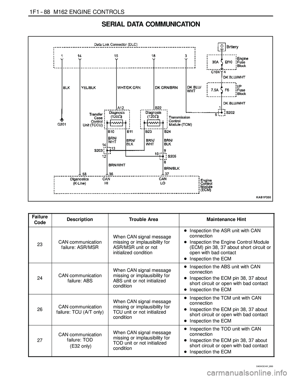
1F1 -- 88 M162 ENGINE CONTROLS
D AEW OO M Y_2000
SERIAL DATA COMMUNICATION
KAB1F350
Failure
CodeDescriptionTrouble AreaMaintenance Hint
23CAN communication
failure: ASR/MSR
When CAN signal message
missing or implausibility for
ASR/MSR unit or not
initialized condition
DInspection the ASR unit with CAN
connection
DInspection the Engine Control Module
(ECM) pin 38, 37 about short circuit or
open with bad contact
DInspection the ECM
24CAN communication
failure: ABS
When CAN signal message
missing or implausibility for
ABS unit or not initialized
conditionDInspection the ABS unit with CAN
connection
DInspection the ECM pin 38, 37 about
short circuit or open with bad contact
DInspection the ECM
26CAN communication
failure: TCU (A/T only)
When CAN signal message
missing or implausibility for
TCU unit or not initialized
conditionDInspection the TCM unit with CAN
connection
DInspection the ECM pin 38, 37 about
short circuit or open with bad contact
DInspection the ECM
27
CAN communication
failure: TOD
(E32 only)When CAN signal message
missing or implausibility for
TOD unit or not initialized
conditionDInspection the TOD unit with CAN
connection
DInspection the ECM pin 38, 37 about
short circuit or open with bad contact
DInspection the ECM
Page 252 of 2053
M162 ENGINE CONTROLS 1F1 -- 89
D AEW OO M Y_2000
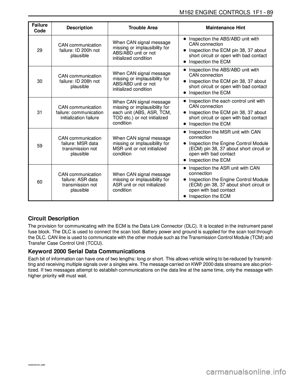
Failure
CodeDescriptionTrouble AreaMaintenance Hint
29
CAN communication
failure: ID 200h not
plausibleWhen CAN signal message
missing or implausibility for
ABS/ABD unit or not
initialized conditionDInspection the ABS/ABD unit with
CAN connection
DInspection the ECM pin 38, 37 about
short circuit or open with bad contact
DInspection the ECM
30
CAN communication
failure: ID 208h not
plausibleWhen CAN signal message
missing or implausibility for
ABS/ABD unit or not
initialized conditionDInspection the ABS/ABD unit with
CAN connection
DInspection the ECM pin 38, 37 about
short circuit or open with bad contact
DInspection the ECM
31
CAN communication
failure: communication
initialization failure
When CAN signal message
missing or implausibility for
each unit (ABS, ASR, TCM,
TOD etc.) or not initialized
conditionDInspection the each control unit with
CAN connection
DInspection the ECM pin 38, 37 about
short circuit or open with bad contact
DInspection the ECM
59
CAN communication
failure: MSR data
transmission not
plausibleWhen CAN signal message
missing or implausibility for
MSR unit or not initialized
condition
DInspection the MSR unit with CAN
connection
DInspection the Engine Control Module
(ECM) pin 38, 37 about short circuit or
open with bad contact
DInspection the ECM
60
CAN communication
failure: ASR data
transmission not
plausibleWhen CAN signal message
missing or implausibility for
ASR unit or not initialized
condition
DInspection the ASR unit with CAN
connection
DInspection the Engine Control Module
(ECM) pin 38, 37 about short circuit or
open with bad contact
DInspection the ECM
Circuit Description
The provision for communicating with the ECM is the Data Link Connector (DLC). It is located in the instrument panel
fuse block. The DLC is used to connect the scan tool. Battery power and ground is supplied for the scan tool through
the DLC. CAN line is used to communicate with the other module such as the Transmission Control Module (TCM) and
Transfer Case Control Unit (TCCU).
Keyword 2000 Serial Data Communications
Each bit of information can have one of two lengths: long or short. This allows vehicle wiring to be reduced by transmit-
ting and receiving multiple signals over a singles wire. The message carried on KWP 2000 data streams are also priori-
tized. If two messages attempt to establish communications on the data line at the same time, only the message with
higher prioritywill must wait.
Page 253 of 2053
1F1 -- 90 M162 ENGINE CONTROLS
D AEW OO M Y_2000
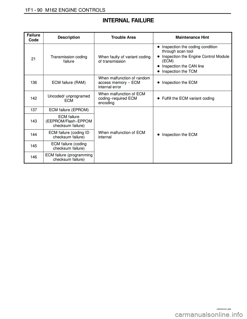
INTERNAL FAILURE
Failure
CodeDescriptionTrouble AreaMaintenance Hint
21Transmission coding
failureWhen faulty of variant coding
of transmission
DInspection the coding condition
through scan tool
DInspection the Engine Control Module
(ECM)
DInspection the CAN line
DInspection the TCM
136ECM failure (RAM)
When malfunction of random
access memory -- ECM
internal error
DInspection the ECM
142Uncoded/ unprogramed
ECMWhen malfunction of ECM
coding-- required ECM
encoding
DFulfill the ECM variant coding
137ECM failure (EPROM)
143
ECM failure
(EEPROM/Flash -- EPPOM
checksum failure)
144ECM failure (coding ID
checksum failure)When malfunction of ECM
internalDInspection the ECM
145ECM failure (coding
checksum failure)
146ECM failure (programming
checksum failure)
Page 254 of 2053

M162 ENGINE CONTROLS 1F1 -- 91
D AEW OO M Y_2000
BLANK
Page 255 of 2053
1F1 -- 92 M162 ENGINE CONTROLS
D AEW OO M Y_2000
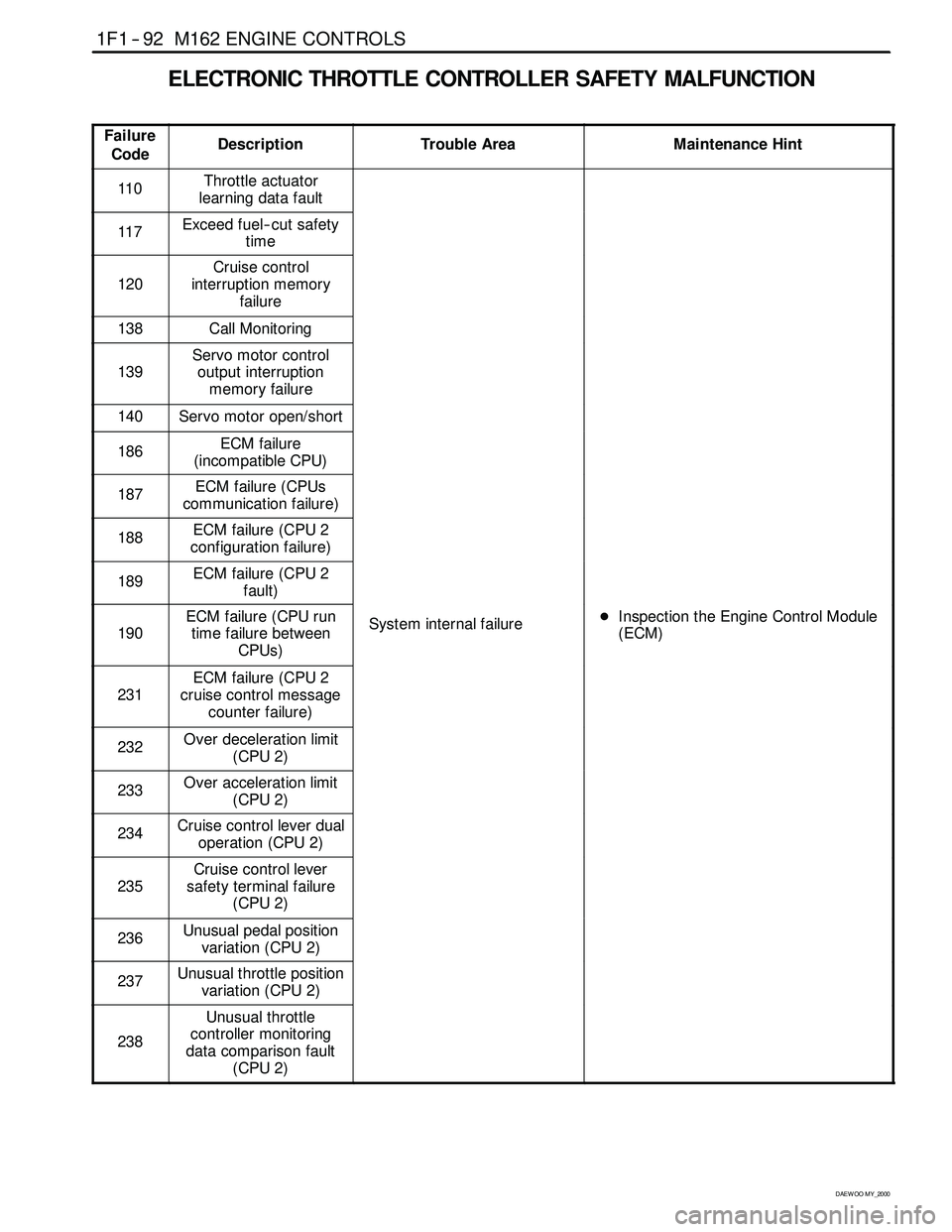
ELECTRONIC THROTTLE CONTROLLER SAFETY MALFUNCTION
Failure
CodeDescriptionTrouble AreaMaintenance Hint
110Throttle actuator
learning data fault
117Exceed fuel-- cut safety
time
120
Cruise control
interruption memory
failure
138Call Monitoring
139
Servo motor control
output interruption
memory failure
140Servo motor open/short
186ECM failure
(incompatible CPU)
187ECM failure (CPUs
communication failure)
188ECM failure (CPU 2
configuration failure)
189ECM failure (CPU 2
fault)
190
ECM failure (CPU run
time failure between
CPUs)System internal failureDInspection the Engine Control Module
(ECM)
231
ECM failure (CPU 2
cruise control message
counter failure)
232Over deceleration limit
(CPU 2)
233Over acceleration limit
(CPU 2)
234Cruise control lever dual
operation (CPU 2)
235
Cruise control lever
safety terminal failure
(CPU 2)
236Unusual pedal position
variation (CPU 2)
237Unusual throttle position
variation (CPU 2)
238
Unusual throttle
controller monitoring
data comparison fault
(CPU 2)
Page 256 of 2053
M162 ENGINE CONTROLS 1F1 -- 93
D AEW OO M Y_2000
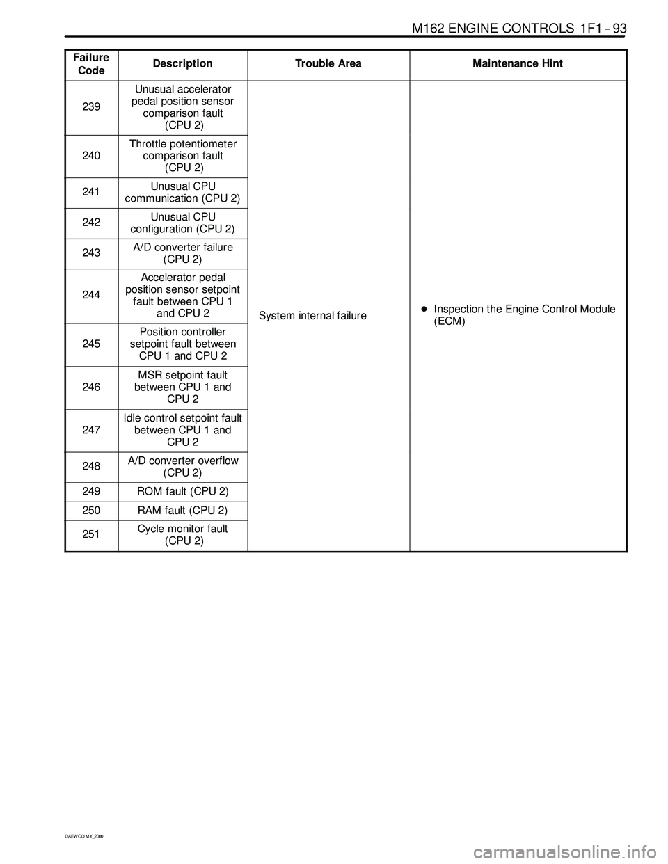
Failure
CodeDescriptionTrouble AreaMaintenance Hint
239
Unusual accelerator
pedal position sensor
comparison fault
(CPU 2)
240
Throttle potentiometer
comparison fault
(CPU 2)
241Unusual CPU
communication (CPU 2)
242Unusual CPU
configuration (CPU 2)
243A/D converter failure
(CPU 2)
244
Accelerator pedal
position sensor setpoint
fault between CPU 1
and CPU 2
System internal failureDInspection the Engine Control Module
(ECM)
245
Position controller
setpoint fault between
CPU 1 and CPU 2
y(ECM)
246
MSR setpoint fault
between CPU 1 and
CPU 2
247
Idle control setpoint fault
between CPU 1 and
CPU 2
248A/D converter overflow
(CPU 2)
249ROM fault (CPU 2)
250RAM fault (CPU 2)
251Cycle monitor fault
(CPU 2)
Page 257 of 2053
1F1 -- 94 M162 ENGINE CONTROLS
D AEW OO M Y_2000
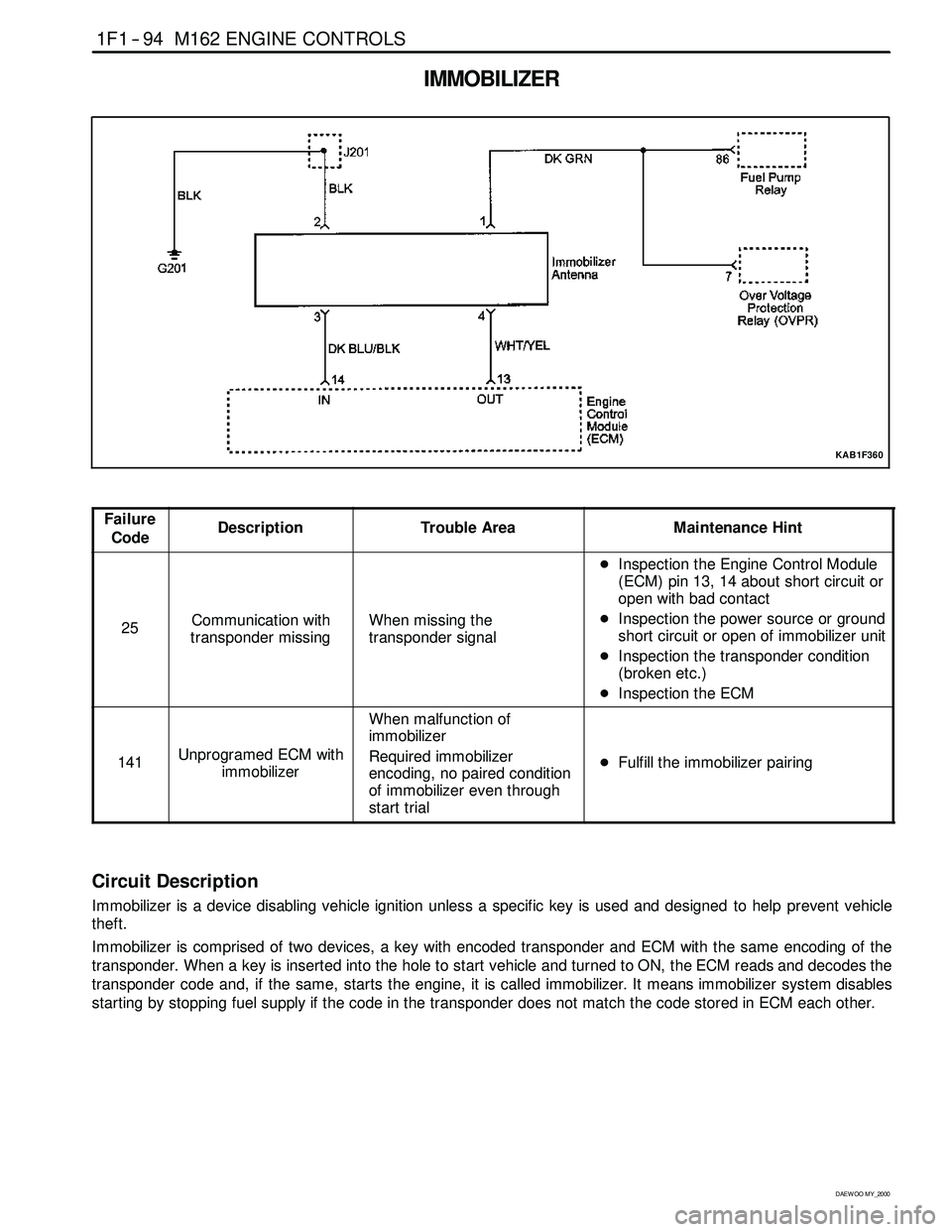
IMMOBILIZER
KAB1F360
Failure
CodeDescriptionTrouble AreaMaintenance Hint
25Communication with
transponder missingWhen missing the
transponder signal
DInspection the Engine Control Module
(ECM) pin 13, 14 about short circuit or
open with bad contact
DInspection the power source or ground
short circuit or open of immobilizer unit
DInspection the transponder condition
(broken etc.)
DInspection the ECM
141Unprogramed ECM with
immobilizer
When malfunction of
immobilizer
Required immobilizer
encoding, no paired condition
of immobilizer even through
start trial
DFulfill the immobilizer pairing
Circuit Description
Immobilizer is a device disabling vehicle ignition unless a specific key is used and designed to help prevent vehicle
theft.
Immobilizer is comprised of two devices, a key with encoded transponder and ECM with the same encoding of the
transponder. When a key is inserted into the hole to start vehicle and turned to ON, the ECM reads and decodes the
transponder code and, if the same, starts the engine, it is called immobilizer. It means immobilizersystem disables
starting by stopping fuel supply if the code in the transponder does not match the code stored in ECM each other.
Page 258 of 2053
M162 ENGINE CONTROLS 1F1 -- 95
D AEW OO M Y_2000
MAINTENANCE AND REPAIR
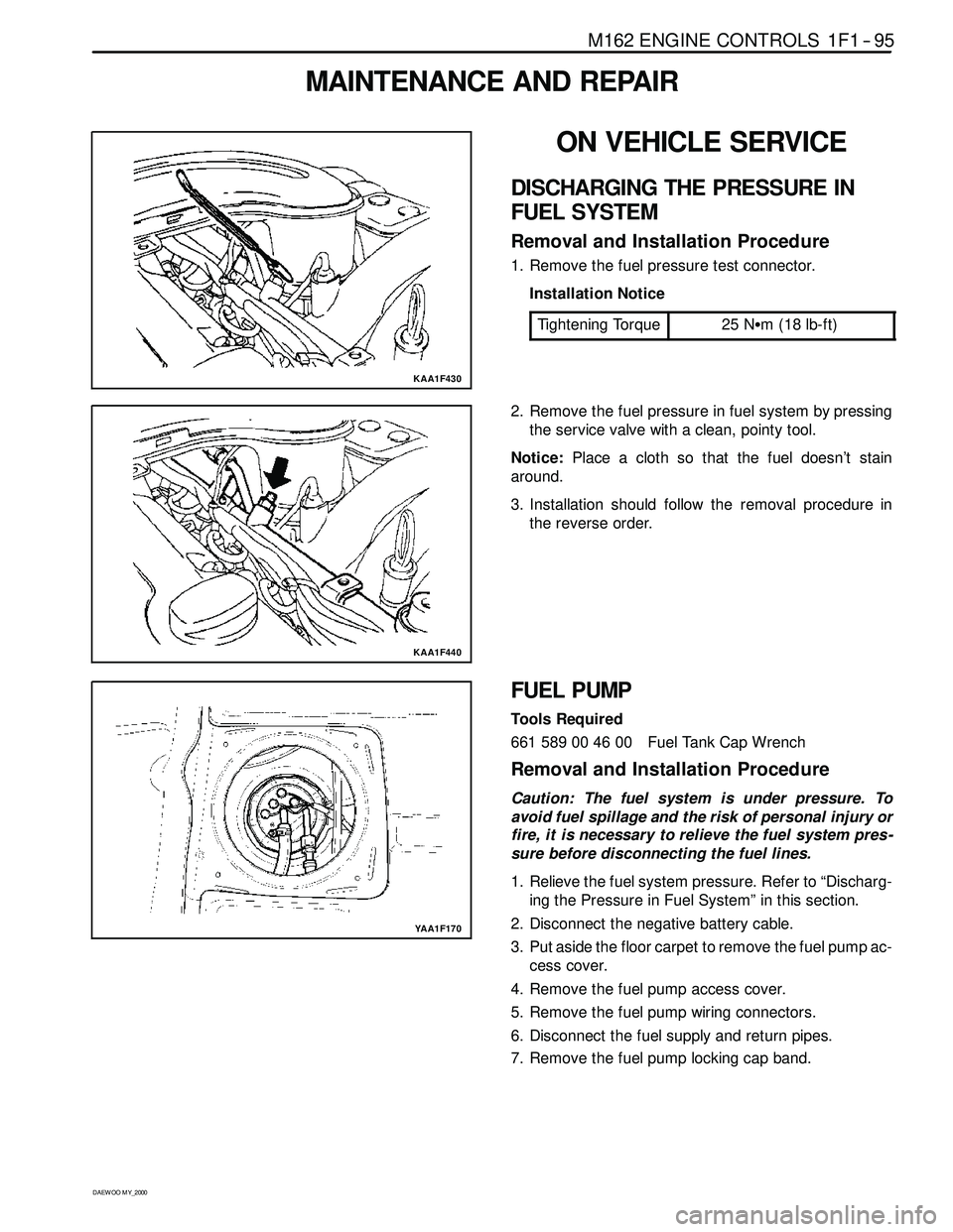
KAA1F430
ON VEHICLE SERVICE
DISCHARGING THE PRESSURE IN
FUEL SYSTEM
Removal and Installation Procedure
1. Remove the fuel pressure test connector.
Installation Notice
Tightening Torque
25 NSm (18 lb-ft)
KAA1F440
2. Remove the fuel pressure in fuel system by pressing
the service valve with a clean, pointy tool.
Notice:Place a cloth so that the fuel doesn’t stain
around.
3. Installation should follow the removal procedure in
the reverse order.
YAA1F170
FUEL PUMP
Tools Required
661 589 00 46 00 Fuel Tank Cap Wrench
Removal and Installation Procedure
Caution: The fuel system is under pressure. To
avoid fuel spillage and the risk of personal injury or
fire, it is necessary to relieve the fuel system pres -
sure before disconnecting the fuel lines.
1. Relieve the fuel system pressure. Refer to “Discharg-
ing the Pressure in Fuel System” in this section.
2. Disconnect the negative battery cable.
3. Put aside the floor carpet to remove the fuel pump ac-
cess cover.
4. Remove the fuel pump access cover.
5. Remove the fuel pump wiring connectors.
6. Disconnect the fuel supply and return pipes.
7. Remove the fuel pump locking cap band.
Page 259 of 2053
1F1 -- 96 M162 ENGINE CONTROLS
D AEW OO M Y_2000
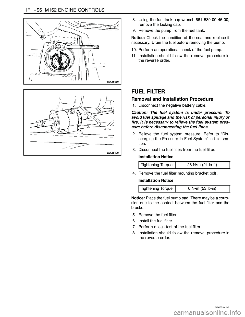
YAA1F550
8. Using the fuel tank cap wrench 661 589 00 46 00,
remove the locking cap.
9. Remove the pump from the fuel tank.
Notice:Check the condition of the seal and replace if
necessary. Drain the fuel before removing the pump.
10. Perform an operational check of the fuel pump.
11. Installation should follow the removal procedure in
the reverse order.
YAA1F190
FUEL FILTER
Removal and Installation Procedure
1. Disconnect the negative battery cable.
Caution: The fuel system is under pressure. To
avoid fuel spillage and the risk of personal injury or
fire, it is necessary to relieve the fuel system pres -
sure before disconnecting the fuel lines.
2. Relieve the fuel system pressure. Refer to “Dis-
charging the Pressure in Fuel System” in this sec-
tion.
3. Disconnect the fuel lines from the fuel filter.
Installation Notice
Tightening Torque
28 NSm (21 lb-ft)
4. Remove the fuel filter mounting bracket bolt .
Installation Notice
Tightening Torque
6NSm (53 lb-in)
Notice:Place the fuel pump pad. There may be a corro-
sion due to the contact between the fuel filter and the
bracket.
5. Remove the fuel filter.
6. Install the fuel filter.
7. Perform a leak test of the fuel filter.
8. Installation should follow the removal procedure in
the reverse order.