cap SSANGYONG KORANDO 1997 Service Owner's Manual
[x] Cancel search | Manufacturer: SSANGYONG, Model Year: 1997, Model line: KORANDO, Model: SSANGYONG KORANDO 1997Pages: 2053, PDF Size: 88.33 MB
Page 108 of 2053

1B1 -- 82 M162 ENGINE MECHANICAL
D AEW OO M Y_2000
Installation Procedure
1. Check the piston ring gap and apply the engine oil to
the piston pin and the connecting rod bushing.
2. Connect the piston and the connecting rod by press-
ing in the piston pin (6) and install the snap ring to the
groove.
3. Clean the cylinder bore, connecting rod bearing jour-
nal, connecting rod bearing shell and the piston and
coat them with engine oil.
4. Install the piston ring.
5. Install the piston so that the arrow on the piston head
faces to the forward of the vehicle.
6. After aligning the connecting rod and the bearing cap
mark (// or a number), tighten the bolts.
Installation Notice
TighteningTorque1st step: 40 NSm (30 lb-ft)TighteningTorque2nd step: 90°
Apply the engine oil to the bearing cap upper and low-
er bearing shells.
7. Check if the crankshaft rotates without any trouble by
rotating it.
Page 109 of 2053
M162 ENGINE MECHANICAL 1B1 -- 83
D AEW OO M Y_2000
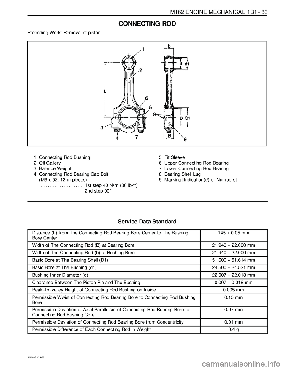
CONNECTING ROD
Preceding Work: Removal of piston
1 Connecting Rod Bushing
2 Oil Gallery
3 Balance Weight
4 Connecting Rod Bearing Cap Bolt
(M9 x 52, 12 m pieces)
1ststep40NSm (30 lb-ft) ..................
2nd step 90°5 Fit Sleeve
6 Upper Connecting Rod Bearing
7 Lower Connecting Rod Bearing
8 Bearing Shell Lug
9 Marking [Indication(//) or Numbers]
ServiceDataStandard
Distance (L) from The Connecting Rod Bearing Bore Center to The Bushing
Bore Center145±0.05 mm
Width of The Connecting Rod (B) at Bearing Bore21.940 -- 22.000 mm
Width of The Connecting Rod (b) at Bushing Bore21.940 -- 22.000 mm
Basic Bore at The Bearing Shell (D1)51.600 -- 51.614 mm
Basic Bore at The Bushing (d1)24.500 -- 24.521 mm
Bushing Inner Diameter (d)22.007 -- 22.013 mm
Clearance Between The Piston Pin and The Bushing0.007 -- 0.018 mm
Peak -- to-- valley Height of Connecting Rod Bushing on Inside0.005 mm
Permissible Wwist of Connecting Rod Bearing Bore to Connecting Rod Bushing
Bore0.15 mm
Permissible Deviation of Axial Paralleism of Connecting Rod Bearing Bore to
Connecting Rod Bushing Core0.07 mm
Permissible Deviation of Connecting Rod Bearing Bore from Concentricity0.01 mm
Permissible Difference of Each Connecting Rod in Weight0.4 g
Page 110 of 2053

1B1 -- 84 M162 ENGINE MECHANICAL
D AEW OO M Y_2000
Inspection
1. Measure the basic bore of the connecting rod bear-
ing.
Notice:If the basic bore exceeds the value of
51.614mm, replace the bearing or check the connecting
rod.
2. Check connecting rod bolts.
Length When New (L)
51.7 -- 52 mm
Max. Length (L)52.9 mm
Tightening Torque
1st step: 40 NSm
(30 lb-ft)
TighteningTorque
2nd step: 90°
Notice:If the length exceeds max. length, replace it.
3. Check the assembly mark(indication//or number:ar-
row) of the connecting rods and the bearing cap when
installing.
Notice
DMake sure it doesn’t exceed over 4g with other con-
necting rods when replacing the connecting rods.
DCheck if the connecting rod and the bearing cap are
accurately seated on the groove when replacing the
bearing.
Page 113 of 2053
M162 ENGINE MECHANICAL 1B1 -- 87
D AEW OO M Y_2000
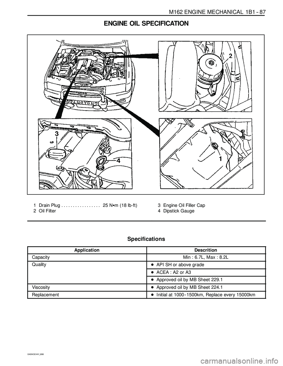
ENGINE OIL SPECIFICATION
1 Drain Plug 25 NSm (18 lb-ft) .................
2 Oil Filter3 Engine Oil Filler Cap
4 Dipstick Gauge
Specifications
ApplicationDescrition
CapacityMin : 6.7L, Max : 8.2L
QualityDAPI SH or above gradey
DACEA : A2 or A3
DApproved oil by MB Sheet 229.1
ViscosityDApproved oil by MB Sheet 224.1
ReplacementDInitial at 1000-- 1500km, Replace every 15000km
Page 116 of 2053

1B1 -- 90 M162 ENGINE MECHANICAL
D AEW OO M Y_2000
ENGINE OIL AND OIL FILTER
ELEMENT
Tools Required
103 589 02 09 00 Oil Filter Remover
Replacement Procedure
1. Install the oil filter remover 103 589 02 09 00 on the oil
filter cover.
Notice:Make the screw cover removable by tightening
the bolt at the side of the oil filter remover 103 589 02 09
00.
2. Install the wrench to the upper bolt in the oil filter re-
mover 103 589 02 09 00 and remove the oil cover by
turning it.
3. Remove the oil filter element.
Notice:Work with a cloth under the vehicle when re-
moving the oil filter element not to drain the oil.
4. Remove the drain plug (arrow) and drain the engine
oil.
Notice:Leave the oil filler cap open to ease theengine
oil discharge.
5. Tighten the engine oil drain plug after cleaning it.
Installation Notice
Tightening Torque
25 NSm (18 lb-ft)
Replace the seal washer with new one.
6. Replace the O -- ring in the oil filter cover with new one.
Notice:Apply the engine oil to the O -- ring.
7. Insert new oil filter element into the oil filter housing.
Page 117 of 2053
M162 ENGINE MECHANICAL 1B1 -- 91
D AEW OO M Y_2000
8. Temporarily tighten the oil filter cover. Install the oil
filter remover 103 589 02 09 00, and then complete-
ly tighten it.
Installation Notice
Tightening Torque
25 NSm (18 lb-ft)
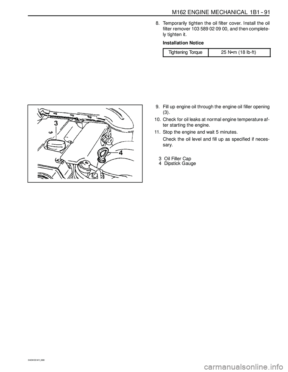
9. Fill up engine oil through the engine oil filler opening
(3).
10. Check for oil leaks at normal engine temperature af-
ter starting the engine.
11. Stop the engine and wait 5 minutes.
Check the oil level and fill up as specified if neces-
sary.
3 Oil Filler Cap
4 Dipstick Gauge
Page 138 of 2053
1D1 -- 2 M162 ENGINE COOLING
D AEW OO M Y_2000
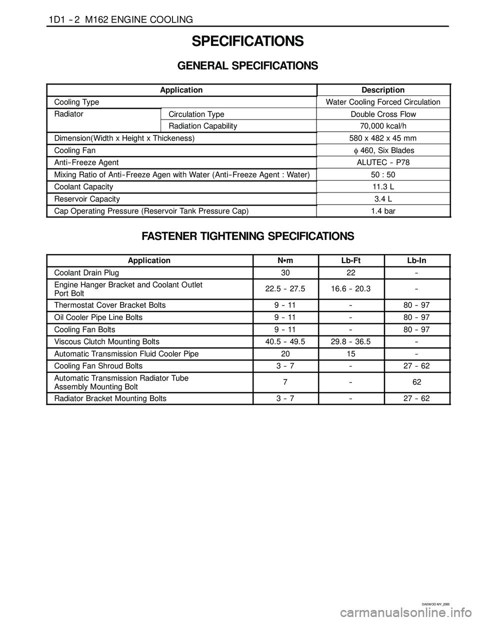
SPECIFICATIONS
GENERAL SPECIFICATIONS
ApplicationDescription
Cooling TypeWater Cooling Forced Circulation
RadiatorCirculation TypeDouble Cross Flow
Radiation Capability70,000 kcal/h
Dimension(Width x Height x Thickeness)580 x 482 x 45 mm
Cooling Fanφ460, Six Blades
Anti-- Freeze AgentALUTEC -- P78
Mixing Ratio of Anti-- Freeze Agen with Water (Anti-- Freeze Agent : Water)50 : 50
Coolant Capacity11. 3 L
Reservoir Capacity3.4 L
Cap Operating Pressure (Reservoir Tank Pressure Cap)1.4 bar
FASTENER TIGHTENING SPECIFICATIONS
ApplicationNSmLb-FtLb-In
Coolant Drain Plug3022--
Engine Hanger Bracket and Coolant Outlet
Port Bolt22.5 -- 27.516.6 -- 20.3--
Thermostat Cover Bracket Bolts9--11--80 -- 97
Oil Cooler Pipe Line Bolts9--11--80 -- 97
Cooling Fan Bolts9--11--80 -- 97
Viscous Clutch Mounting Bolts40.5 -- 49.529.8 -- 36.5--
Automatic Transmission Fluid Cooler Pipe2015--
Cooling Fan Shroud Bolts3--7--27 -- 62
Automatic Transmission Radiator Tube
Assembly Mounting Bolt7--62
Radiator Bracket Mounting Bolts3--7--27 -- 62
Page 140 of 2053

1D1 -- 4 M162 ENGINE COOLING
D AEW OO M Y_2000
DIAGNOSIS
SYSTEM LEAKAGE TEST
Tools Required
124 589 15 21 00 Tester
Test Procedure
1. Loosen the cap a little and release pressure and re-
move the cap.
Notice:For the risk of scalding, cap must not be opened
unless the coolant temperature is below 90°C.
2. Fill coolant up to upper edge (arrow) of reservoir.
3. Connect the special tool to the reservoir filler cap and
apply 1.4 bar of pressure.
Tester 124 589 15 21 00
4. If the pressure on the tester drops, check leakage at
the all coolant hoses and pipes and each connec-
tions. Replace or retighten if necessary.
Page 141 of 2053

M162 ENGINE COOLING 1D1 -- 5
D AEW OO M Y_2000
MAINTENANCE AND REPAIR
ON-VEHICLE SERVICE
COOLANT DRAIN AND FILL UP
Draning & Filling up Procedure
1. Loosen the cap a little and release pressure and re-
move the cap.
Notice:For the risk of scalding, the cap must not be
opened unless the coolant temperature is below 90°C.
2. Loosen the radiator lower drain cock and drain the
coolant.
Notice:Collect the coolant by using a proper container.
3. Drain the coolant from the crankcase by inserting a
hose (dia. 14mm) onto the drain bolt on the side of
crankcase (exhaust manifold) and by loosening the
plug.
Notice
DJust loosen the drain plug to drain the coolant and do
not remove the plug completely.
DCollect the coolant by using the proper container.
4. After complete draining of the coolant, remove the
hose connector to drain plug and reinstall the drain
plug.
Installation Notice
Tightening Torque
30 NSm (22 lb-ft)
5. Tighten the radiator lower drain cock.
Page 154 of 2053

1E 1 -- 2 M162 ENGINE ELECTRICAL
D AEW OO M Y_2000
SPECIFICATIONS
GENERATOR SPECIFICATIONS
ApplicationDescription
Current11 5 A
Output Voltage12 -- 14 v
Resistance Between Rotor Core and Slip Ring∞Ω
STARTER SPECIFICATIONS
ApplicationDescription
Output Power1.8 kw
Voltage12 v
BATTERY SPECIFICATIONS
ApplicationDescription
Capacity90 AH
Max. Tolerance Between Cells≥0.04
Specific Gravity≥1.24
FASTER TIGHTENING SPECIFICATIONS
ApplicationNSmLb-FtLb-In
Generator Terminal B+Nut14 -- 1810 -- 13--
Generator Terminal D+Nut4--5--35 -- 44
Generator Mounting Bolt2518--
Battery Cable Nut on Starting Motor12 -- 159--11--
Electric Wire Nut on Starting Motor6--7--53 -- 62
Starting Motor Mounting Bolt35 -- 4826 -- 35--
Battery Mounting Bracket Nut12 -- 189--13--
Battery Negative Cable12 -- 189--13--
Battery Positive Cable12 -- 189--13--
Spark Plug Cover Bolt9--11--80 -- 97
Ignition Cable Bolt9--11--80 -- 97
Spark plug20 -- 3015 -- 22--