engine SSANGYONG KORANDO 1997 Service Owner's Guide
[x] Cancel search | Manufacturer: SSANGYONG, Model Year: 1997, Model line: KORANDO, Model: SSANGYONG KORANDO 1997Pages: 2053, PDF Size: 88.33 MB
Page 40 of 2053
1B1 -- 8 M162 ENGINE MECHANICAL
D AEW OO M Y_2000
Removal & Installation Procedure
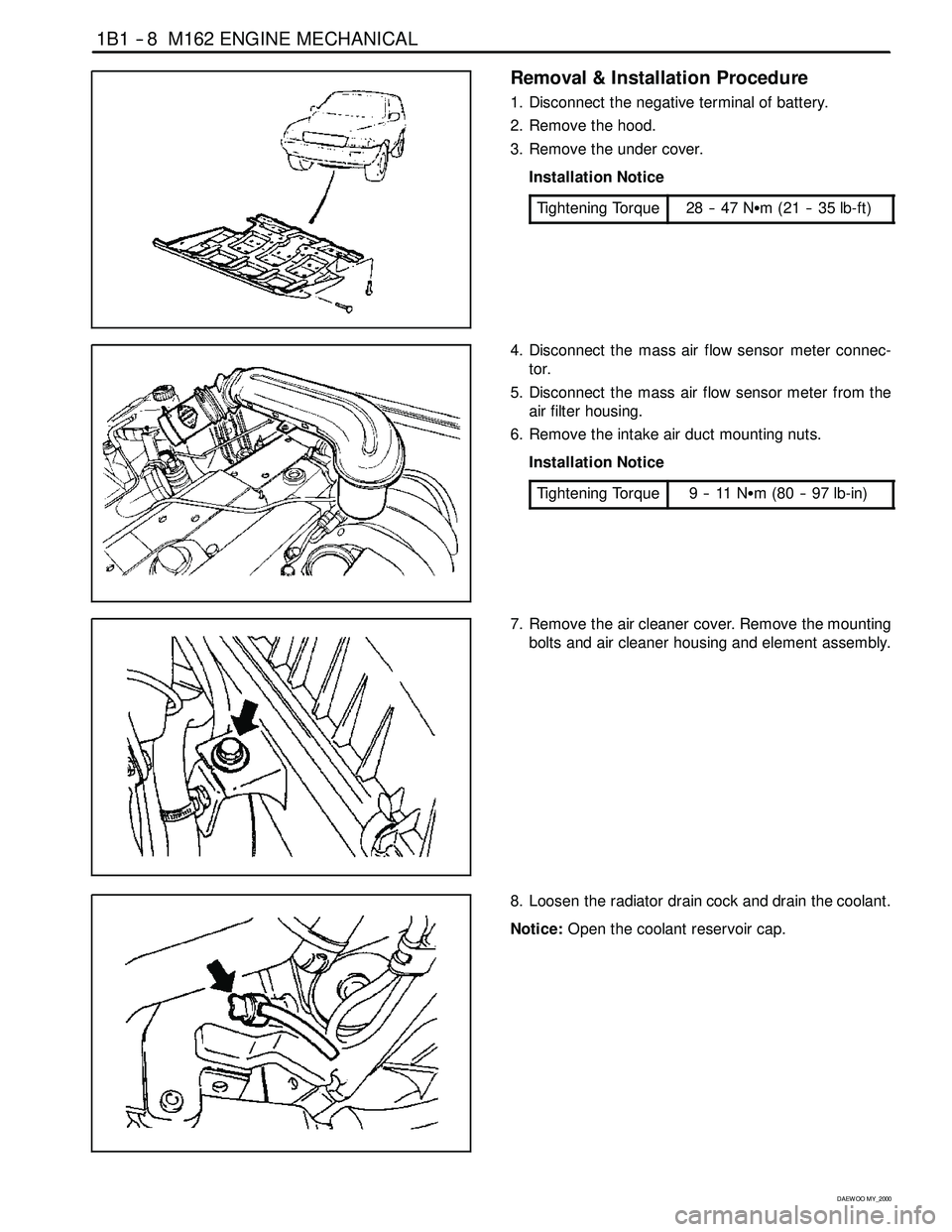
1. Disconnect the negative terminal of battery.
2. Remove the hood.
3. Remove the under cover.
Installation Notice
Tightening Torque
28 -- 47 NSm (21 -- 35 lb-ft)
4. Disconnect the mass air flow sensor meter connec-
tor.
5. Disconnect the mass air flow sensor meter from the
air filter housing.
6. Remove the intake air duct mounting nuts.
Installation Notice
Tightening Torque
9--11NSm (80 -- 97 lb-in)
7. Remove the air cleaner cover. Remove the mounting
bolts and air cleaner housing and element assembly.
8. Loosen the radiator drain cock and drain the coolant.
Notice:Open the coolant reservoir cap.
Page 41 of 2053
M162 ENGINE MECHANICAL 1B1 -- 9
D AEW OO M Y_2000
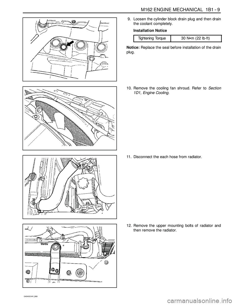
9. Loosen the cylinder block drain plug and then drain
the coolant completely.
Installation Notice
Tightening Torque
30 NSm (22 lb-ft)
Notice:Replace the seal before installation of the drain
plug.
10. Remove the cooling fan shroud. Refer toSection
1D1, Engine Cooling.
11. Disconnect the each hose from radiator.
12. Remove the upper mounting bolts of radiator and
then remove the radiator.
Page 42 of 2053

1B1 -- 10 M162 ENGINE MECHANICAL
D AEW OO M Y_2000
13. Remove the hydraulic pipe of power steering.
Notice:Completely drain the oil.
14. Discharge the refrigerant from A/C system, and dis-
connect the discharge pipe and suction pipe from
the compressor. Refer toSection 7B, Manual Con-
trol Heating, Ventilation, and Air Conditioning Sys -
tem.
15. Remove the fuel feed and return line.
Notice:Before removing the fuel lines, release the pres-
sure in the fuel system.
Installation Notice
Tightening Torque
21 -- 25 NSm (15 -- 18 lb-ft)
16. Disconnect the terminals from the generator.
Page 43 of 2053
M162 ENGINE MECHANICAL 1B1 -- 11
D AEW OO M Y_2000
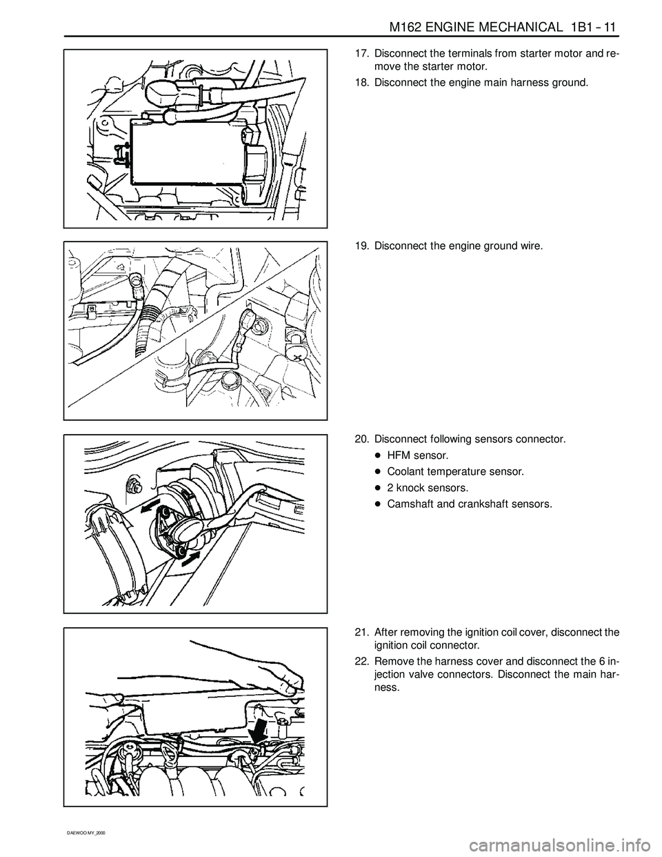
17. Disconnect the terminals from starter motor and re-
move the starter motor.
18. Disconnect the engine main harness ground.
19. Disconnect the engine ground wire.
20. Disconnect following sensors connector.
DHFM sensor.
DCoolant temperature sensor.
D2 knock sensors.
DCamshaft and crankshaft sensors.
21. After removing the ignition coil cover, disconnect the
ignition coil connector.
22. Remove the harness cover and disconnect the 6 in-
jection valve connectors. Disconnect the main har-
ness.
Page 44 of 2053
1B1 -- 12 M162 ENGINE MECHANICAL
D AEW OO M Y_2000
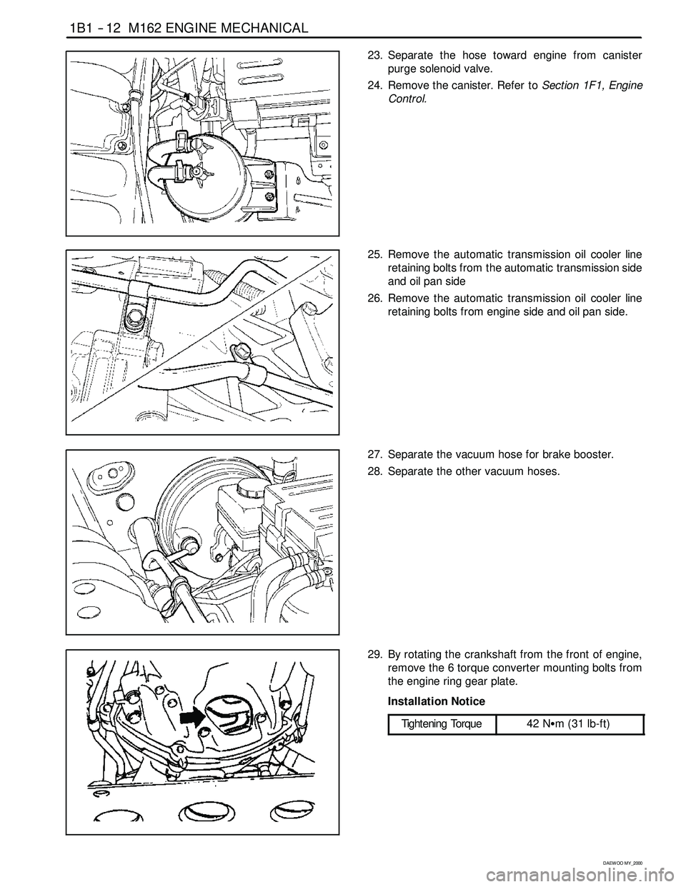
23. Separate the hose toward engine from canister
purge solenoid valve.
24. Remove the canister. Refer toSection 1F1, Engine
Control.
25. Remove the automatic transmission oil cooler line
retaining bolts from the automatic transmission side
and oil pan side
26. Remove the automatic transmission oil cooler line
retaining bolts from engine side and oil pan side.
27. Separate the vacuum hose for brake booster.
28. Separate the other vacuum hoses.
29. By rotating the crankshaft from the front of engine,
remove the 6 torque converter mounting bolts from
the engine ring gear plate.
Installation Notice
Tightening Torque
42 NSm (31 lb-ft)
Page 45 of 2053

M162 ENGINE MECHANICAL 1B1 -- 13
D AEW OO M Y_2000
30. Remove the exhaust manifold and exhaust pipe.
Installation Notice
Tightening Torque
30 NSm (22 lb-ft)
31. Remove the transmission.Refer to Section 5A, Au-
tomatic Transmission.
32. Install a chain to the bracket of engine, by using a
hoist or crane.
33. Remove the engine mount nuts.
Installation Notice
Tightening Torque
70 NSm (52 lb-ft)
34. Carefully separate the engine assembly from the ve-
hicle.
35. Installation should follow the removal procedure in
the reverse order.
Page 46 of 2053
1B1 -- 14 M162 ENGINE MECHANICAL
D AEW OO M Y_2000
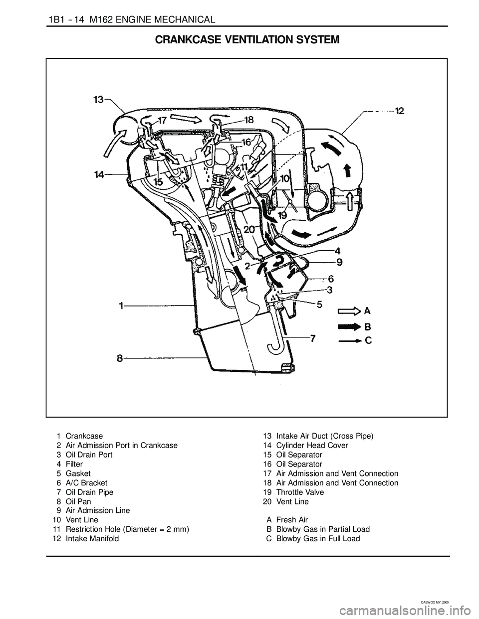
CRANKCASE VENTILATIONSYSTEM
1 Crankcase
2 Air Admission Port in Crankcase
3 Oil Drain Port
4 Filter
5 Gasket
6 A/C Bracket
7 Oil Drain Pipe
8OilPan
9 Air Admission Line
10 Vent Line
11 Restriction Hole (Diameter = 2 mm)
12 Intake Manifold13 Intake Air Duct (Cross Pipe)
14 Cylinder Head Cover
15 Oil Separator
16 Oil Separator
17 Air Admission and Vent Connection
18 Air Admission and Vent Connection
19 Throttle Valve
20 Vent Line
A Fresh Air
B Blowby Gas in Partial Load
C Blowby Gas in Full Load
Page 47 of 2053
M162 ENGINE MECHANICAL 1B1 -- 15
D AEW OO M Y_2000
Operation at Idling and Mid-Load
DIt show that the throttle valve (19) is closed or very
partially opened and the vacuum pressure in intake
manifold is high.
The blowby gas in the crankcase in partial load flows
into the intake manifold through the vent line (20) af-
ter passing the air conditioner bracket (6) and the fil-
ter (4). The air reentered into the intake manifoldwill
be dilluted on the flow through the restriction hole (11)
in the vent line (10).
The circulated engine oil is separated at the air condi-
tioner bracket (6) and then returns into the oil pan
through the drain pipe (7).
The vacuum pressure generated at the crankcase
sucks fresh air from intake air line (13) through the air
admission and vent connection (17,18).
The fresh air prevents engine oil from being contami-
nated and the air admission and vent connection
(17,18) is designed to control the rapid pressure
changes in intake air line (13).
Operation at Full-Load
DThe throttle valve (19) is fully opened.
All the blowby gases flow into the intake air duct (13)
after passing through the oil separator (15,16) of the
cylinder head cover (14) when fully loaded. This dil-
luted air will be supplied to the combustion chamber
through the intake manifold (12).
Page 48 of 2053

1B1 -- 16 M162 ENGINE MECHANICAL
D AEW OO M Y_2000
GENERATOR
1 Nut (M8) 22.5-- 27.5 NSm (16.6-- 20.3 lb-ft) .....
2 Bolt (M8 x 30, 3 pieces)
22.5-- 27.5 NSm (16.6-- 20.3 lb-ft) .............
3 Bolt (M8 x 40, 1 piece)
22.5-- 27.5 NSm (16.6-- 20.3 lb-ft) .............4 Bolt (M8 x 70, 1 piece)
22.5-- 27.5 NSm (16.6--20.3 lb-ft) .............
5 Bolt (M8 x 75, 1 piece)
22.5-- 27.5 NSm (16.6--20.3 lb-ft) .............
Removal & Installation Procedure
1. Remove the drive belt.
2. Remove the generator.
3. Unscrew the generator carrier bolts and remove the
carrier.
Installation Notice
Tightening Torque
25 NSm (18 lb-ft)
4. Installation should follow the removal procedure in
the reverse order.
Page 49 of 2053

M162 ENGINE MECHANICAL 1B1 -- 17
D AEW OO M Y_2000
ENGINE MOUNT
Removal & Installation Procedure
1. Unscrew the upper engine mount nuts and remove
the engine.
Installation Notice
Tightening Torque
70 NSm (52 lb-ft)
2. Unscrew the lower nuts.
Installation Notice
Tightening Torque
38 NSm (28 lb-ft)
3. Remove the hydraulic engine mounting insulator.
4. Installation should follow the removal procedure in
the reverse order.