SSANGYONG KORANDO 1997 Service Service Manual
KORANDO 1997
SSANGYONG
SSANGYONG
https://www.carmanualsonline.info/img/67/57502/w960_57502-0.png
SSANGYONG KORANDO 1997 Service Service Manual
Page 50 of 2053
1B1 -- 18 M162 ENGINE MECHANICAL
D AEW OO M Y_2000
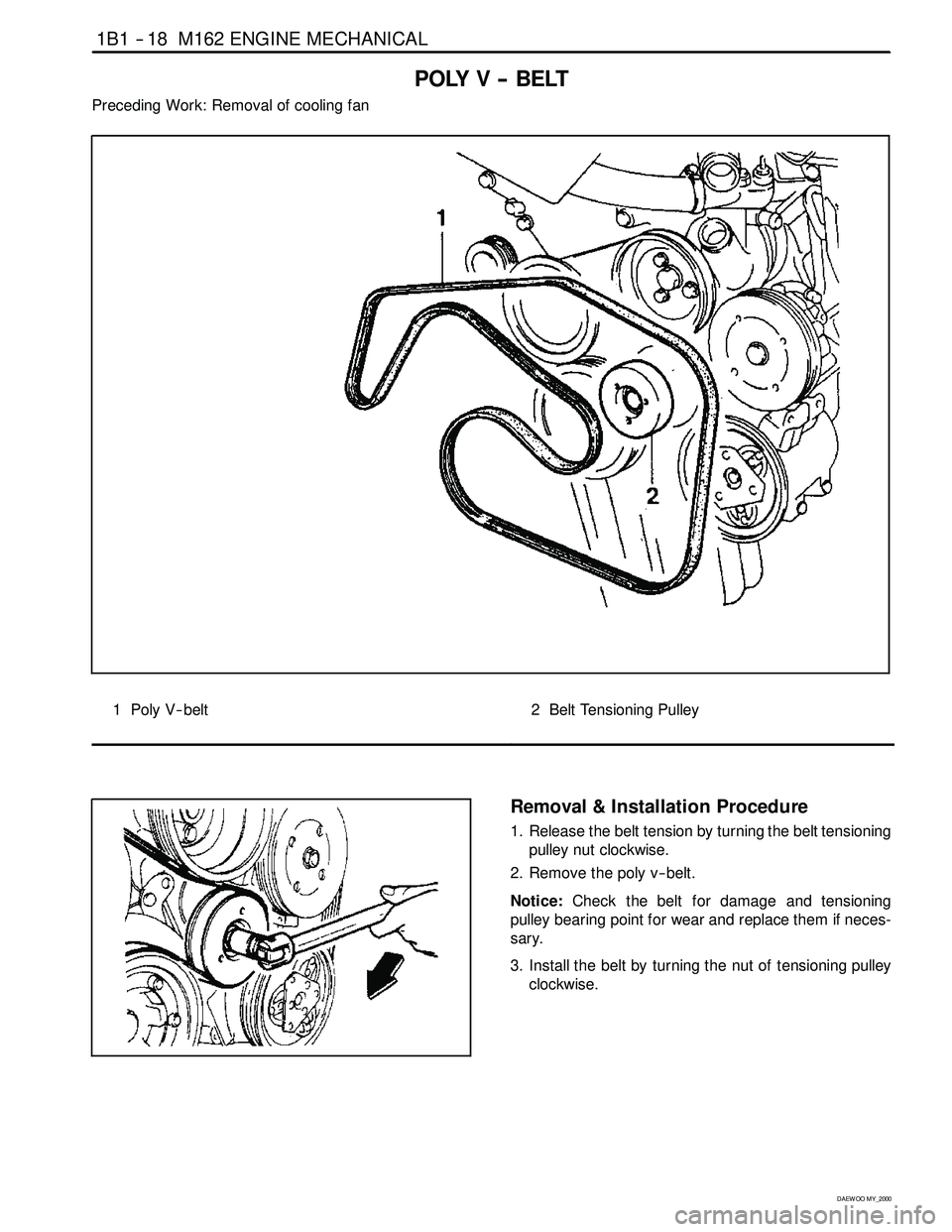
POLY V -- BELT
Preceding Work: Removal of cooling fan
1 Poly V-- belt2 Belt Tensioning Pulley
Removal & Installation Procedure
1. Release the belt tension by turning the belt tensioning
pulley nut clockwise.
2. Remove the poly v -- belt.
Notice:Check the belt for damage and tensioning
pulley bearing point for wear and replace them if neces-
sary.
3. Install the belt by turning the nut of tensioning pulley
clockwise.
Page 51 of 2053
M162 ENGINE MECHANICAL 1B1 -- 19
D AEW OO M Y_2000
Poly V - Belt Arrangement
1 Belt Tensioning Pulley
2 Crankshaft Belt Pulley
3 A/C Compressor Pulley
4 Cooling Fan Pulley5 Generator Pulley
6 Idler
7 Power Steering Pump Pulley
8 Cooling Fan and Water Pump Pulley
Page 52 of 2053
1B1 -- 20 M162 ENGINE MECHANICAL
D AEW OO M Y_2000
TENSIONING DEVICE
Preceding Work: Removal of poly v -- belt
1 Belt (L = 2245)
2 Bolt Combi (M8 x 14, 3 pieces) + Washer
22.5-- 27.5 NSm (16.6-- 20.3 lb-ft) .............3 Water Pump Pulley
4Nut
5 Tensioning Pulley
Page 53 of 2053
M162 ENGINE MECHANICAL 1B1 -- 21
D AEW OO M Y_2000
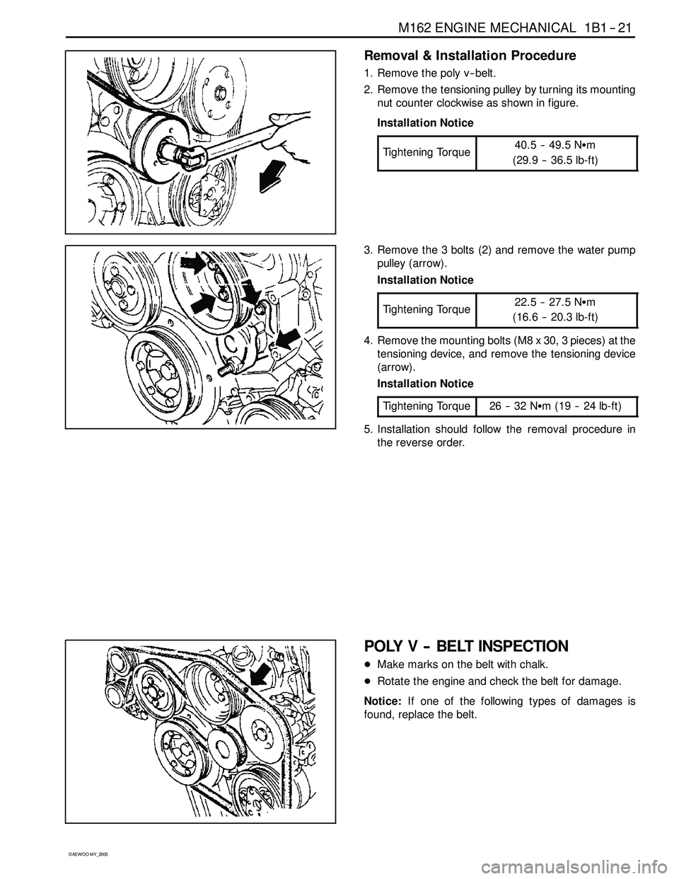
Removal & Installation Procedure
1. Remove the poly v -- belt.
2. Remove the tensioning pulley by turning its mounting
nut counter clockwise as shown in figure.
Installation Notice
Tightening Torque
40.5 -- 49.5 NSm
(29.9 -- 36.5 lb-ft)
3. Remove the 3 bolts (2) and remove the water pump
pulley (arrow).
Installation Notice
Tightening Torque
22.5 -- 27.5 NSm
(16.6 -- 20.3 lb-ft)
4. Remove the mounting bolts (M8 x 30, 3 pieces) at the
tensioning device, and remove the tensioning device
(arrow).
Installation Notice
Tightening Torque
26 -- 32 NSm (19 -- 24 lb-ft)
5. Installation should follow the removal procedure in
the reverse order.
POLY V -- BELT INSPECTION
DMake marks on the belt with chalk.
DRotate the engine and check the belt for damage.
Notice:If one of the following types of damages is
found, replace the belt.
Page 54 of 2053
1B1 -- 22 M162 ENGINE MECHANICAL
D AEW OO M Y_2000
1. Rubber lumps in the base of rib.
2. Dirt or grit ingrained.
3. Pointed rib.
4. Belt cord visible in the base of rib.
5. Cord torn out at the side.
6. Outer cords frayed.
7. Rib detached from the base of belt.
Page 55 of 2053
M162 ENGINE MECHANICAL 1B1 -- 23
D AEW OO M Y_2000
8. Splits across the rib.
9. Sections of rib torn out.
10. Splits across several ribs.
11. Splits across the back of the belt.
Page 56 of 2053
1B1 -- 24 M162 ENGINE MECHANICAL
D AEW OO M Y_2000
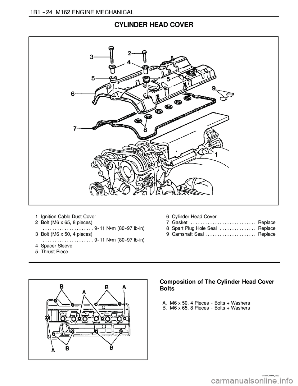
CYLINDER HEAD COVER
1 Ignition Cable Dust Cover
2 Bolt (M6 x 65, 8 pieces)
9--11 NSm (80-- 97 lb-in) .....................
3 Bolt (M6 x 50, 4 pieces)
9--11 NSm (80-- 97 lb-in) .....................
4 Spacer Sleeve
5 Thrust Piece6 Cylinder Head Cover
7 Gasket Replace...........................
8 Spart Plug Hole Seal Replace...............
9 Camshaft Seal Replace.....................
Composition of The Cylinder Head Cover
Bolts
A. M6 x 50, 4 Pieces -- Bolts + Washers
B. M6 x 65, 8 Pieces -- Bolts + Washers
Page 57 of 2053
M162 ENGINE MECHANICAL 1B1 -- 25
D AEW OO M Y_2000
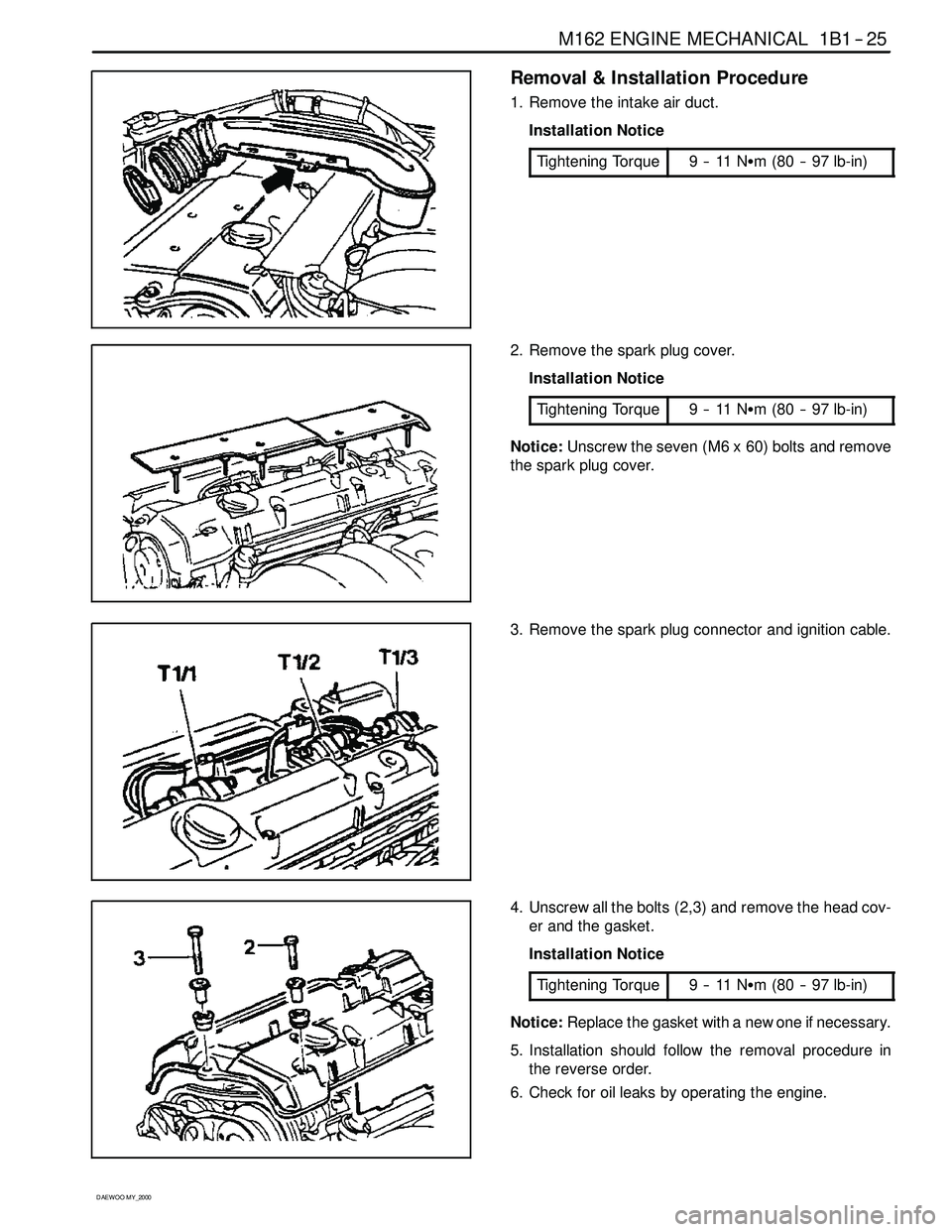
Removal & Installation Procedure
1. Remove the intake air duct.
Installation Notice
Tightening Torque
9--11NSm (80 -- 97 lb-in)
2. Remove the spark plug cover.
Installation Notice
Tightening Torque
9--11NSm (80 -- 97 lb-in)
Notice:Unscrew the seven (M6 x 60) bolts and remove
the spark plug cover.
3. Remove the spark plug connector and ignition cable.
4. Unscrew all the bolts (2,3) and remove the head cov-
er and the gasket.
Installation Notice
Tightening Torque
9--11NSm (80 -- 97 lb-in)
Notice:Replace the gasket with a new one if necessary.
5. Installation should follow the removal procedure in
the reverse order.
6. Check for oil leaks by operating the engine.
Page 58 of 2053
1B1 -- 26 M162 ENGINE MECHANICAL
D AEW OO M Y_2000
CYLINDER HEAD FRONT COVER
Preceding Work: Removal of cylinder head cover
Removal of coolant connection fitting
1 Camshaft Position Sensor
2 Magnet Assembly
3 Upper Guide Rail
4 Bolt (M6 x 60, 3 pieces)
22.5-- 27.5 NSm (16.6-- 20.3 lb-ft) .............5 Bolt (M8 x 80, 3 pieces)
22.5-- 27.5 NSm (16.6--20.3 lb-ft) .............
6 Front Cover
7 Rubber Gasket Replace....................
8 Bolt (M6 x 16, 3 pieces)
9--11 NSm (80-- 97 lb-in) .....................
Page 59 of 2053
M162 ENGINE MECHANICAL 1B1 -- 27
D AEW OO M Y_2000
Removal & Installation Procedure
1. Remove the magnet assembly.
Installation Notice
Tightening Torque
9--11NSm (80 -- 97 lb-in)
2. Remove the cylinder head front cover (6).
Installation Notice
Tightening Torque
22.5 -- 27.5 NSm
(16.6 -- 20.3 lb-ft)
Apply the sealant at the mating surface of the cylinder
head and the front cover.
3. Remove the upper guide rail pin and the guide rail (3).
Installation Notice
Install it while the chain tensioner is loose.
4. Remove the gasket (arrow).
Installation Notice
Replace the gasket with new one and apply the sea-
lant.
5. Installation should follow the removal procedure in
the reverse order.


