engine coolant SSANGYONG KORANDO 1997 Service Service Manual
[x] Cancel search | Manufacturer: SSANGYONG, Model Year: 1997, Model line: KORANDO, Model: SSANGYONG KORANDO 1997Pages: 2053, PDF Size: 88.33 MB
Page 230 of 2053

M162 ENGINE CONTROLS 1F1 -- 67
D AEW OO M Y_2000
3. Turn the ignition switch to “OFF” position.
4. Disconnect the ECT sensor connector.
5. Turn the ignition switch to “ON” position.
6. Measure the resistance between the ECT sensor terminal pin No. 1 and No. 4.
Temperature (°C)
Specified Value (Ω)
202,500
80322
100185
Notice:Replace wiring and coolant temperature sensor if out of specified value.
Page 247 of 2053

1F1 -- 84 M162 ENGINE CONTROLS
D AEW OO M Y_2000
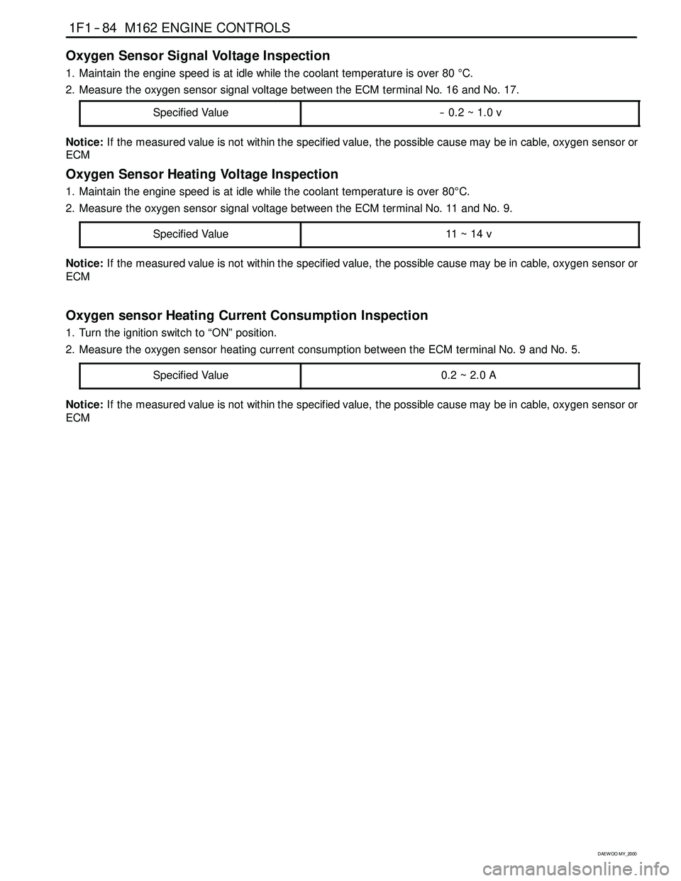
Oxygen Sensor Signal Voltage Inspection
1. Maintain the engine speed is at idle while the coolant temperature is over 80°C.
2. Measure the oxygen sensor signal voltage between the ECM terminal No. 16 and No. 17.
Specified Value
-- 0.2 ~ 1.0 v
Notice:If the measured value is not within the specified value, the possible cause may be in cable, oxygen sensor or
ECM
Oxygen Sensor Heating Voltage Inspection
1. Maintain the engine speed is at idle while the coolant temperature is over 80°C.
2. Measure the oxygen sensor signal voltage between the ECM terminal No. 11 and No. 9.
Specified Value
11 ~ 14 v
Notice:If the measured value is not within the specified value, the possible cause may be in cable, oxygen sensor or
ECM
Oxygen sensor Heating Current Consumption Inspection
1. Turn the ignition switch to “ON” position.
2. Measure the oxygen sensor heating current consumption between the ECM terminal No. 9 and No. 5.
Specified Value
0.2~2.0A
Notice:If the measured value is not within the specified value, the possible cause may be in cable, oxygen sensor or
ECM
Page 263 of 2053

1F1 -- 100 M162 ENGINE CONTROLS
D AEW OO M Y_2000
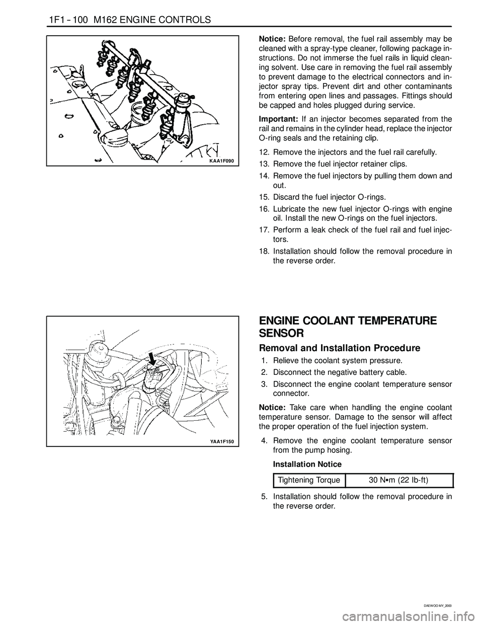
KAA1F090
Notice:Before removal, the fuel rail assembly may be
cleaned with a spray-type cleaner, following package in-
structions. Do not immerse the fuel rails in liquid clean-
ing solvent. Use care in removing the fuel rail assembly
to prevent damage to the electrical connectors and in-
jector spray tips. Prevent dirt and other contaminants
from entering open lines and passages. Fittings should
be capped and holes plugged during service.
Important:If an injector becomes separated from the
rail and remains in the cylinder head, replace the injector
O-ring seals and the retaining clip.
12. Remove the injectors and the fuel rail carefully.
13. Remove the fuel injector retainer clips.
14. Remove the fuel injectors by pulling them down and
out.
15. Discard the fuel injector O-rings.
16. Lubricate the new fuel injector O-rings with engine
oil. Install the new O-rings on the fuel injectors.
17. Perform a leak check of the fuel rail and fuel injec-
tors.
18. Installation should follow the removal procedure in
the reverse order.
YAA1F150
ENGINE COOLANT TEMPERATURE
SENSOR
Removal and Installation Procedure
1. Relieve the coolant system pressure.
2. Disconnect the negative battery cable.
3. Disconnect the engine coolant temperature sensor
connector.
Notice:Take care when handling the engine coolant
temperature sensor. Damage to the sensor will affect
the proper operation of the fuel injection system.
4. Remove the engine coolant temperature sensor
from the pump hosing.
Installation Notice
Tightening Torque
30 NSm (22 Ib-ft)
5. Installation should follow the removal procedure in
the reverse order.
Page 284 of 2053

1A2 -- 12 GENERAL ENGINE INFORMATION
D AEW OO M Y_2000
Leakage Test
1. Warm the engine up to normal operating tempera-
ture.
2. Disconnect the negative battery cable.
3. Remove the spark plugs.
4. Check the coolant level by opening the coolant
surge tank cap and replenish if insufficient.
5. Open the engine oil filler cap.
6. Connect the tester to air pressure line and adjust the
scale of tester.
7. Install the connecting hose to spark plug hole.
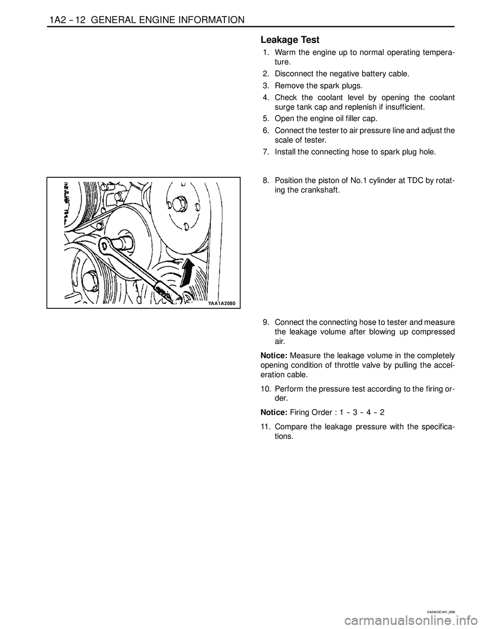
YAA1A2080
8. Position the piston of No.1 cylinder at TDC by rotat-
ing the crankshaft.
9. Connect the connecting hose to tester and measure
the leakage volume after blowing up compressed
air.
Notice:Measure the leakage volume in the completely
opening condition of throttle valve by pulling the accel-
eration cable.
10. Perform the pressure test according to the firing or-
der.
Notice:Firing Order : 1 -- 3 -- 4 -- 2
11. Compare the leakage pressure with the specifica-
tions.
Page 301 of 2053

1B2 -- 8 M161 ENGINE MECHANICAL
D AEW OO M Y_2000
Removal & Installation Procedure
1. Disconnect the negative terminal of battery.
2. Remove the hood.
3. Remove the under cover.
Installation Notice
Tightening Torque
28 -- 47 NSm (21 -- 35 lb-ft)
4. Disconnect the coupling of HFM sensor and remove
the air cleaner cross pipe.
5. Remove the air cleaner cover. Remove the mounting
bolts and air cleaner housing and element assembly.
6. Loosen the radiator drain cock and drain the coolant.
Notice:Open the coolant reservoir cap.
Page 302 of 2053

M161 ENGINE MECHANICAL 1B2 -- 9
D AEW OO M Y_2000
7. Loosen the cylinder block drain plug and then drain
the coolant completely.
Installation Notice
Tightening Torque
30 NSm (22 lb-ft)
Notice:Replace the seal before installation of the drain
plug.
8. Remove the cooling fan shroud. Refer toSection
1D2, Engine Cooling.
9. Disconnect the each hose from radiator.
10. Remove the upper mounting bolts of radiator and
then remove the radiator.
Page 304 of 2053

M161 ENGINE MECHANICAL 1B2 -- 11
D AEW OO M Y_2000
15. Disconnect the terminals from starter motor and re-
move the starter motor.
16. Disconnect the engine main harness ground.
17. Disconnect the engine ground wire.
18. Disconnect following sensors connector.
DHFM sensor.
DCoolant temperature sensor.
DKnock sensor.
DCamshaft and crankshaft sensors.
19. After removing the ignition coil cover, disconnect the
ignition coil connector.
20. Remove the harness cover and disconnect the 4 in-
jection valve connectors. Disconnect the main har-
ness.
Page 388 of 2053

1B2 -- 100 M161 ENGINE MECHANICAL
D AEW OO M Y_2000
UNIT REPAIR
CORE PLUGS IN CRANKCASE
Preceding Work: Draining of the coolant
1 Core Plug Replace.........................
Page 389 of 2053

M161 ENGINE MECHANICAL 1B2 -- 101
D AEW OO M Y_2000
Tools Required
102589001500 Drift
Replacement Procedure
1. Remove the intake and exhaust manifolds.
2. Pull back the core plug until the end of one side
comes out using the screw driver.
3. Pull out the plug carefully using a pliers.
4. Clean the sealing surface and apply Loctite 241.
5. Press in new plug using a drift.
Notice:Wait for about 45minutes before filling the cool-
ant so that the Loctite 241 hardens.
6. Warm up the engine and check the coolant for leaks.
Page 396 of 2053

D AEW OO M Y_2000
SECTION 1D2
M161 ENGINE COOLING
CAUTION: Disconnect the negative battery cable before removing or installing any electrical unit or when a
tool or equipment could easily come in contact with exposed electrical terminals. Disconnecting this cable
will help prevent personal injury and damage to the vehicle. The ignition must also be in LOCK unless other -
wise noted.
TABLE OF CONTENTS
Specifications 1D2 -- 2............................
General Specifications 1D2-- 2....................
Fastener Tightening Specifications 1D2 -- 2..........
Special Tools 1D2 -- 3.............................
Special Tools Table 1D2-- 3.......................
Diagnosis 1D2 -- 4.................................
System Leakage Test 1D2-- 4.....................
Maintenance and Repair 1D2 -- 5...................
On-- Vehicle Service 1D2-- 5.........................Coolant Drain and Fill Up 1D2 -- 5..................
Cooling Fan and Viscous Clutch 1D2 -- 7............
Wat er Pum p 1D2 -- 9.............................
Thermostat 1D2 -- 11.............................
Thermostat Housing Assembly 1D2 -- 12............
Removal and Installation of Cooling
Fan Shroud 1D2 -- 14...........................
Removal and Installation of Radiator 1D2-- 15.......