warning SSANGYONG KORANDO 1997 Service Repair Manual
[x] Cancel search | Manufacturer: SSANGYONG, Model Year: 1997, Model line: KORANDO, Model: SSANGYONG KORANDO 1997Pages: 2053, PDF Size: 88.33 MB
Page 13 of 2053

GENERAL INFORMATION 0B -- 13
D AEW OO M Y_2000
OWNER INSPECTIONS AND SERVICES
WHILE OPERATING THE VEHICLE
Horn Operation
Blow the horn occasionally to make sure it works. Check
all the button locations.
Brake System Operation
Be alert for abnormal sounds, increased brake pedal
travel or repeated puling to one side when braking. Also,
if the brake warning light goes on, or flashes, something
may be wrong with part of the brake system.
Exhaust System Operation
Be alert to any changes inthe sound of the system or
the smell of the fumes. These are signs that the system
may be leaking or overheating. Have the system in-
spected and repaired immediately.
Tires, Wheels and Alignment Operation
Be alert to any vibration of the steering wheel or the
seats at normal highway speeds. This may mean a
wheel needs to be balanced. Also, a pull right or left on a
straight, level road may show the need for a tire pres-
sure adjustment or a wheel alignment.
Steering System Operation
Be alert to changes in the steering action. An inspection
is needed when the steering wheel is hard to turn or has
too much free play, or is unusual sounds are noticed
when turning or parking.
Headlight Aim
Take note of the light pattern occasionally. Adjust the
headlights if the beams seem improperly aimed.
AT EACH FUEL FILL
A fluid loss in any (except windshield washer) system
may indicate a problem. Have the system inspected and
repaired immediately.
Engine Oil Level
Check the oil level and add oil if necessary. The best
time to check the engine oil level is when the oil is warm.
1. After stopping the engine, wait a few minutes for the
oil to drain back to the oil pan.
2. Pull out the oil level indicator (dip stick).
3. Wipe it clean, and push the oil level indicator back
down all the way.
4. Pull out the oil level indicator and look at the oil level
on it.
5. Add oil, if needed, to keep the oil level above the low-
er mark. Avoid overfilling theengine, since this may
cause engine damage.
6. Push the indicator all the way back down into the en-
gine after taking the reading.If you check the oil level when the oil is cold, do not run
the engine first. The cold oil will not drain back to the pan
fast enough to give a true oil level reading.
Engine Coolant Level and Condition
Check the coolant level in the coolant reservoir tank and
add coolant if necessary. Inspect the coolant. Replace
dirty or rusty coolant.
Windshield Washer Fluid Level
Check the washer fluid level in the reservoir. Add fluid if
necessary.
AT LEAST TWICE A MONTH
Tire And Wheel Inspection and Pressure
Check
Check the tire for abnormal wear or damage. Also check
for damaged wheels. Check the tire pressure when the
tires are cold ( check the spare also, unless it is a stow-
away). Maintain the recommended pressures. Refer to
“Tire and Wheel” is in section 0B.
AT LEAST MONTHLY
Light Operation
Check the operation of the license plate light, the head-
lights (including the high beams), the parking lights, the
fog lights, the taillight, the brake lights, the turn signals,
the backup lights and the hazard warning flasher.
Fluid Leak Check
Periodically inspect the surface beneath the vehicle for
water, oil, fuel or other fluids, after the vehicle has been
parked for a while. Water dripping from the air condition-
ing system after use is normal. If you notice fuel leaks or
fumes, find the cause and correct it at once.
AT LEAST TWICE A YEAR
Power Steering System Reservoir Level
Check the power steering fluid level. Keep the power
steering fluid at the proper level. Refer to Section 6A,
Power Steering System.
Brake Master Cylinder Reservoir Level
Check the fluid and keep it at the proper level. A low fluid
level can indicate worn disc brake pads which may need
to be serviced. Check the breather hole in the reservoir
cover to be free from dirt and check for an open pas-
sage.
Weather- Strip Lubrication
Apply a thin film silicone grease using a clean cloth.
Page 238 of 2053

M162 ENGINE CONTROLS 1F1 -- 75
D AEW OO M Y_2000
TRACTION CONTROLSYSTEM (TCS)
KAB1F310
Failure
CodeDescriptionTrouble AreaMaintenance Hint
150TCS input signal short
circuit to batteryTCS short circuit to powerDInspection the Engine Control Module
(ECM) pin 45 about short circuit or
openwithbadcontact
151TCS input signal short
circuit to ground or openTCS short circuit to ground or
open
openwithbadcontact
DInspection the TCS lamp of I/P cluster.
DInspection the ECM
Circuit Description
Battery voltage is supplied to the TCS warning lamp with the ignition in ON and START. The warning lamp can be
activated only by the Electrical Brake Control Module (EBCM) internally supplying ground to terminal 32. If the TCS
input circuit is open or short, this failure codewill be set.
Page 493 of 2053

M161 ENGINE CONTROLS 1F2 -- 75
D AEW OO M Y_2000
TRACTION CONTROLSYSTEM (TCS)
KAB1F310
Failure
CodeDescriptionTrouble AreaMaintenance Hint
150TCS input signal short
circuit to batteryTCS short circuit to powerDInspection the Engine Control Module
(ECM) pin 45 about short circuit or
openwithbadcontact
151TCS input signal short
circuit to ground or openTCS short circuit to ground or
open
openwithbadcontact
DInspection the TCS lamp of I/P cluster.
DInspection the ECM
Circuit Description
Battery voltage is supplied to the TCS warning lamp with the ignition in ON and START. The warning lamp can be
activated only by the Electrical Brake Control Module (EBCM) internally supplying ground to terminal 32. If the TCS
input circuit is open or short, this failure codewill be set.
Page 921 of 2053

SECTION 4A
HYDRAULIC BRAKES
CAUTION: Disconnect the negative battery cable before removing or installing any electrical unit or when
a tool or equipment could easily come in contact with exposed electrical terminals. Disconnecting this
cable will help prevent personal injury and damage to the vehicle. The ignition must also be in LOCK
unless otherwise noted.
TABLE OF CONTENTS
Description and Operation...................................4A-2
General Description.............................................4A-2
Diagnostic Information and Procedures..............4A-3
Brake System Testing ..........................................4A-3
Brake Hose Inspection.........................................4A-3
Brake Warning Lamp Circuit Description..............4A-4
Brake Warning Lamp Diagnosis...........................4A-5
LCRV (Load Conscious Reducing Valve)..............4A-8
Repair Instructions..............................................4A-10On-Vehicle Service...............................................4A-10
Manual Bleeding The Brakes.............................4A-10
Front Brake Hose...............................................4A-13
Rear Brake Hose...............................................4A-13
Stoplamp Switch................................................4A-14
Brake Pedal.......................................................4A-14
Specifications.....................................................4A-15
General Specification .........................................4A-15
Fastener Tightening Specifications.....................4A-16
Page 924 of 2053

SSAMGYONG MY2002
4A-4 HYDRAULIC BRAKES
KAA4A010
BRAKE WARNING LAMP CIRCUIT DESCRIPTION
Diagnostic Aids
The BRAKE lamp glows brightly when the ignition is
ON and either the parking brake lever switch or the
brake fluid level switch is closed.
If neither switch is closed, the BRAKE lamp receives
a ground through the generator, and it glows dimly
when the ignition is ON and the engine is off. When
the engine starts, the generator creates voltage. With
voltage on both sides of the lamp, the lamp turns off.
Test Description
The numbers below refer to steps in the diagnostic
table.
1. This step begins the test sequence for a BRAKE
warning lamp that stays on when the engine is run-
ning.
2. This step begins the test sequence for a BRAKE
warning lamp that never turns on.
Page 925 of 2053

HYDRAULIC BRAKES 4A-5
SSANGYONG MY2002
Value(s)
-
-
-
-
-
-
-
-
-
-
-
-
-
-
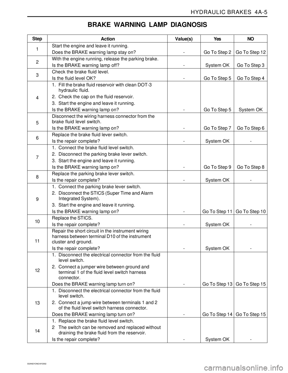
BRAKE WARNING LAMP DIAGNOSIS
Step
1
2
3
4
5
6
7
8
9
10
11
12
13
14Action
Start the engine and leave it running.
Does the BRAKE warning lamp stay on?
With the engine running, release the parking brake.
Is the BRAKE warning lamp off?
Check the brake fluid level.
Is the fluid level OK?
1. Fill the brake fluid reservoir with clean DOT-3
hydraulic fluid.
2. Check the cap on the fluid reservoir.
3. Start the engine and leave it running.
Is the BRAKE warning lamp on?
Disconnect the wiring harness connector from the
brake fluid level switch.
Is the BRAKE warning lamp on?
Replace the brake fluid lever switch.
Is the repair complete?
1. Connect the brake fluid level switch.
2. Disconnect the parking brake lever switch.
3. Start the engine and leave it running.
Is the BRAKE warning lamp on?
Replace the parking brake lever switch.
Is the repair complete?
1. Connect the parking brake lever switch.
2. Disconnect the STICS (Super Time and Alarm
Integrated System).
3. Start the engine and leave it running.
Is the BRAKE warning lamp on?
Replace the STICS.
Is the repair complete?
Repair the short circuit in the instrument wiring
harness between terminal D10 of the instrument
cluster and ground.
Is the repair complete?
1. Disconnect the electrical connector from the fluid
level switch.
2. Connect a jumper wire between ground and
terminal 1 of the fluid level switch harness
connector.
Does the BRAKE warning lamp turn on?
1. Disconnect the electrical connector from the fluid
level switch.
2. Connect a jump wire between terminals 1 and 2
of the fluid level switch harness connector.
Does the BRAKE warning lamp turn on?
1. Replace the brake fluid level switch.
2 The switch can be removed and replaced without
draining the brake fluid from the reservoir.
Is the repair complete?Yes
Go To Step 2
System OK
Go To Step 5
Go To Step 5
Go To Step 7
System OK
Go To Step 9
System OK
Go To Step 11
System OK
System OK
Go To Step 13
Go To Step 14
System OKNO
Go To Step 12
Go To Step 3
Go To Step 4
System OK
Go To Step 6
-
Go To Step 8
-
Go To Step 10
-
-
Go To Step 15
Go To Step 15
-
Page 926 of 2053

SSAMGYONG MY2002
4A-6 HYDRAULIC BRAKES
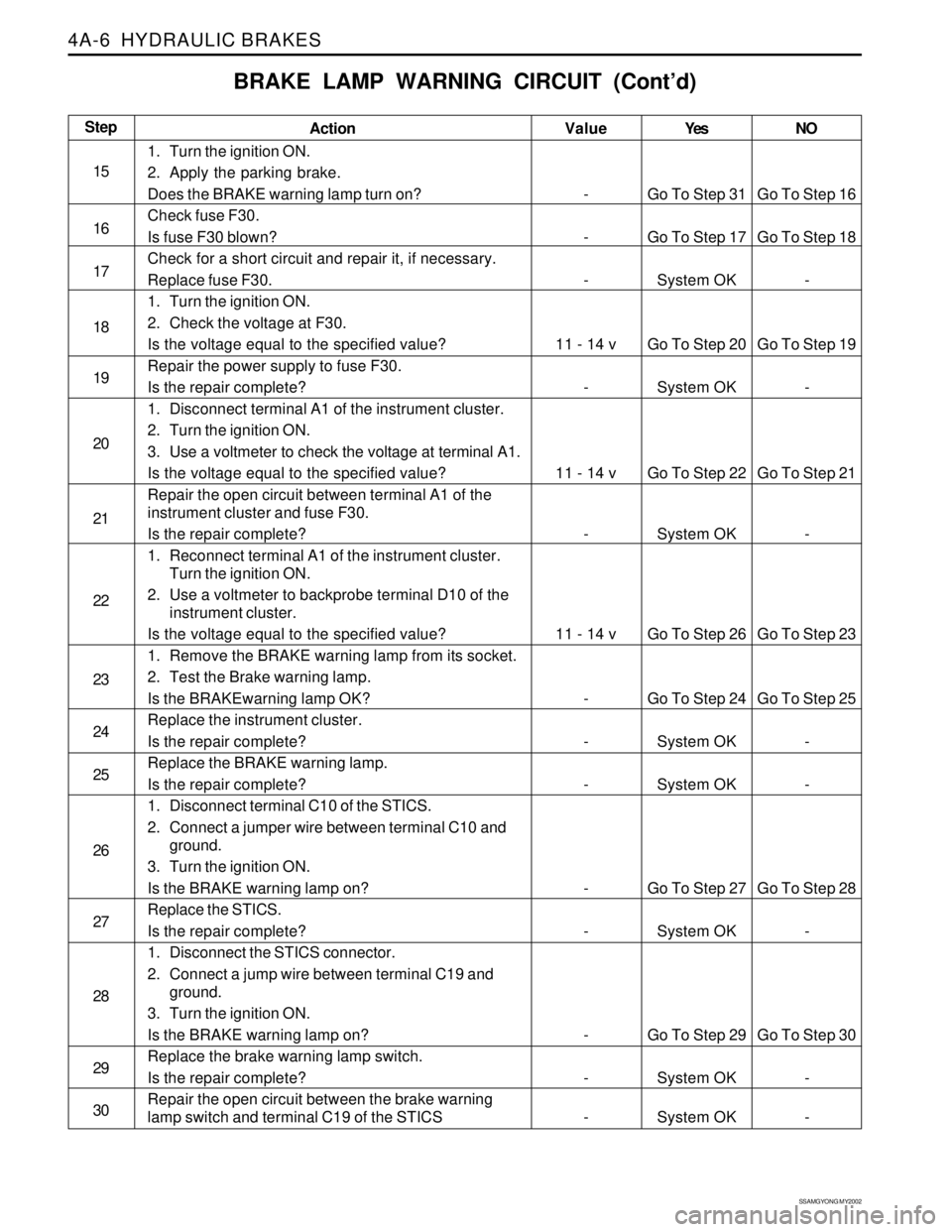
Action
1. Turn the ignition ON.
2. Apply the parking brake.
Does the BRAKE warning lamp turn on?
Check fuse F30.
Is fuse F30 blown?
Check for a short circuit and repair it, if necessary.
Replace fuse F30.
1. Turn the ignition ON.
2. Check the voltage at F30.
Is the voltage equal to the specified value?
Repair the power supply to fuse F30.
Is the repair complete?
1. Disconnect terminal A1 of the instrument cluster.
2. Turn the ignition ON.
3. Use a voltmeter to check the voltage at terminal A1.
Is the voltage equal to the specified value?
Repair the open circuit between terminal A1 of the
instrument cluster and fuse F30.
Is the repair complete?
1. Reconnect terminal A1 of the instrument cluster.
Turn the ignition ON.
2. Use a voltmeter to backprobe terminal D10 of the
instrument cluster.
Is the voltage equal to the specified value?
1. Remove the BRAKE warning lamp from its socket.
2. Test the Brake warning lamp.
Is the BRAKEwarning lamp OK?
Replace the instrument cluster.
Is the repair complete?
Replace the BRAKE warning lamp.
Is the repair complete?
1. Disconnect terminal C10 of the STICS.
2. Connect a jumper wire between terminal C10 and
ground.
3. Turn the ignition ON.
Is the BRAKE warning lamp on?
Replace the STICS.
Is the repair complete?
1. Disconnect the STICS connector.
2. Connect a jump wire between terminal C19 and
ground.
3. Turn the ignition ON.
Is the BRAKE warning lamp on?
Replace the brake warning lamp switch.
Is the repair complete?
Repair the open circuit between the brake warning
lamp switch and terminal C19 of the STICS
BRAKE LAMP WARNING CIRCUIT (Cont’d)
Yes
Go To Step 31
Go To Step 17
System OK
Go To Step 20
System OK
Go To Step 22
System OK
Go To Step 26
Go To Step 24
System OK
System OK
Go To Step 27
System OK
Go To Step 29
System OK
System OKNO
Go To Step 16
Go To Step 18
-
Go To Step 19
-
Go To Step 21
-
Go To Step 23
Go To Step 25
-
-
Go To Step 28
-
Go To Step 30
-
-Step
15
16
17
18
19
20
21
22
23
24
25
26
27
28
29
30Value
-
-
-
11 - 14 v
-
11 - 14 v
-
11 - 14 v
-
-
-
-
-
-
-
-
Page 927 of 2053

HYDRAULIC BRAKES 4A-7
SSANGYONG MY2002
BRAKE LAMP WARNING CIRCUIT (Cont’d)
Action
1. Disconnect the brake fluid level switch.
2. Use an ohmmeter to check the resistance between
terminal 2 of the switch connector and ground.
Is the resistance equal to the specified value?
Repair the open circuit between ground and the brake
fluid level switch.
Is the repair complete?
Repair the open circuit between terminal 1 of the brake
fluid level switch and terminal D10 of the instrument
cluster.
Is the repair complete?Yes
Go To Step 32
System OK
System OKNO
Go To Step 33
-
-Step
31
32
33Value(s)
≈ 0 Ω
-
-
Page 988 of 2053

SSANGYONG MY2002
4F-4 ABS AND TCS
Pressure Modulation
Depending on the control deviation and the wheel accel-
eration of the spinning wheel, pressure increase, hold
and decrease are made.
The pressure modulation is done with the conventional
control with the valves. Prime valve, pilot valve, inlet
valve and outlet valve according to the following table:
Speed Range
TCS is available in the speed range ≤ 60 kph.
Above 60 kph vehicle speed, TCS is passive.
It is possible to initiate TCS operation up to a vehicle
speed of 55 kph.
Prime Valve
Pilot Valve
Inlet Valve
Outlet Valve
Increase
Open
Closed
Open
ClosedHold
Open
Closed
Closed
ClosedDecrease
Open
Closed
Closed
Open
System Failure (EBD,
ABS or TCS are Not
Distinguished)
ABS Warning
LampIgnition ONABS
OperationTCS
OperationTCS Passive Due to
Temperature Model
2 second on
for lamp
checkOFF OFF ON OFF
TCS Info
Lamp2 second on
for lamp
checkOFFBlinking
(FLASHING)OFF ON
EBD Warning
Lamp2 second on
for lamp
checkEBD
operation/OFFOFF ON OFF
Temperature Model
TCS operation is a high thermal load for the brakes.
To avoid any damages at the brakes, the disk tempera-
ture is calculated with a mathematical model for each
driven wheel separately. After ignition on, the
calculation starts with 30°C and then three different
phases are evaluated separately and added:
TCS operation, braking and coling phase.
If the temperature is highter than 500°C, TCS is dis-
abled for this wheel.
It is permitted again, if the model has calculated down
the 350°C.
Lamp Concepts
The system is equipped with an TCS information lamp,
which is blinking during TCS operation.
The activation of the EBD, TCS warning lamp and the
TCS info lamp issummarized in thefollowing table:
Page 997 of 2053

SSANGYONG MY2002
4F-14 ABS AND TCS
COMPONENT LOCATOR
ABS, ABS/TCS 5.3
1 ABS/TCS Hydraulic Unit
(with EBCM in case of ABS only)
2 ABS/TCS EBCM Unit (in case of TCS)
3 Rear Wheel Speed Sensor
KAA4F100
4 ABS Warning Indicator Light
5 Diagnosis Connector
6 Front Wheel Speed Sensor
7 Acceleration Sensor