engine coolant SSANGYONG KORANDO 1997 Service Manual PDF
[x] Cancel search | Manufacturer: SSANGYONG, Model Year: 1997, Model line: KORANDO, Model: SSANGYONG KORANDO 1997Pages: 2053, PDF Size: 88.33 MB
Page 482 of 2053
1F2 -- 64 M161 ENGINE CONTROLS
D AEW OO M Y_2000
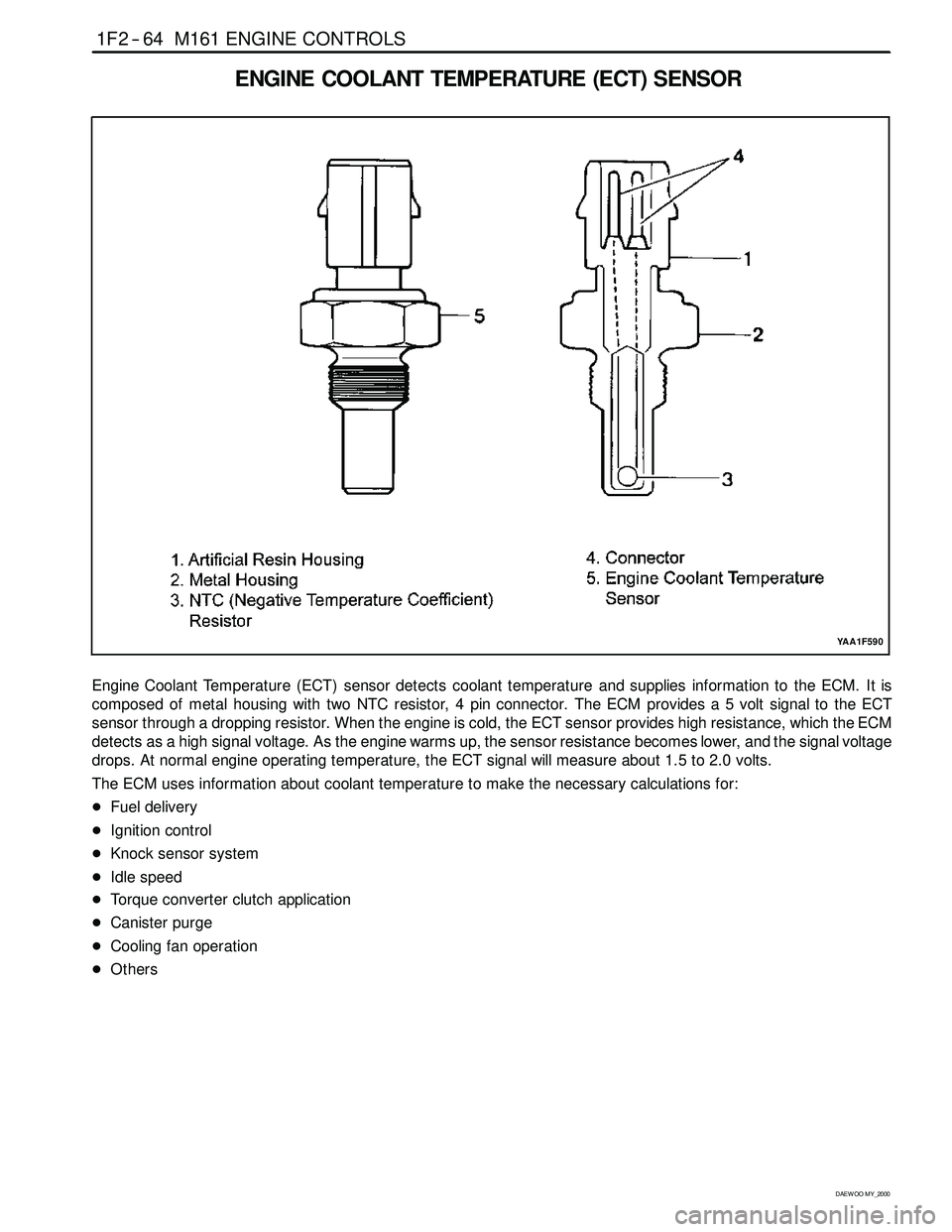
ENGINE COOLANT TEMPERATURE (ECT) SENSOR
YAA1F590
Engine Coolant Temperature (ECT) sensor detects coolant temperature and supplies information to the ECM. It is
composed of metal housing with two NTC resistor, 4 pin connector. The ECM provides a 5 volt signal to the ECT
sensor through a dropping resistor. When the engine is cold, the ECT sensor provides high resistance, which the ECM
detects as a high signal voltage. As the engine warms up, the sensor resistance becomes lower, and the signal voltage
drops. At normal engine operating temperature, the ECT signalwill measure about 1.5 to 2.0 volts.
The ECM uses information about coolant temperature to make the necessary calculations for:
DFuel delivery
DIgnition control
DKnock sensor system
DIdle speed
DTorque converter clutch application
DCanister purge
DCooling fan operation
DOthers
Page 484 of 2053
1F2 -- 66 M161 ENGINE CONTROLS
D AEW OO M Y_2000
KAB1F260
Failure
CodeDescriptionTrouble AreaMaintenance Hint
00
Engine coolant
temperature sensor low
voltageECT sensor short circuit to
ground or open
01
Engine coolant
temperature sensor high
voltageECT sensor short circuit to
power
DMonitoring the actual coolant
temperaturethroughscantool
02
Engine coolant
temperature sensor
plausibilityMalfunction in recognition of
ECT
When drop to about 50°C
below after warm uptemperaturethroughscantool
DInspection the ECM pin 78, 79 about
short circuit or open with bad contact
DInspection the ECT sensor
DIns
pection the ECM
06
Engine coolant
temperature insufficient
for closed loop fuel
controlMalfunction in recognition of
ECT
When minimum temperature
for lambda control after warm
up
DInspectiontheECM
Circuit Description
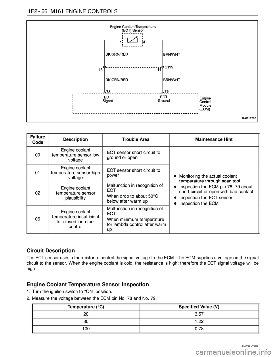
The ECT sensor uses a thermistor to control the signal voltage to the ECM. The ECM supplies a voltage on the signal
circuit to the sensor. When the engine coolant is cold, the resistance is high; therefore the ECT signal voltagewill be
high
Engine Coolant Temperature Sensor Inspection
1. Turn the ignition switch to “ON” position.
2. Measure the voltage between the ECM pin No. 78 and No. 79.
Temperature (°C)
Specified Value (V)
203.57
801.22
1000.78
Page 485 of 2053
M161 ENGINE CONTROLS 1F2 -- 67
D AEW OO M Y_2000
3. Turn the ignition switch to “OFF” position.
4. Disconnect the ECT sensor connector.
5. Turn the ignition switch to “ON” position.
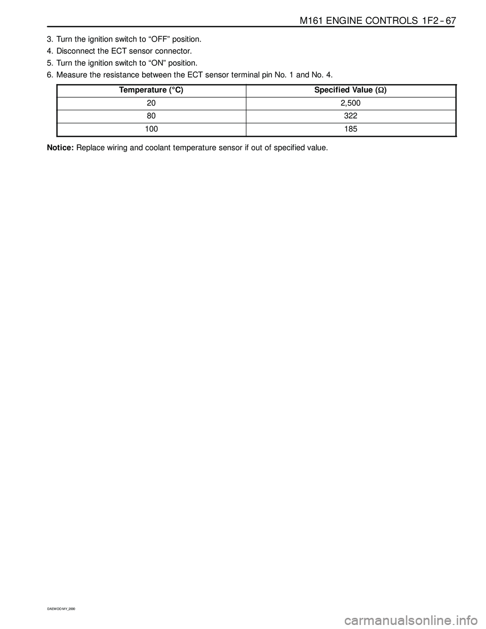
6. Measure the resistance between the ECT sensor terminal pin No. 1 and No. 4.
Temperature (°C)
Specified Value (Ω)
202,500
80322
100185
Notice:Replace wiring and coolant temperature sensor if out of specified value.
Page 502 of 2053
1F2 -- 84 M161 ENGINE CONTROLS
D AEW OO M Y_2000
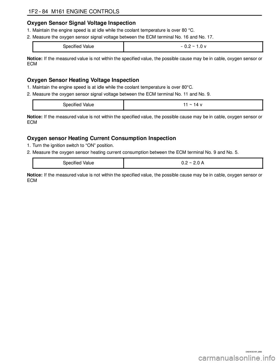
Oxygen Sensor Signal Voltage Inspection
1. Maintain the engine speed is at idle while the coolant temperature is over 80°C.
2. Measure the oxygen sensor signal voltage between the ECM terminal No. 16 and No. 17.
Specified Value
-- 0.2 ~ 1.0 v
Notice:If the measured value is not within the specified value, the possible cause may be in cable, oxygen sensor or
ECM
Oxygen Sensor Heating Voltage Inspection
1. Maintain the engine speed is at idle while the coolant temperature is over 80°C.
2. Measure the oxygen sensor signal voltage between the ECM terminal No. 11 and No. 9.
Specified Value
11 ~ 14 v
Notice:If the measured value is not within the specified value, the possible cause may be in cable, oxygen sensor or
ECM
Oxygen sensor Heating Current Consumption Inspection
1. Turn the ignition switch to “ON” position.
2. Measure the oxygen sensor heating current consumption between the ECM terminal No. 9 and No. 5.
Specified Value
0.2~2.0A
Notice:If the measured value is not within the specified value, the possible cause may be in cable, oxygen sensor or
ECM
Page 518 of 2053
1F2 -- 100 M161 ENGINE CONTROLS
D AEW OO M Y_2000
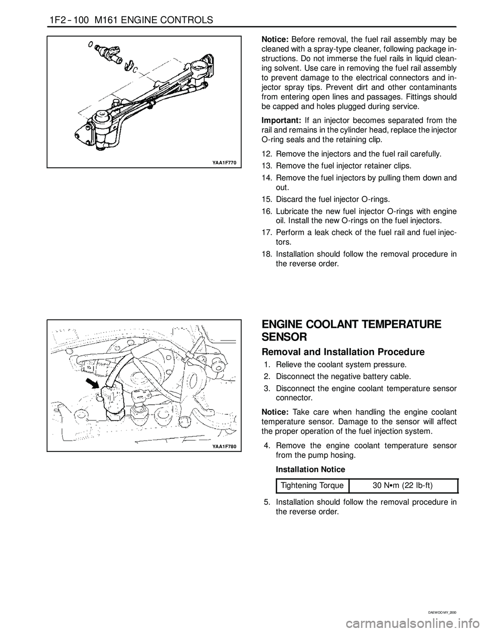
YAA1F770
Notice:Before removal, the fuel rail assembly may be
cleaned with a spray-type cleaner, following package in-
structions. Do not immerse the fuel rails in liquid clean-
ing solvent. Use care in removing the fuel rail assembly
to prevent damage to the electrical connectors and in-
jector spray tips. Prevent dirt and other contaminants
from entering open lines and passages. Fittings should
be capped and holes plugged during service.
Important:If an injector becomes separated from the
rail and remains in the cylinder head, replace the injector
O-ring seals and the retaining clip.
12. Remove the injectors and the fuel rail carefully.
13. Remove the fuel injector retainer clips.
14. Remove the fuel injectors by pulling them down and
out.
15. Discard the fuel injector O-rings.
16. Lubricate the new fuel injector O-rings with engine
oil. Install the new O-rings on the fuel injectors.
17. Perform a leak check of the fuel rail and fuel injec-
tors.
18. Installation should follow the removal procedure in
the reverse order.
YAA1F780
ENGINE COOLANT TEMPERATURE
SENSOR
Removal and Installation Procedure
1. Relieve the coolant system pressure.
2. Disconnect the negative battery cable.
3. Disconnect the engine coolant temperature sensor
connector.
Notice:Take care when handling the engine coolant
temperature sensor. Damage to the sensor will affect
the proper operation of the fuel injection system.
4. Remove the engine coolant temperature sensor
from the pump hosing.
Installation Notice
Tightening Torque
30 NSm (22 Ib-ft)
5. Installation should follow the removal procedure in
the reverse order.
Page 547 of 2053
1A3 -- 12 GENERAL ENGINE INFORMATION
D AEW OO M Y_2000
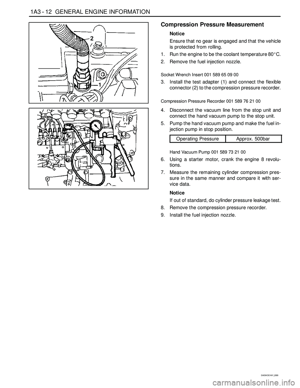
Compression Pressure Measurement
Notice
Ensure that no gear is engaged and that the vehicle
is protected from rolling.
1. Run the engine to be the coolant temperature 80_C.
2. Remove the fuel injection nozzle.
Socket Wrench Insert 001 589 65 09 00
3. Install the test adapter (1) and connect the flexible
connector (2) to the compression pressure recorder.
Compression Pressure Recorder 001 589 76 21 00
4. Disconnect the vacuum line from the stop unit and
connect the hand vacuum pump to the stop unit.
5. Pump the hand vacuum pump and make the fuel in-
jection pump in stop position.
Operating PressureApprox. 500bar
Hand Vacuum Pump 001 589 73 21 00
6. Using a starter motor, crank the engine 8 revolu-
tions.
7. Measure the remaining cylinder compression pres-
sure in the same manner and compare it with ser-
vice data.
Notice
If out of standard, do cylinder pressure leakage test.
8. Remove the compression pressure recorder.
9. Install the fuel injection nozzle.
Page 549 of 2053
1A3 -- 14 GENERAL ENGINE INFORMATION
D AEW OO M Y_2000
Leakage Test
1. Run the engine to be the coolant temperature 80_C.
2. Remove the fuel injection nozzle.
3. Open the coolant subtank cap.
4. Check the coolant level and replenish if necessary.
5. Open the oil filler cap.
6. Remove the air cleaner cover and element.
7. Position the piston at TDC.
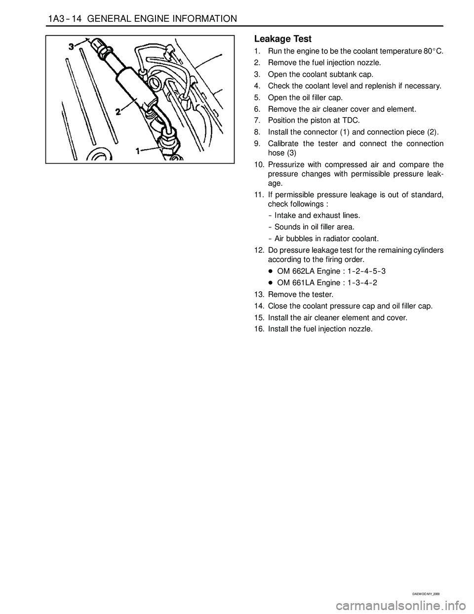
8. Install the connector (1) and connection piece (2).
9. Calibrate the tester and connect the connection
hose (3)
10. Pressurize with compressed air and compare the
pressure changes with permissible pressure leak-
age.
11. If permissible pressure leakage is out of standard,
check followings :
-- Intake and exhaust lines.
-- Sounds in oil filler area.
-- Air bubbles in radiator coolant.
12. Do pressure leakage test for the remaining cylinders
according to the firing order.
DOM 662LA Engine : 1-- 2-- 4-- 5-- 3
DOM 661LA Engine : 1-- 3-- 4-- 2
13. Remove the tester.
14. Close the coolant pressure cap and oil filler cap.
15. Install the air cleaner element and cover.
16. Install the fuel injection nozzle.
Page 562 of 2053
OM600 ENGINE MECHANICAL 1B3 -- 13
D AEW OO M Y_2000
Removal & Installation Procedure
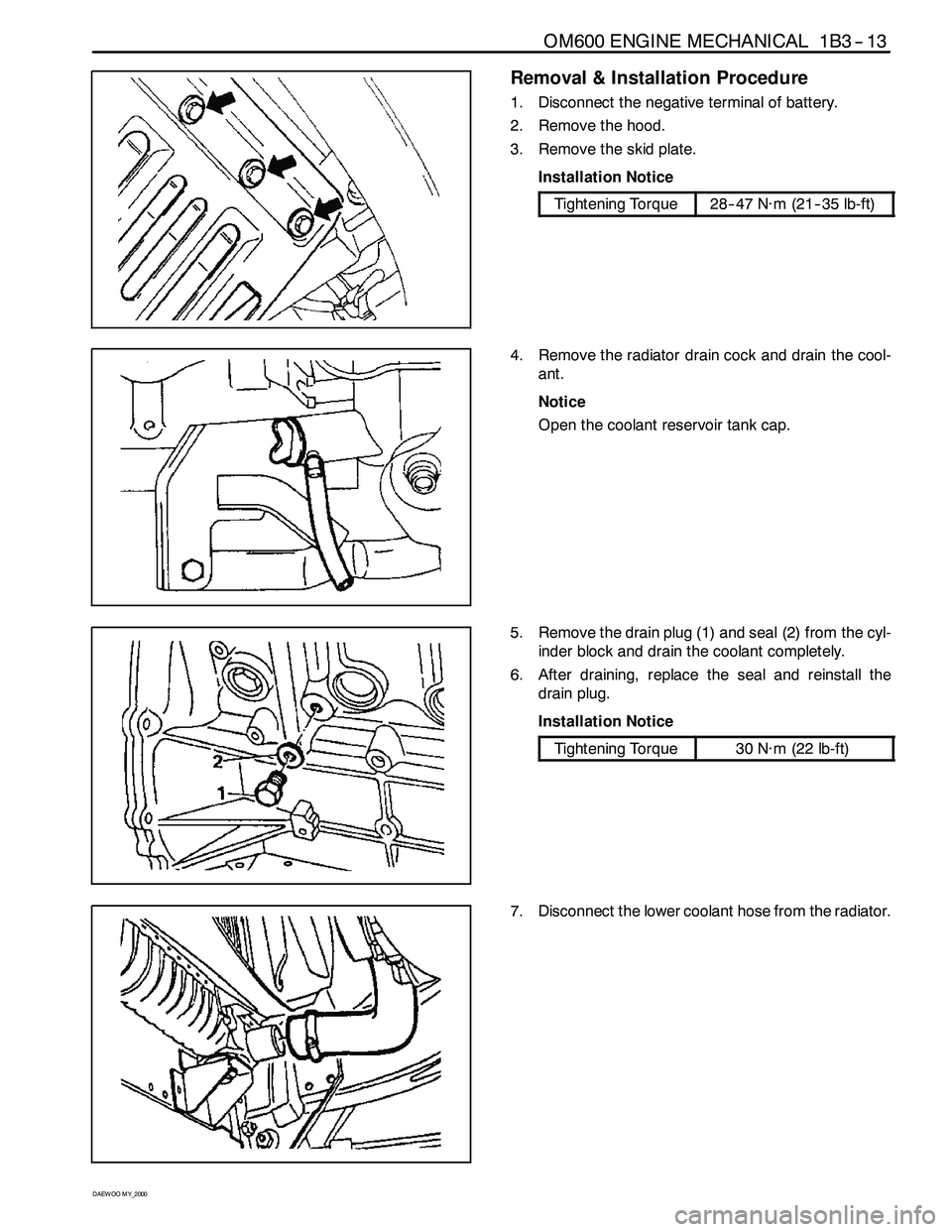
1. Disconnect the negative terminal of battery.
2. Remove the hood.
3. Remove the skid plate.
Installation Notice
Tightening Torque28-- 47 N∙m (21-- 35 lb-ft)
4. Remove the radiator drain cock and drain the cool-
ant.
Notice
Open the coolant reservoir tank cap.
5. Remove the drain plug (1) and seal (2) from the cyl-
inder block and drain the coolant completely.
6. After draining, replace the seal and reinstall the
drain plug.
Installation Notice
Tightening Torque30 N∙m (22 lb-ft)
7. Disconnect the lower coolant hose from the radiator.
Page 563 of 2053
1B3 -- 14 OM600 ENGINE MECHANICAL
D AEW OO M Y_2000
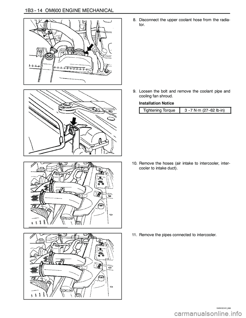
8. Disconnect the upper coolant hose from the radia-
tor.
9. Loosen the bolt and remove the coolant pipe and
cooling fan shroud.
Installation Notice
Tightening Torque3--7N∙m (27-- 62 lb-in)
10. Remove the hoses (air intake to intercooler, inter-
cooler to intake duct).
11. Remove the pipes connected to intercooler.
Page 564 of 2053
OM600 ENGINE MECHANICAL 1B3 -- 15
D AEW OO M Y_2000
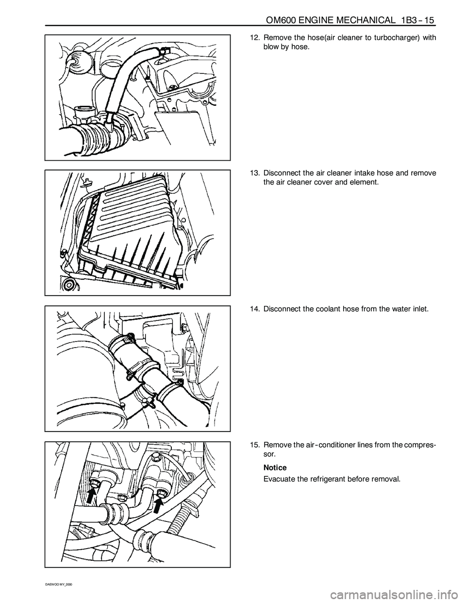
12. Remove the hose(air cleaner to turbocharger) with
blow by hose.
13. Disconnect the air cleaner intake hose and remove
the air cleaner cover and element.
14. Disconnect the coolant hose from the water inlet.
15. Remove the air -- conditioner lines from the compres-
sor.
Notice
Evacuate the refrigerant before removal.