sensor SSANGYONG KORANDO 1997 Service Manual PDF
[x] Cancel search | Manufacturer: SSANGYONG, Model Year: 1997, Model line: KORANDO, Model: SSANGYONG KORANDO 1997Pages: 2053, PDF Size: 88.33 MB
Page 442 of 2053
1F2 -- 22 M161 ENGINE CONTROLS
D AEW OO M Y_2000
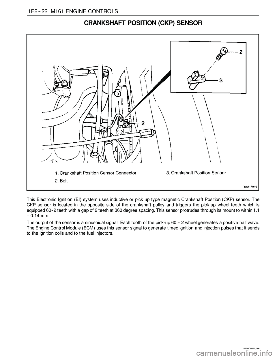
CRANKSHAFT POSITION (CKP) SENSOR
YAA1F940
This Electronic Ignition (EI) system uses inductive or pickup type magnetic Crankshaft Position (CKP) sensor. The
CKP sensor is located in the opposite side of the crankshaft pulley and triggers the pick-up wheel teeth which is
equipped 60 -- 2 teeth with a gap of 2 teeth at 360 degree spacing. This sensor protrudes through its mount to within 1.1
±0.14 mm.
The output of the sensor is a sinusoidal signal. Each tooth of the pick-up 60 -- 2 wheel generates a positive half wave.
The Engine Control Module (ECM) uses this sensor signal to generate timed ignition and injection pulses that it sends
to the ignition coils and to the fuel injectors.
Page 443 of 2053
M161 ENGINE CONTROLS 1F2 -- 23
D AEW OO M Y_2000
KAB1F150
Failure
CodeDescriptionTrouble AreaMaintenance Hint
17
Crankshaft position
sensor signal failure (no
engine revolution signal)Even through cam position
recognition is normal, no
crankshaft position signal
recognition.
DMonitoring the actual rpm through or
scan tool
18
Crankshaft position
sensor signal failure
(rpm > max. value)When more than applicable
revolution values or
implausibleto60–2teeth.
scantool
DInspection the ECM pin 100, 99 about
short circuit with bad contact
DInspection the CKP sensor
20
Crankshaft position
sensor signal failure
(gap recognition failure)
When implausible recognition
of cam and crank angle signal
or intermittent sensing the
signal or error count of
undetected gap.
p
DInspection the air gap between sensor
and drive plate
DInspection the drive plate (teeth
condition)
DInspection the ECM
67Crankshaft position
sensor adaptation failureWhen faulty crank angle
sensor adaption.
p
Circuit Description
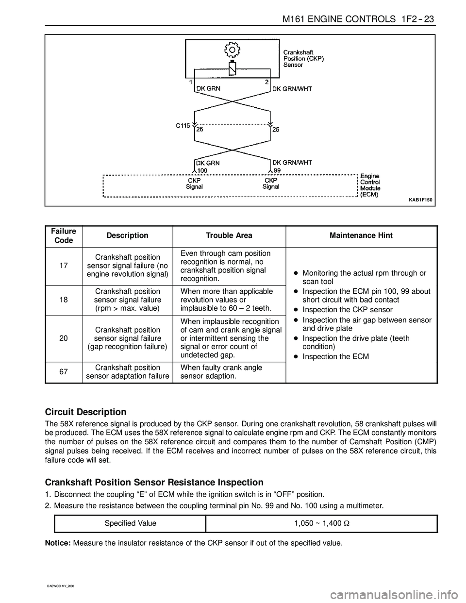
The 58X reference signal is produced by the CKP sensor. During one crankshaft revolution, 58 crankshaft pulseswill
be produced. The ECM uses the 58X reference signal to calculate engine rpm and CKP. The ECM constantly monitors
the number of pulses on the 58X reference circuit and compares them to the number of Camshaft Position (CMP)
signal pulses being received. If the ECM receives and incorrect number of pulses on the 58X reference circuit, this
failure code will set.
Crankshaft Position Sensor Resistance Inspection
1. Disconnect the coupling “E” of ECM while the ignition switch is in “OFF” position.
2. Measure the resistance between the coupling terminal pin No. 99 and No. 100 using a multimeter.
Specified Value
1,050 ~ 1,400Ω
Notice:Measure the insulator resistance of the CKP sensor if out of the specified value.
Page 444 of 2053
1F2 -- 24 M161 ENGINE CONTROLS
D AEW OO M Y_2000
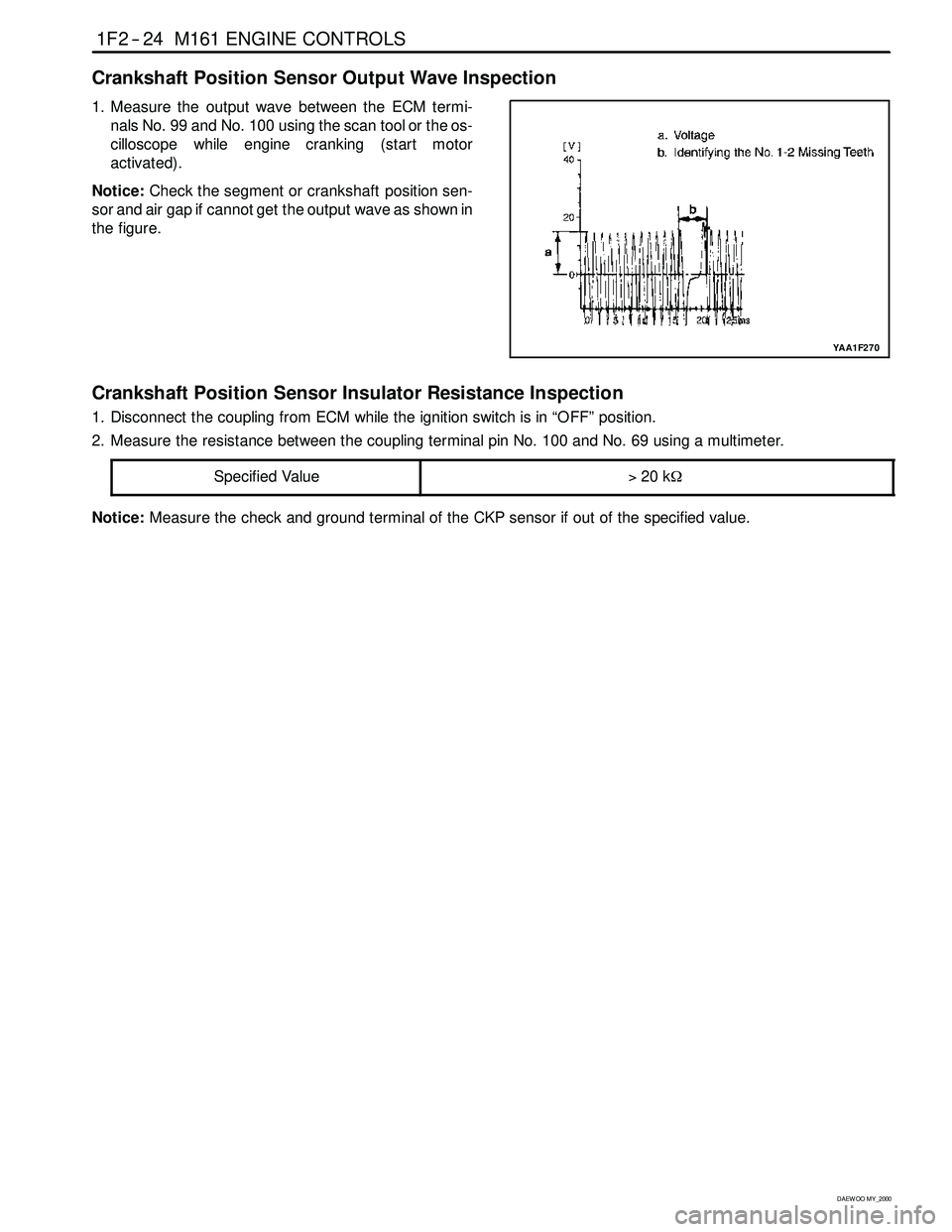
Crankshaft Position Sensor Output Wave Inspection
1. Measure the output wave between the ECM termi-
nals No. 99 and No. 100 using the scan tool or the os-
cilloscope whileengine cranking (start motor
activated).
Notice:Check the segment or crankshaft position sen-
sor and air gap if cannot get the output wave as shown in
the figure.
YAA1F270
Crankshaft Position Sensor Insulator Resistance Inspection
1. Disconnect the coupling from ECM while the ignition switch is in “OFF” position.
2. Measure the resistance between the coupling terminal pin No. 100 and No. 69 using a multimeter.
Specified Value
>20 kΩ
Notice:Measure the check and ground terminal of the CKP sensor if out of the specified value.
Page 446 of 2053
1F2 -- 26 M161 ENGINE CONTROLS
D AEW OO M Y_2000
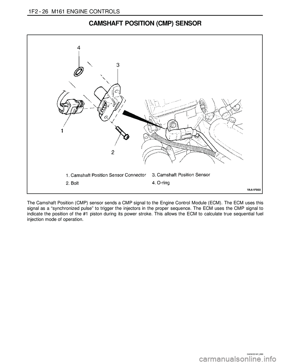
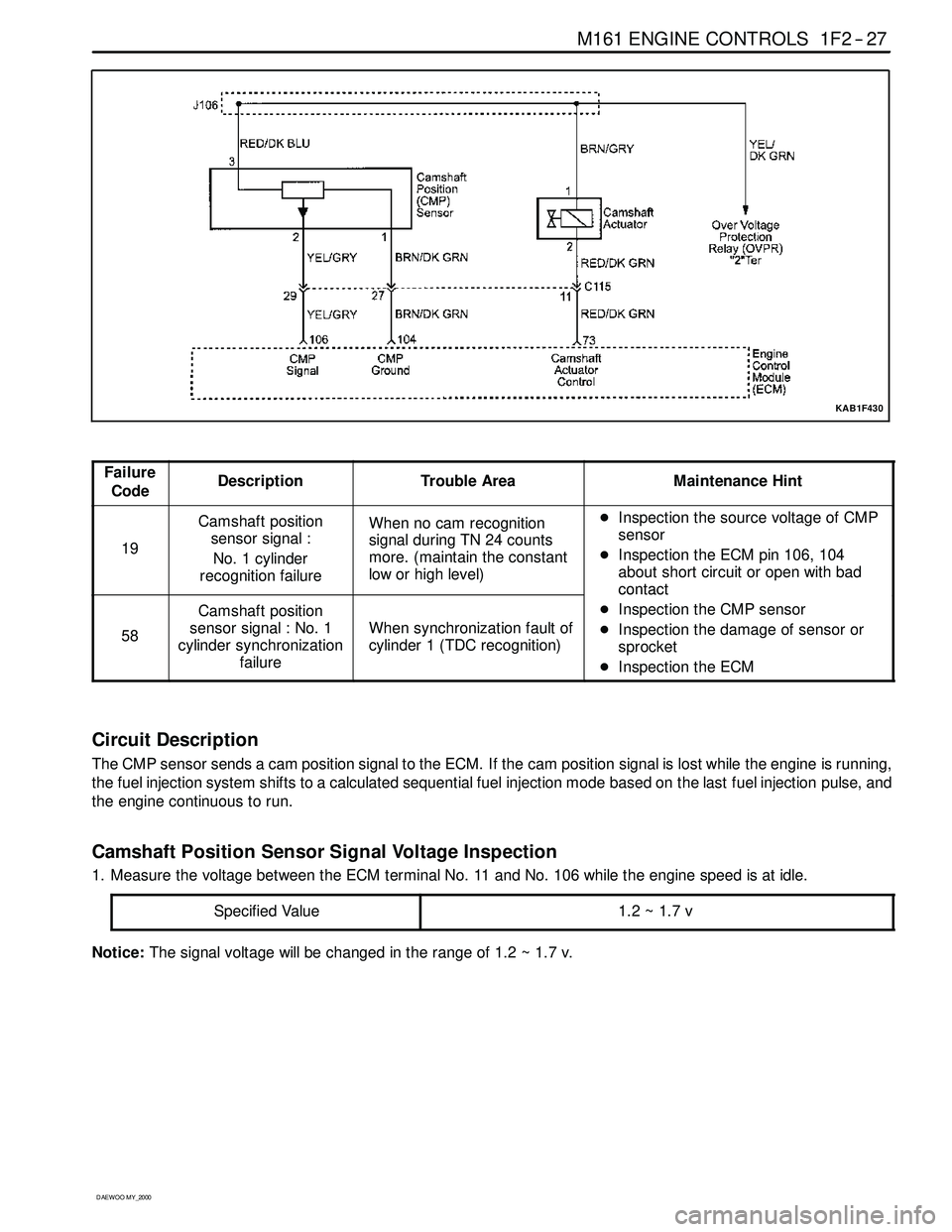
CAMSHAFT POSITION (CMP) SENSOR
YAA1F950
The Camshaft Position (CMP) sensor sends a CMP signal to the Engine Control Module (ECM). The ECM uses this
signal as a “synchronized pulse” to trigger the injectors in the proper sequence. The ECM uses the CMP signal to
indicate the position of the #1 piston during its power stroke. This allows the ECM to calculate true sequential fuel
injection mode of operation.
Page 447 of 2053
M161 ENGINE CONTROLS 1F2 -- 27
D AEW OO M Y_2000
KAB1F430
Failure
CodeDescriptionTrouble AreaMaintenance Hint
19
Camshaft position
sensor signal :
No. 1 cylinder
recognition failureWhen no cam recognition
signal during TN 24 counts
more. (maintain the constant
low or high level)DInspection the source voltage of CMP
sensor
DInspection the ECM pin 106, 104
about short circuit or open with bad
contact
58
Camshaft position
sensor signal : No. 1
cylinder synchronization
failure
When synchronization fault of
cylinder 1 (TDC recognition)
contact
DInspection the CMP sensor
DInspection the damage of sensor or
sprocket
DInspection the ECM
Circuit Description
The CMP sensor sends a cam position signal to the ECM. If the cam position signal is lost while the engine is running,
the fuel injection system shifts to a calculated sequential fuel injection mode based on the last fuel injection pulse, and
the engine continuous to run.
Camshaft Position Sensor Signal Voltage Inspection
1. Measure the voltage between the ECM terminal No. 11 and No. 106 while the engine speed is at idle.
Specified Value
1.2~1.7v
Notice:The signal voltagewill be changed in the range of 1.2 ~ 1.7 v.
Page 448 of 2053
1F2 -- 28 M161 ENGINE CONTROLS
D AEW OO M Y_2000
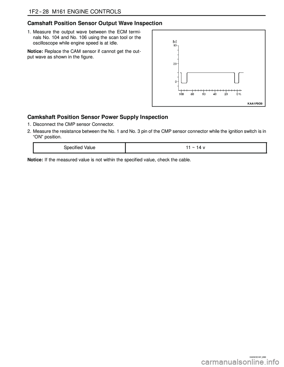
Camshaft Position Sensor Output Wave Inspection
1. Measure the output wave between the ECM termi-
nals No. 104 and No. 106 using the scan tool or the
oscilloscope whileengine speed is at idle.
Notice:Replace the CAM sensor if cannot get the out-
put wave as shown in the figure.
KAA1F0O0
Camkshaft Position Sensor Power Supply Inspection
1. Disconnect the CMP sensor Connector.
2. Measure the resistance between the No. 1 and No. 3 pin of the CMP sensor connector while the ignition switch is in
“ON” position.
Specified Value
11 ~ 14 v
Notice:If the measured value is not within the specified value, check the cable.
Page 450 of 2053
1F2 -- 32 M161 ENGINE CONTROLS
D AEW OO M Y_2000
KNOCK SENSOR (KS)
YAA1F320
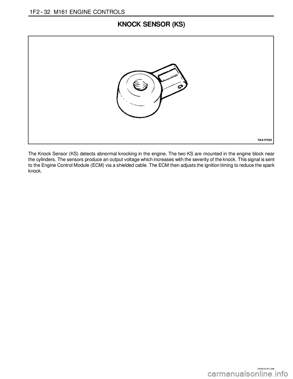
The Knock Sensor (KS) detects abnormal knocking in the engine. The two KS are mounted in the engine block near
the cylinders. The sensors produce an output voltage which increases with the severity of the knock. This signal is sent
to the Engine Control Module (ECM) via a shielded cable. The ECM then adjusts the ignition timing to reduce the spark
knock.
Page 451 of 2053
M161 ENGINE CONTROLS 1F2 -- 33
D AEW OO M Y_2000
KAB1F440
Failure
CodeDescriptionTrouble AreaMaintenance Hint
56No. 1 knock sensor
signal failure
When recognition in more
than control gain threshold at
normal operational condition
of other system during over
75 and 3,000 rpm running
area (cylinder 1, 2, 3, 4)DInspection the ECM pin 118, 117 about
short circuit or open with bad contact
DInspection the KS 1 malfunction
DInspection the ECM
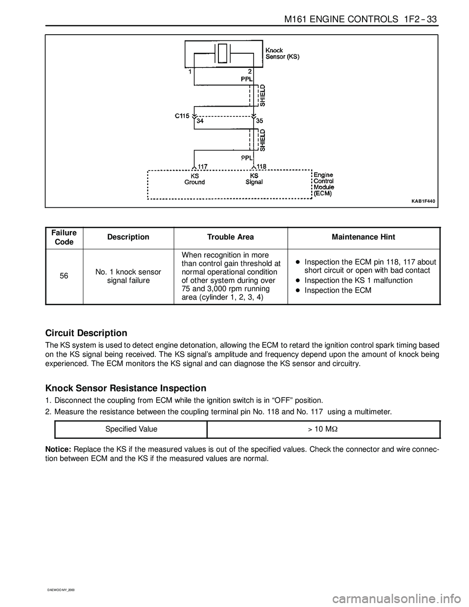
Circuit Description
The KS system is used to detect engine detonation, allowing the ECM to retard the ignition control spark timing based
on the KS signal being received. The KS signal’s amplitude and frequency depend upon the amount of knock being
experienced. The ECM monitors the KS signal and can diagnose the KS sensor and circuitry.
Knock Sensor Resistance Inspection
1. Disconnect the coupling from ECM while the ignition switch is in “OFF” position.
2. Measure the resistance between the coupling terminal pin No. 118 and No. 117 using a multimeter.
Specified Value
>10 MΩ
Notice:Replace the KS if the measured values is out of the specified values. Check the connector and wire connec-
tion between ECM and the KS if the measured values are normal.
Page 453 of 2053
M161 ENGINE CONTROLS 1F2 -- 35
D AEW OO M Y_2000
KAB1F450
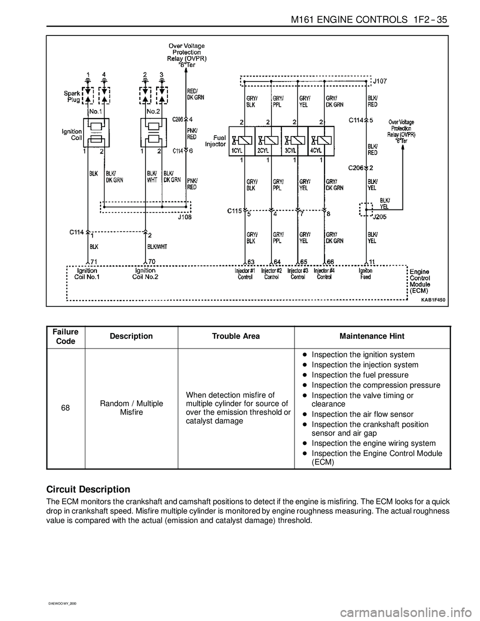
Failure
CodeDescriptionTrouble AreaMaintenance Hint
68Random / Multiple
Misfire
When detection misfire of
multiple cylinder for source of
over the emission threshold or
catalyst damage
DInspection the ignition system
DInspection the injection system
DInspection the fuel pressure
DInspection the compression pressure
DInspection the valve timing or
clearance
DInspection the air flow sensor
DInspection the crankshaft position
sensor and air gap
DInspection the engine wiring system
DInspection the Engine Control Module
(ECM)
Circuit Description
The ECM monitors the crankshaft and camshaft positions to detect if the engine is misfiring. The ECM looks for a quick
drop in crankshaft speed. Misfire multiple cylinder is monitored by engine roughness measuring. The actual roughness
value is compared with the actual (emission and catalyst damage) threshold.
Page 458 of 2053
1F2 -- 40 M161 ENGINE CONTROLS
D AEW OO M Y_2000
FUEL SYSTEM
The function of the fuel metering system is to deliver the correct amount of fuel to the engine under all operating condi-
tions. The fuel is delivered to the engine by the individual fuel injectors mounted into the intake manifold near each
cylinder.
The main fuel control sensors are the Mass Air Flow (MAF) sensor and the oxygen (O2) sensors.
The MAF sensor monitors the mass flow of the air being drawn into the engine. An electrically heated element is
mounted in the intake air stream, where it is cooled by the flow of incoming air. Engine Control Module (ECM) modu-
lates the flow of heating current to maintain the temperature differential between the heated film and the intake air at a
constant level. The amount of heating current required to maintain the temperature thus provides an index for the
mass air flow. This concept automatically compensates for variations in air density, as this is one of the factors that
determines the amount of warmth that the surrounding air absorbs from the heated element. MAF sensor is located
between the air filter and the throttle valve.
Under high fuel demands, the MAF sensor reads a high mass flow condition, such as wide open throttle. The ECM
uses this information to enrich the mixture, thus increasing the fuel injector on-- time, to provide the correct amount of
fuel. When decelerating, the mass flow decreases. This mass flow change is sensed by the MAF sensor and read by
the ECM, which then decreases the fuel injector on-- time due to the low fuel demand conditions.
The O2 sensors are located in the exhaust pipe before catalytic converter. The O2 sensors indicate to the ECM the
amount of oxygen in the exhaust gas, and the ECM changes the air/fuel ratio to the engine by controlling the fuel
injectors. The best air/fuel ratio to minimize exhaust emissions is 14.7 to 1, which allows the catalytic converter to
operate most efficiently. Because of the constant measuring and adjusting of the air/fuel ratio, the fuel injection system
is called a “closed loop” system.
The ECM uses voltage inputs from several sensors to determine how much fuel to provide to the engine. The fuel is
delivered under one of several conditions, called ‘‘modes”.
Starting Mode
When the ignition is turned ON, the ECM turns the fuel pump relay on for 1 second. The fuel pump then builds fuel
pressure. The ECM also checks the Engine Coolant Temperature (ECT) sensor and the Throttle Position (TP) sensor
and determines the proper air/fuel ratio for starting the engine. This ranges from 1.5 to 1 at -- 36°C(--33°F) coolant
temperature to 14.7 to 1 at 94°C (201°F) coolant temperature. The ECM controls the amount of fuel delivered in the
starting mode by changing how long the fuel injector is turned on and off. This is done by ‘‘pulsing” the fuel injectors for
very short times.
Run Mode
The run mode has two conditions called ‘‘open loop” and ‘‘closed loop”.
Open Loop
When the engine is first started and it is above 690 rpm, thesystem goes into “open loop” operation. In “open loop”, the
ECM ignores the signal from the HO2S and calculates the air/fuel ratio based on inputs from the ECT sensor and the
MAF sensor. The ECM stays in “open loop” until the following conditions are met:
DThe O2 has a varying voltage output, showing that it is hot enough to operate properly.
DThe ECT sensor is above a specified temperature (22.5°C).
DA specific amount of time has elapsed after starting the engine.
Closed Loop
The specific values for the above conditions vary with different engines and are stored in the Electronically Erasable
Programmable Read -- Only Memory (EEPROM). When these conditions are met, thesystem goes into “closed loop”
operation. In “closed loop”, the ECM calculates the air/fuel ratio (fuel injector on-- time) based on the signals from the
O2 sensors. This allows the air/fuel ratio to stay very close to 14.7 to 1.
Acceleration Mode
The ECM responds to rapid changes in throttle position and airflow and provides extra fuel.
Deceleration Mode
The ECM responds to changes in throttle position and airflow and reduces the amount of fuel. When deceleration is
very fast, the ECM can cut off fuel completely for short periods of time.