sensor SSANGYONG KORANDO 1997 Service Repair Manual
[x] Cancel search | Manufacturer: SSANGYONG, Model Year: 1997, Model line: KORANDO, Model: SSANGYONG KORANDO 1997Pages: 2053, PDF Size: 88.33 MB
Page 533 of 2053

1G2 -- 10 M161 ENGINE INTAKE & EXHAUST
D AEW OO M Y_2000
EXHAUST MANIFOLD
1 Oxygen Sensor 55 NSm (41 lb-ft) ............
2 Bolt (4 pieces) 9-- 11 NSm (80-- 97 lb-in) ........
3 Upper Cover
4 Nut (11 pieces)
31.5-- 38.5 NSm (23.2-- 28.4 lb-ft) .............5 Exhaust Manifold
6 Flange Bolt & Exhaust Pipe
Mounting Nut 30 NSm (22 lb-ft) ..............
7 Gasket Replace...........................
Page 534 of 2053

M161 ENGINE INTAKE & EXHAUST 1G2 -- 11
D AEW OO M Y_2000
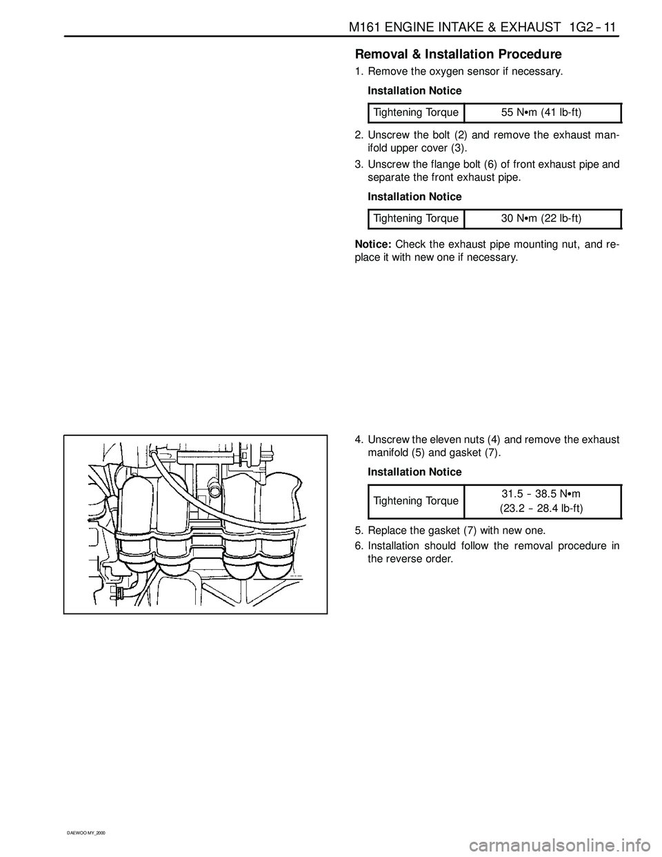
Removal & Installation Procedure
1. Remove the oxygen sensor if necessary.
Installation Notice
Tightening Torque
55 NSm (41 lb-ft)
2. Unscrew the bolt (2) and remove the exhaust man-
ifold upper cover (3).
3. Unscrew the flange bolt (6) of front exhaust pipe and
separate the front exhaust pipe.
Installation Notice
Tightening Torque
30 NSm (22 lb-ft)
Notice:Check the exhaust pipe mounting nut, and re-
place it with new one if necessary.
4. Unscrew the eleven nuts (4) and remove the exhaust
manifold (5) and gasket (7).
Installation Notice
Tightening Torque
31.5 -- 38.5 NSm
(23.2 -- 28.4 lb-ft)
5. Replace the gasket (7) with new one.
6. Installation should follow the removal procedure in
the reverse order.
Page 551 of 2053

D AEW OO M Y_2000
SECTION 1B3
OM600 ENGINE MECHANICAL
CAUTION: Disconnect the negative battery cable before removing or installing any electrical unit or when a
tool or equipment could easily come in contact with exposed electrical terminals. Disconnecting this cable
will help prevent personal injury and damage to the vehicle. The ignition must also be in LOCK unless
otherwise noted.
TABLE OF CONTENTS
Specifications 1B3 -- 2............................
Fastener Tightening Specifications 1B3 -- 2..........
Special Tools 1B3 -- 4.............................
Special Tools Table 1B3-- 4.......................
Maintenance and Repair 1B3 -- 12..................
On-- Vehicle Service 1B3-- 12........................
Engine Assembly 1B3-- 12........................
Poly V-- Belt 1B3 -- 21.............................
Tensioning Device 1B3-- 23.......................
Poly V-- Belt Alignment & Inspection 1B3-- 26........
Prechamber 1B3-- 29............................
Milling of Prechamber Sealing Surface 1B3 -- 32.....
TDC (TDC Sensor Bracket) Setting 1B3 -- 35........
Cylinder Head 1B3-- 37...........................
Timing Case Cover 1B3 -- 63......................
Crankshaft End Cover 1B3-- 71...................
Vibration Damper and Hub 1B3-- 74...............
Crankshaft Front Radial Seal 1B3-- 80.............
Crankshaft Ball Bearing 1B3-- 82..................
Crankshaft 1B3-- 83.............................
Flywheel 1B3 -- 93...............................
Machining of Flywheel 1B3-- 97...................
Flywheel Ring Gear 1B3 -- 98......................
Hydraulic Valve Clearance Compensation
Element Check 1B3-- 101.........................
Valve Tappets 1B3-- 103..........................
Valve Spring Check 1B3-- 105.....................Valve Springs (Cylinder Head Removed) 1B3-- 106..
Valve Springs (Cylinder Head Installed) 1B3-- 109...
Valve Stem Seals 1B3-- 112......................
Check and Replacement of Valve Guides 1B3-- 116..
Valve Seat Rings 1B3-- 122.......................
Check and Machining of Valves 1B3-- 127..........
Machining of Valve Seat 1B3-- 132.................
Camshaft Timing Test 1B3-- 137...................
Camshaft 1B3-- 139.............................
Chain Tensioner 1B3-- 145........................
Timing Chain 1B3-- 147...........................
Tensioning Rail 1B3-- 151.........................
Cylinder Head Guide Rail 1B3-- 152................
Timing Case Cover Guide Rail 1B3-- 156...........
Crankshaft Sprocket 1B3-- 158....................
Piston 1B3-- 163.................................
Oil Filter 1B3-- 169...............................
Oil Pan 1B3-- 171................................
Oil Spray Nozzle 1B3-- 174.......................
Oil Pump 1B3-- 175..............................
Unit Repair 1B3 -- 177............................
Cylinder Head Pressure Leakage Test 1B3-- 177....
Facing Cylinder Head Mating Surface 1B3 -- 178.....
Replacement of Crankcase Core Plug 1B3-- 180.....
Facing Crankcase Contacting Surface 1B3 -- 182....
Oil Gallery Steel Ball 1B3-- 183....................
Cylinder Bore Measurement 1B3-- 187.............
Page 554 of 2053

OM600 ENGINE MECHANICAL 1B3 -- 5
D AEW OO M Y_2000
SPECIAL TOOLS TABLE (Cont’d)
116 589 03 07 00
T Type Socket Wrench
601 589 00 10 00
Cylinder Head Bolt 102
102 589 12 15 00
(φ17) Drift
617 589 10 21 00
RI Sensor
115 589 34 63 00
602 589 00 25 00
102 589 00 15 00
(φ34) Drift
601 589 05 14 00
Assembly Cage
Page 560 of 2053

OM600 ENGINE MECHANICAL 1B3 -- 11
D AEW OO M Y_2000
SPECIAL TOOLS TABLE (Cont’d)
000 589 14 21 00
Tester
001 589 65 09 00
Serration Wrench
000 589 00 68 00
Cleaning Set
601 589 05 21 00
Looking Screw
601 589 00 08 00
Flange
116 589 02 34 00
Thread Bolt
667 589 04 63 00
Retaining Plate
617 589 08 21 00
Position Sensor
Page 567 of 2053

1B3 -- 18 OM600 ENGINE MECHANICAL
D AEW OO M Y_2000
27. Disconnect the preheating time relay sensor plug.
28. Disconnect the coolant temperature sensor plug.
29. Disconnect the accelerator cable from the control
linkage.
Installation Notice
Tightening Torque8--18 N∙m (6 -- 13 lb-ft)
30. Loosen the connection of control pressure cable (an
arrow) used in auto transmisson.
Page 584 of 2053

OM600 ENGINE MECHANICAL 1B3 -- 35
D AEW OO M Y_2000
TDC (TDC SENSOR BRACKET) SETTING
Preceding Work : Removal of No.1 cylinder prechamber
1 Measuring Device
2 Dial Gauge
3 Cylinder Head
4 Piston Set at TDC........................
Tools Service
001589322100 DialGauge
601 589 07 21 00 Depth Gauge
667589012100 FixingDevice
Notice
DThe TDC sensor bracket must be adjusted in case
of followings.
DWhen replacing the TDC sensor bracket.
DWhen replacing the crankshaft, the hub or the
vibration damper.
DlWhen replacing or installing the timing case cover.
DAfter engine overhauling.
* If the cylinder head is removed, the measuring pin of
the dial gauge can be positioned on the piston
crown.
This is done by placing the magnetic dial holder on
the mating surface of the crankcase.
Page 585 of 2053

1B3 -- 36 OM600 ENGINE MECHANICAL
D AEW OO M Y_2000
Setting (with cylinder head installed)
1. Remove the prechamber of No. 1 cylinder.
2. Position the piston of No.1 cylinder at BTDC 10.
3. Install the measuring device into the prechamber
bore and position the dial gauge with a preload of
5mm.
Dial Gauge 001 589 53 21 00
Depth Gauge 601 589 07 21 00
4. Slowly rotate the crankshaft in the direction of en-
gine rotation until the large pointer on the dial gauge
stops (TDC position).
Notice
The position of TDC is when the large pointer on the
dial gauge is stopped before moving back.
5. Remove the reinstall the measuring device and
position the dial gauge scale at ’0’.
6. Slowly rotate the crankshaft in the direction of en-
gine rotation until the dial gauge has moved back
(counterclockwise) by 3.65mm.
7. Insert fixing device into the sensor bracket.
Notice
The pin on the vibration damper must engage into
the slot of the fixing device.
Fixing Device 667 589 01 21 00
8. If the pin does not engage, adjust the setting of the
sensor bracket by removing and tightening of the
sensor bracket bolts.
Tightening Torque10 N∙m(89lb-in)
Notice
The timing mark on the damper must be positioned
at ATDC 20.
Page 593 of 2053

1B3 -- 44 OM600 ENGINE MECHANICAL
D AEW OO M Y_2000
22. Remove the cable channel.
23 .Disconnect the cables from the glow plug sensor
and coolant temperature sensor.
24. Remove the heater pipe bracket from the oil filter.
25. Pry off the clamp and push the heater feed pipe for-
ward and then pull out the pipe.
Page 609 of 2053

1B3 -- 60 OM600 ENGINE MECHANICAL
D AEW OO M Y_2000
33. Replace the gasket and install the cylinder head
cover.
Tightening Torque10 N∙m(89lb-in)
34. Install the blow-- by hose.
35. Connect the wires to the coolant temperature sen-
sor and the glow plug sensor.
36. Replace the intake manifold gasket.
37. Install the intake manifold.
Tightening Torque25 N∙m (18 lb-ft)