STARTER MOTOR SSANGYONG KORANDO 1997 Service Repair Manual
[x] Cancel search | Manufacturer: SSANGYONG, Model Year: 1997, Model line: KORANDO, Model: SSANGYONG KORANDO 1997Pages: 2053, PDF Size: 88.33 MB
Page 43 of 2053

M162 ENGINE MECHANICAL 1B1 -- 11
D AEW OO M Y_2000
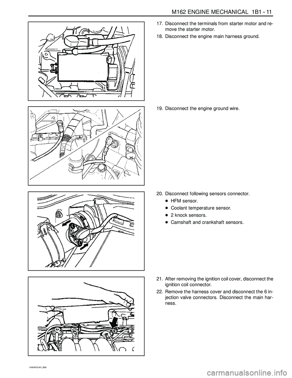
17. Disconnect the terminals from starter motor and re-
move the starter motor.
18. Disconnect the engine main harness ground.
19. Disconnect the engine ground wire.
20. Disconnect following sensors connector.
DHFM sensor.
DCoolant temperature sensor.
D2 knock sensors.
DCamshaft and crankshaft sensors.
21. After removing the ignition coil cover, disconnect the
ignition coil connector.
22. Remove the harness cover and disconnect the 6 in-
jection valve connectors. Disconnect the main har-
ness.
Page 118 of 2053

1B1 -- 92 M162 ENGINE MECHANICAL
D AEW OO M Y_2000
OIL FILTER
Preceding Work: Removal of starter motor
Removal of upper intake manifold
1 Coolant Line
2 O -- ring Replace............................
3 Clip
4Hose5Bolt 25NSm (18 lb-ft) ......................
6 Oil Filter
7 Gasket Replace...........................
Page 154 of 2053

1E 1 -- 2 M162 ENGINE ELECTRICAL
D AEW OO M Y_2000
SPECIFICATIONS
GENERATOR SPECIFICATIONS
ApplicationDescription
Current11 5 A
Output Voltage12 -- 14 v
Resistance Between Rotor Core and Slip Ring∞Ω
STARTER SPECIFICATIONS
ApplicationDescription
Output Power1.8 kw
Voltage12 v
BATTERY SPECIFICATIONS
ApplicationDescription
Capacity90 AH
Max. Tolerance Between Cells≥0.04
Specific Gravity≥1.24
FASTER TIGHTENING SPECIFICATIONS
ApplicationNSmLb-FtLb-In
Generator Terminal B+Nut14 -- 1810 -- 13--
Generator Terminal D+Nut4--5--35 -- 44
Generator Mounting Bolt2518--
Battery Cable Nut on Starting Motor12 -- 159--11--
Electric Wire Nut on Starting Motor6--7--53 -- 62
Starting Motor Mounting Bolt35 -- 4826 -- 35--
Battery Mounting Bracket Nut12 -- 189--13--
Battery Negative Cable12 -- 189--13--
Battery Positive Cable12 -- 189--13--
Spark Plug Cover Bolt9--11--80 -- 97
Ignition Cable Bolt9--11--80 -- 97
Spark plug20 -- 3015 -- 22--
Page 304 of 2053

M161 ENGINE MECHANICAL 1B2 -- 11
D AEW OO M Y_2000
15. Disconnect the terminals from starter motor and re-
move the starter motor.
16. Disconnect the engine main harness ground.
17. Disconnect the engine ground wire.
18. Disconnect following sensors connector.
DHFM sensor.
DCoolant temperature sensor.
DKnock sensor.
DCamshaft and crankshaft sensors.
19. After removing the ignition coil cover, disconnect the
ignition coil connector.
20. Remove the harness cover and disconnect the 4 in-
jection valve connectors. Disconnect the main har-
ness.
Page 413 of 2053

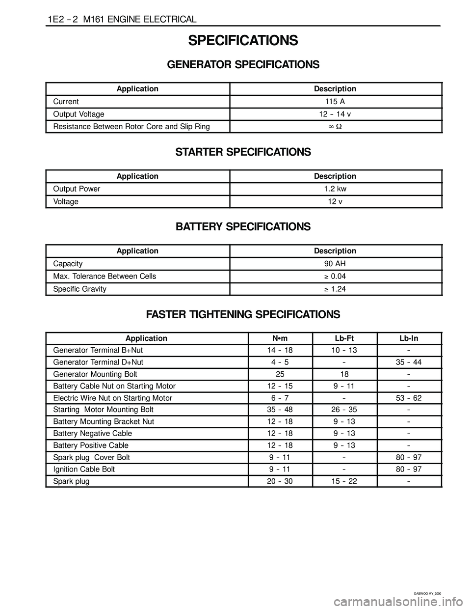
1E 2 -- 2 M161 ENGINE ELECTRICAL
D AEW OO M Y_2000
SPECIFICATIONS
GENERATOR SPECIFICATIONS
ApplicationDescription
Current11 5 A
Output Voltage12 -- 14 v
Resistance Between Rotor Core and Slip Ring∞Ω
STARTER SPECIFICATIONS
ApplicationDescription
Output Power1.2 kw
Voltage12 v
BATTERY SPECIFICATIONS
ApplicationDescription
Capacity90 AH
Max. Tolerance Between Cells≥0.04
Specific Gravity≥1.24
FASTER TIGHTENING SPECIFICATIONS
ApplicationNSmLb-FtLb-In
Generator Terminal B+Nut14 -- 1810 -- 13--
Generator Terminal D+Nut4--5--35 -- 44
Generator Mounting Bolt2518--
Battery Cable Nut on Starting Motor12 -- 159--11--
Electric Wire Nut on Starting Motor6--7--53 -- 62
Starting Motor Mounting Bolt35 -- 4826 -- 35--
Battery Mounting Bracket Nut12 -- 189--13--
Battery Negative Cable12 -- 189--13--
Battery Positive Cable12 -- 189--13--
Spark plug Cover Bolt9--11--80 -- 97
Ignition Cable Bolt9--11--80 -- 97
Spark plug20 -- 3015 -- 22--
Page 420 of 2053

M161 ENGINE ELECTRICAL 1E 2 -- 9
D AEW OO M Y_2000
Removal & Installation Procedure
1. Disconnect the battery negative cable.
2. Unscrew the 3 screws and remove the ignition cable
duct cover.
Installation Notice
Tightening Torque
9--11NSm (80 -- 97 lb-in)
3. Seperate the cable from the ignition cable and the
spark plug.
4. Remove the 2 bolts from each ignition cable and re-
move the ignition cables.
Installation Notice
Tightening Torque
9--11NSm (80 -- 97 lb-in)
Install the ignition cable to the cylinder 2 and 4 and
connect the cable from 1 to 4, and from 2 to 3.
-- T1/1 : Cylinder 1 and 4
-- T1/2 : Cylinder 2 and 3
5. Installation should follow the removal procedure in
the reverse order.
Ignition Cable and Cable Lay- out
1. Firing Order : 1 -- 3 -- 4 -- 2
2. T1/1 : Connect the cylinder 1 + 4
3. T1/2 : Connect the cylinder 2 + 3
Inspection & Maintenance (for E2.3 MSE)
1. Measure the primary resistance between the cable
terminals 1 and 15 after removing the ignition cable
wiring connector (1 and 15) with ignition switch OFF.
Notice:Replace the ignition coil if out of the specified
resistance.
Specified Value
0.9 -- 1.6Ω
2. Measure the primary voltage(T1/1) between the ECU
terminals No.72 and No.69 during the engine crank-
ing (starter motor activated).
Specified Value
200 -- 350 v
Page 547 of 2053

1A3 -- 12 GENERAL ENGINE INFORMATION
D AEW OO M Y_2000
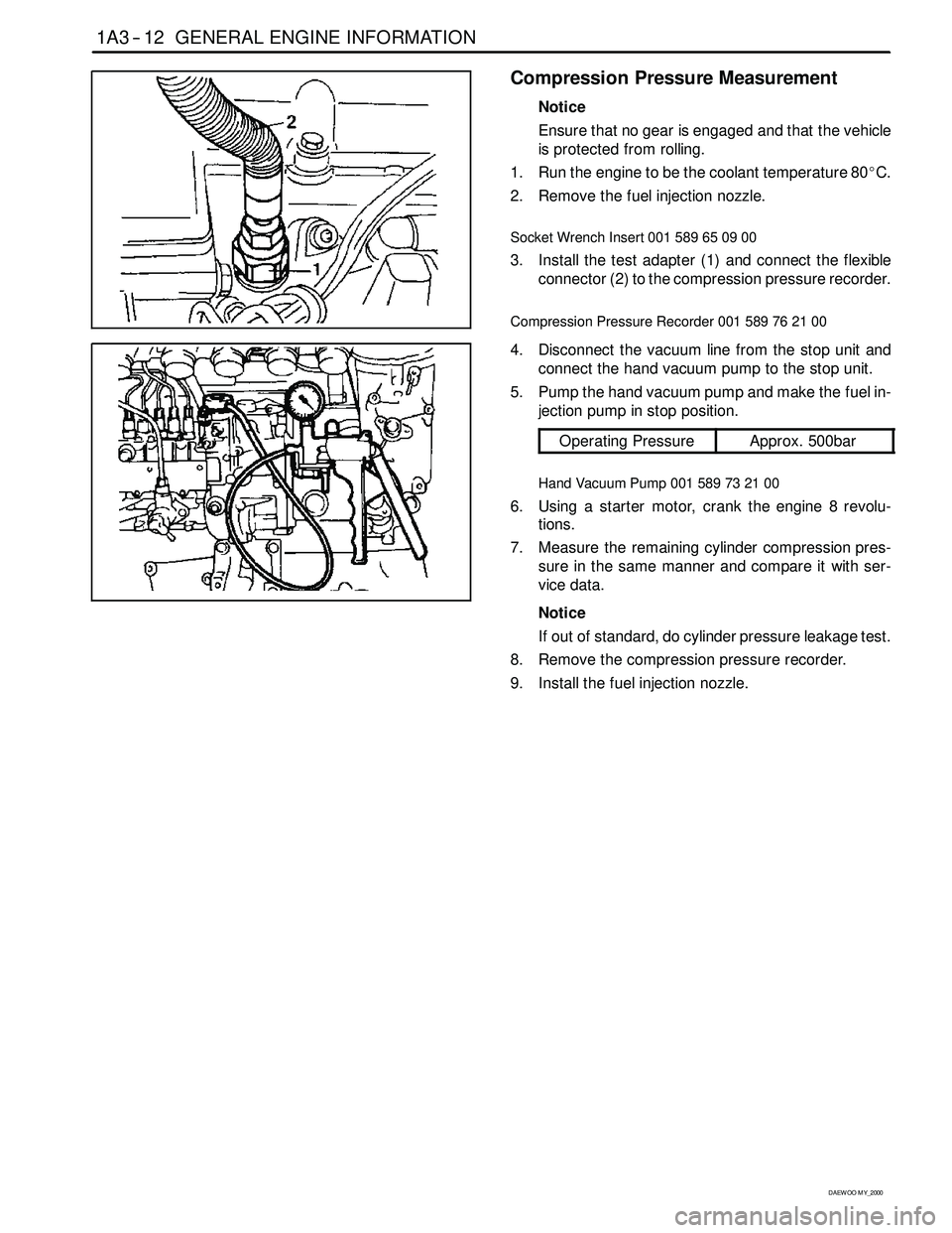
Compression Pressure Measurement
Notice
Ensure that no gear is engaged and that the vehicle
is protected from rolling.
1. Run the engine to be the coolant temperature 80_C.
2. Remove the fuel injection nozzle.
Socket Wrench Insert 001 589 65 09 00
3. Install the test adapter (1) and connect the flexible
connector (2) to the compression pressure recorder.
Compression Pressure Recorder 001 589 76 21 00
4. Disconnect the vacuum line from the stop unit and
connect the hand vacuum pump to the stop unit.
5. Pump the hand vacuum pump and make the fuel in-
jection pump in stop position.
Operating PressureApprox. 500bar
Hand Vacuum Pump 001 589 73 21 00
6. Using a starter motor, crank the engine 8 revolu-
tions.
7. Measure the remaining cylinder compression pres-
sure in the same manner and compare it with ser-
vice data.
Notice
If out of standard, do cylinder pressure leakage test.
8. Remove the compression pressure recorder.
9. Install the fuel injection nozzle.
Page 566 of 2053

OM600 ENGINE MECHANICAL 1B3 -- 17
D AEW OO M Y_2000
21. Remove the fuel lines from the fuel filter and cover
the filter with plug.
22. Disconnect the brake booster hose from vacuum
pump.
23. Disconnect the other vacuum lines.
24. Disconnect the ground cable.
25. Disconnect the generator wires.
26. Disconnect the starter motor wires and remove the
starter motor.
Page 583 of 2053

1B3 -- 34 OM600 ENGINE MECHANICAL
D AEW OO M Y_2000
8. Remeasure size ’X’ and compare it with the first
measurement and determine the thickness of
spacer ring.
Ex
Size before machining25.7 mm
Size after machining25.5 mm
The spacer ring should be selected so that it is at
least 0.1mm and not more than 0.3mm thicker than
the measured on the sealing surface. In this exam-
ple, the necessary thickness of spacer ring should
be within 0.3 ~ 0.5mm and the thickness of spacer
ring to be installed is 0.3mm.
9. Remove the countersink tool and clean the chips.
Notice
If the sealing surface is not completely flat, rema-
chine the sealing surface.
10. Remove rag from the prechamber bore and crank
the engine with starter motor to threw out any chips
which may have got into the combustion chamber.
11. Insert the proper spacer ring into the prechamber
sealing surface.
12. Punch a mark on the cylinder head above the pre-
chamber sealing surface which has been machined.
13. Install the prechambers.
Notice
If the cylinder head is removed, the projection ’C’ is
measured in place of size ’X’ and the appropriate
size of spacer ring selected.
Normal Projection (c)7.6 -- 8.1mm
Page 596 of 2053

1B3 -- 46 OM600 ENGINE MECHANICAL
D AEW OO M Y_2000
30. Rotate the crankshaft and set the no.1 cylinder at
TDC.
Notice
Do not rotate the crankshaft to the opposite direc-
tion of engine revolution.
31. Place alignment marks on the camshaft gear and
timing chain.
32. Ensure that the camshaft and the bearing cap mark-
ing are aligned.
33. Remove the starter motor and install the engine lock
onto the flywheel ring gear.
Engine Lock 602 589 00 40 00