check engine SSANGYONG KORANDO 1997 Service Owner's Manual
[x] Cancel search | Manufacturer: SSANGYONG, Model Year: 1997, Model line: KORANDO, Model: SSANGYONG KORANDO 1997Pages: 2053, PDF Size: 88.33 MB
Page 101 of 2053

1B1 -- 74 M162 ENGINE MECHANICAL
D AEW OO M Y_2000
17. Rivet the link pin.
Check the condition and it again if necessary.
18. Install the chain tensioner.
Installation Notice
Ti
ghteningScrew Plug40 NSm
(30 lb-ft)
Tightening
TorqueTensioner
Assembly72 -- 88 NSm
(53 -- 65 lb-ft)
19. Check the camshaft timing position.
Page 102 of 2053

M162 ENGINE MECHANICAL 1B1 -- 75
D AEW OO M Y_2000
TENSIONING RAIL
Preceding Work: Removal of timing gear case cover
1 Tensioning Rail
2 Plastic Guide3 Tensioning Rail Pin
4 Guide Rail
Removal & Installation Procedure
1. Put the assembly mark at the camshaft sprocket and
the timing chain with the paint (arrow).
2. Remove the exhaust camshaft sprocket.
3. Remove the tensioning rail (1) from the tensioning rail
pin (3).
Notice:
DReplace the plastic guide (2) if it is damaged.
DFor installation, exactly align the plastic guide (2) with
the tensioning rail (1).
4. Installation should follow the removal procedure in
the reverse order.
5. Check the camshaft timing position.
Page 103 of 2053

1B1 -- 76 M162 ENGINE MECHANICAL
D AEW OO M Y_2000
CYLINDER HEAD GUIDE RAIL
Preceding Work: Removal of cylinder head front cover
1 Chain Tensioner
2 Upper Guide Rail3 Upper Guide Rail Pin
4 Wrench
Removal & Installation Procedure
1. Remove the chain tensioner (1).
2. Turn the exhaust camshaft to the camshaft rotating
direction using the wrench (4) and loosen the timing
chain at upper guide rail (2).
3. Pull out the upper guide rail pin from the guide rail (2).
4. Turn the exhaust camshaft to the opposite direction
of rotation using the wrench.
5. Check for damages at the upper sliding rail and re-
place it if necessary. Install the upper guide rail pin.
6. Install the chain tensioner.
Installation Notice
Ti
ghteningScrew Plug40 NSm
(30 lb-ft)
Tightening
TorqueTensioner
Assembly72 -- 88 NSm
(53 -- 65 lb-ft)
Page 104 of 2053

M162 ENGINE MECHANICAL 1B1 -- 77
D AEW OO M Y_2000
CRANKCASE GUIDE RAIL
Preceding Work: Removal of timing gear case cover
1 Guide Rail
2 Plastic Guide3 Guide Rail Pin
4 Tensioning Rail
Removal & Installation Procedure
1. Put the assembly mark at the camshaft sprocket and
the timing chain with the paint (arrow).
2. Remove the exhaust camshaft sprocket.
3. Remove the guide rail (1) from the guide rail pin (3).
Notice:
DReplace the plastic guide (2) if damaged.
DConnect the plastic guide (2) and the guide rail (1) by
aligning them accurately when installing.
4. Installation should follow the removal procedure in
the reverse order.
5. Check the camshaft timing position.
Page 108 of 2053

1B1 -- 82 M162 ENGINE MECHANICAL
D AEW OO M Y_2000
Installation Procedure
1. Check the piston ring gap and apply the engine oil to
the piston pin and the connecting rod bushing.
2. Connect the piston and the connecting rod by press-
ing in the piston pin (6) and install the snap ring to the
groove.
3. Clean the cylinder bore, connecting rod bearing jour-
nal, connecting rod bearing shell and the piston and
coat them with engine oil.
4. Install the piston ring.
5. Install the piston so that the arrow on the piston head
faces to the forward of the vehicle.
6. After aligning the connecting rod and the bearing cap
mark (// or a number), tighten the bolts.
Installation Notice
TighteningTorque1st step: 40 NSm (30 lb-ft)TighteningTorque2nd step: 90°
Apply the engine oil to the bearing cap upper and low-
er bearing shells.
7. Check if the crankshaft rotates without any trouble by
rotating it.
Page 110 of 2053

1B1 -- 84 M162 ENGINE MECHANICAL
D AEW OO M Y_2000
Inspection
1. Measure the basic bore of the connecting rod bear-
ing.
Notice:If the basic bore exceeds the value of
51.614mm, replace the bearing or check the connecting
rod.
2. Check connecting rod bolts.
Length When New (L)
51.7 -- 52 mm
Max. Length (L)52.9 mm
Tightening Torque
1st step: 40 NSm
(30 lb-ft)
TighteningTorque
2nd step: 90°
Notice:If the length exceeds max. length, replace it.
3. Check the assembly mark(indication//or number:ar-
row) of the connecting rods and the bearing cap when
installing.
Notice
DMake sure it doesn’t exceed over 4g with other con-
necting rods when replacing the connecting rods.
DCheck if the connecting rod and the bearing cap are
accurately seated on the groove when replacing the
bearing.
Page 114 of 2053

1B1 -- 88 M162 ENGINE MECHANICAL
D AEW OO M Y_2000
OIL PAN
Preceding Work: Removal of front stabilizer
Removal of steering gear box
1 Gasket Replace...........................
2 Bolt (M6 x 22, 6 pieces) 10 NSm (89 lb-in) .....
3 Drain Plug (M6 x 20) 25 NSm (18 lb-ft) .......
4 Bolt (M6 x 20, 22 pieces) 10 NSm (89 lb-in) ....5 Bolt (M6 x 85) 10 NSm (89 lb-in) .............
6 Bolt (M8 x 40) 25 NSm (18 lb-ft) .............
7 Bolt (M10) 40 NSm (30 lb-ft) .................
8OilPan
Removal & Installation Procedure
1. Remove the drain plug and drain the oil completely.
2. Unscrew the bolts and remove the oil pan and gasket.
Notice:Arrange the bolts according to each size.
3. Clean the inside of oil pan and sealing surface, then
apply the sealant.
4. Replace the gasket with new one.
5. Install the oil pan with gasket, and tighten each bolt in
specified torque.
6. Check for oil leaks while running the engine.
Page 117 of 2053

M162 ENGINE MECHANICAL 1B1 -- 91
D AEW OO M Y_2000
8. Temporarily tighten the oil filter cover. Install the oil
filter remover 103 589 02 09 00, and then complete-
ly tighten it.
Installation Notice
Tightening Torque
25 NSm (18 lb-ft)
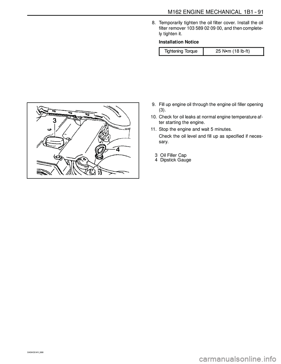
9. Fill up engine oil through the engine oil filler opening
(3).
10. Check for oil leaks at normal engine temperature af-
ter starting the engine.
11. Stop the engine and wait 5 minutes.
Check the oil level and fill up as specified if neces-
sary.
3 Oil Filler Cap
4 Dipstick Gauge
Page 119 of 2053

M162 ENGINE MECHANICAL 1B1 -- 93
D AEW OO M Y_2000
Removal & Installation Procedure
1. Drain the coolant from the crank case.
2. Remove the each coolant line and hose.
3. Remove the oil filter bolt and then remove the oil filter.
Installation Notice
Tightening Torque
25 NSm (18 lb-ft)
Notice:Replace the oil filter gasket.
4. Installation should follow the removal procedure in
the reverse order.
5. Check engine oil level.
6. Run the engine at idle and check the engine for leaks.
Page 124 of 2053

1B1 -- 98 M162 ENGINE MECHANICAL
D AEW OO M Y_2000
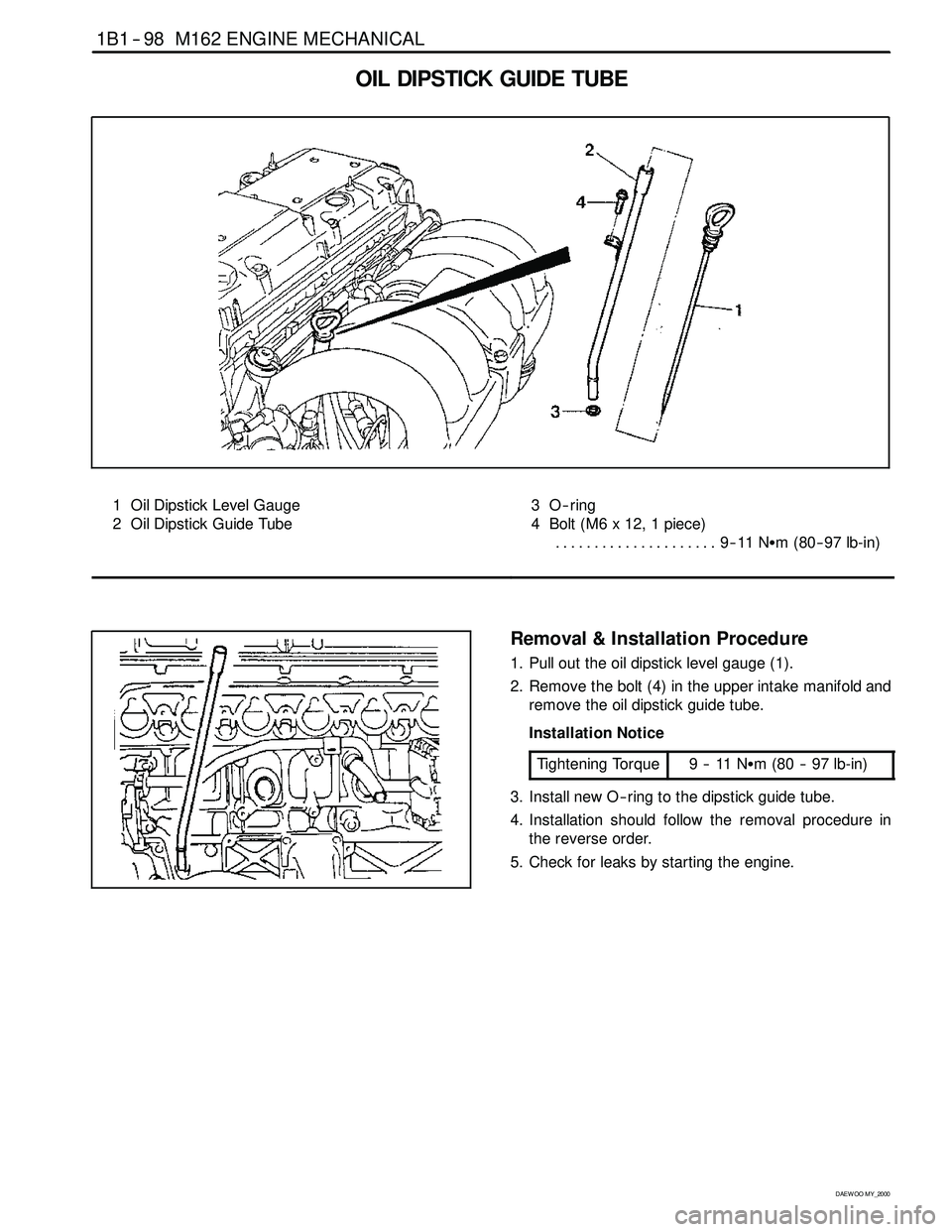
OIL DIPSTICK GUIDE TUBE
1 Oil Dipstick Level Gauge
2 Oil Dipstick Guide Tube3O--ring
4 Bolt (M6 x 12, 1 piece)
9--11 NSm (80-- 97 lb-in) .....................
Removal & Installation Procedure
1. Pull out the oil dipstick level gauge (1).
2. Remove the bolt (4) in the upper intake manifold and
remove the oil dipstick guide tube.
Installation Notice
Tightening Torque
9--11NSm (80 -- 97 lb-in)
3. Install new O -- ring to the dipstick guide tube.
4. Installation should follow the removal procedure in
the reverse order.
5. Check for leaks by starting the engine.