automatic SSANGYONG KORANDO 2012 Service Manual
[x] Cancel search | Manufacturer: SSANGYONG, Model Year: 2012, Model line: KORANDO, Model: SSANGYONG KORANDO 2012Pages: 1082, PDF Size: 96.1 MB
Page 220 of 1082
09-8
(3) Starting with jumper cable
If the battery is weak or terminated, the battery from another vehicle can be used with jumper cables to
start the engine.
Connecting order ▶
The positive (+) terminal of the discharged battery
The positive (+) terminal of the booster battery
The negative (-) terminal of the booster battery
Connect one end of the other jumper cable to the body of the discharged vehicle, such as the
engine block or a front towing hook. 1.
2.
3.
4.
Starting ▶
Prepare a set of jumper cables.
Place another vehicle that has the same 12 V of power near to the discharged vehicle.
Switch off all electrical accessories for the discharged vehicle.
Apply the parking brake and shift the transaxle to the P position (automatic transaxle) or neutral (N)
position (manual transaxle).
Connect the jumper cables.
Try to start the discharged vehicle while accelerating the engine rpm in the booster vehicle.
Attempt to start the engine with the discharged battery.
After starting the engine, carefully disconnect the jumper cables in the reverse sequence of
connection. 1.
2.
3.
4.
5.
6.
7.
8.
Page 250 of 1082

12-38530-00
1. OVERVIEW
1) System Description
The cruise control is an automatic speed control system that maintains a desired driving speed without
using the accelerator pedal.
The vehicle speed must be greater than 38 km/h to engage the cruise control. This feature is especially
useful for motorway driving.
The cruise control system is a supplementary system, which helps the driver to drive the vehicle at a
desired speed without using the accelerator pedal under the traffic condition where the vehicle-to-
vehicle distance meets the legal requirement.
Auto cruise operated ECO cruise operated
Page 258 of 1082
12-118530-00
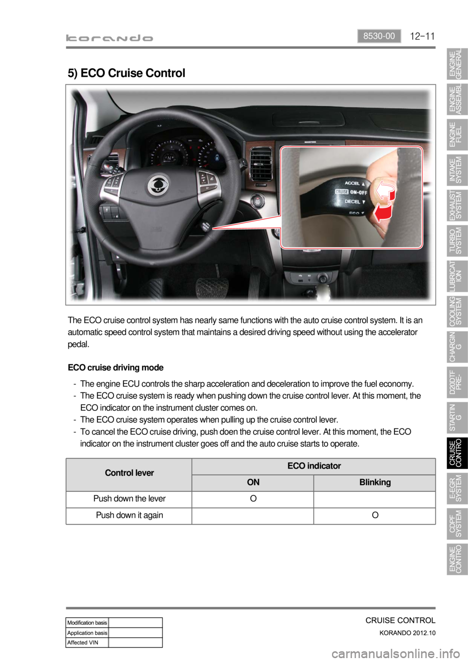
5) ECO Cruise Control
The ECO cruise control system has nearly same functions with the auto cruise control system. It is an
automatic speed control system that maintains a desired driving speed without using the accelerator
pedal.
ECO cruise driving mode
The engine ECU controls the sharp acceleration and deceleration to improve the fuel economy.
The ECO cruise system is ready when pushing down the cruise control lever. At this moment, the
ECO indicator on the instrument cluster comes on.
The ECO cruise system operates when pulling up the cruise control lever.
To cancel the ECO cruise driving, push doen the cruise control lever. At this moment, the ECO
indicator on the instrument cluster goes off and the auto cruise starts to operate. -
-
-
-
Control leverECO indicator
ON Blinking
Push down the lever O
Push down it again O
Page 285 of 1082
15-90000-00
2) ECU Control
(1) Function
a. ECU Function
ECU receives and analyzes signals from various sensors and then modifies those signals into
permissible voltage levels and analyzes to control respective actuators.
ECU microprocessor calculates injection period and injection timing proper for engine piston speed and
crankshaft angle based on input data and stored specific map to control the engine power and emission
gas.
Output signal of the ECU microprocessor drives pressure control valve to control the rail pressure and
activates injector solenoid valve to control the fuel injection period and injection timing; so controls
various actuators in response to engine changes. Auxiliary function of ECU has adopted to reduce
emission gas, improve fuel economy and enhance safety, comforts and conveniences. For example,
there are EGR, booster pressure control, autocruise (export only) and immobilizer and adopted CAN
communication to exchange data among electrical systems (automatic T/M and brake system) in the
vehicle fluently. And Scanner can be used to diagnose vehicle status and defectives.
<00760097008c00990088009b00900095008e0047009b008c00940097008c00990088009b009c0099008c0047009900880095008e008c00470096008d0047006c006a007c00470090009a0047009500960099009400880093009300a000470054005b005700
47009b009600470052005f005c00b6006a004700880095008b> protected from factors like oil,
water and electromagnetism and there should be no mechanical shocks.
To control the fuel volume precisely under repeated injections, high current should be applied instantly
so there is injector drive circuit in the ECU to generate necessary current during injector drive stages.
Current control circuit divides current applying time (injection time) into full-in-current-phase and hold-
current-phase and then the injectors should work very correctly under every working condition.
b. Control Function
Controls by operating stages
To make optimum combustion under every operating stage, ECU should calculate proper injection
volume in each stage by considering various factors.
Starting injection volume control
During initial starting, injecting fuel volume will be calculated by function of temperature and engine
cranking speed. Starting injection continues from when the ignition switch is turned to ignition
position to till the engine reaches to allowable minimum speed.
Driving mode control
If the vehicle runs normally, fuel injection volume will be calculated by accelerator pedal travel and
engine rpm and the drive map will be used to match the drivers inputs with optimum engine power. -
-
-
Page 310 of 1082
15-34
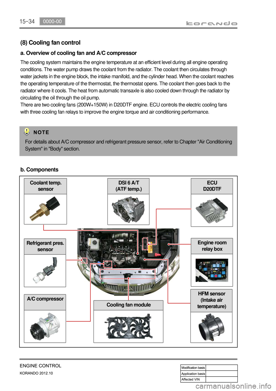
Coolant temp.
sensor
(8) Cooling fan control
a. Overview of cooling fan and A/C compressor
The cooling system maintains the engine temperature at an efficient level during all engine operating
conditions. The water pump draws the coolant from the radiator. The coolant then circulates through
water jackets in the engine block, the intake manifold, and the cylinder head. When the coolant reaches
the operating temperature of the thermostat, the thermostat opens. The coolant then goes back to the
radiator where it cools. The heat from automatic transaxle is also cooled down through the radiator by
circulating the oil through the oil pump.
There are two cooling fans (200W+150W) in D20DTF engine. ECU controls the electric cooling fans
with three cooling fan relays to improve the engine torque and air conditioning performance.
For details about A/C compressor and refrigerant pressure sensor, refer to Chapter "Air Conditioning
System" in "Body" section.
b. Components
Refrigerant pres.
sensor
A/C compressor
ECU
D20DTF DSI 6 A/T
(ATF temp.)
Cooling fan module
HFM sensor
(Intake air
temperature)
Engine room
relay box
Page 331 of 1082
01-70000-00
3) General Instructions
Before lifting up the vehicle with a lift, correctly support the lifting points.
When using a jack, park the vehicle on a level ground and place the wheel chocks under the tires.
Position the jack under the frame and lift up the vehicle and then support with chassis stand before
service work.
Make sure to disconnect the negative (-) cable from the battery to prevent any damage to electric
systems.
If you have to work on vehicle, cover the seats and floor with protection covers to avoid any
damage and contamination.
Brake fluid and anti-freeze can damage the painted surface of body. So carefully handle them
during service work.
To improve the efficiency of service work, use only recommended and specified tools.
Use only Ssangyong genuine spare parts.
Never reuse the cotter pin, gasket, O-ring, oil seal, lock washer and self-locking nut. Replace them
with new ones. If reused, normal functions cannot be maintained.
Store the disassembled parts as a set based on disassembly order and unit.
Pay particular attention not to miss or mix the fasteners.
If necessary, especially for inspection, clean the removed parts completely.
Apply the oil or grease on the running and sliding surfeces before installation. Use the specified
sealant and gasket to prevent leakage if necessary.
Tighten the fasteners to the specified tightening torque.
As a final stage of service work, check if the serviced system is working properly and the problem
has been eliminated clearly. (1)
(2)
(3)
(4)
(5)
(6)
(7)
(8)
(9)
(10)
(11)
(12)
(13)
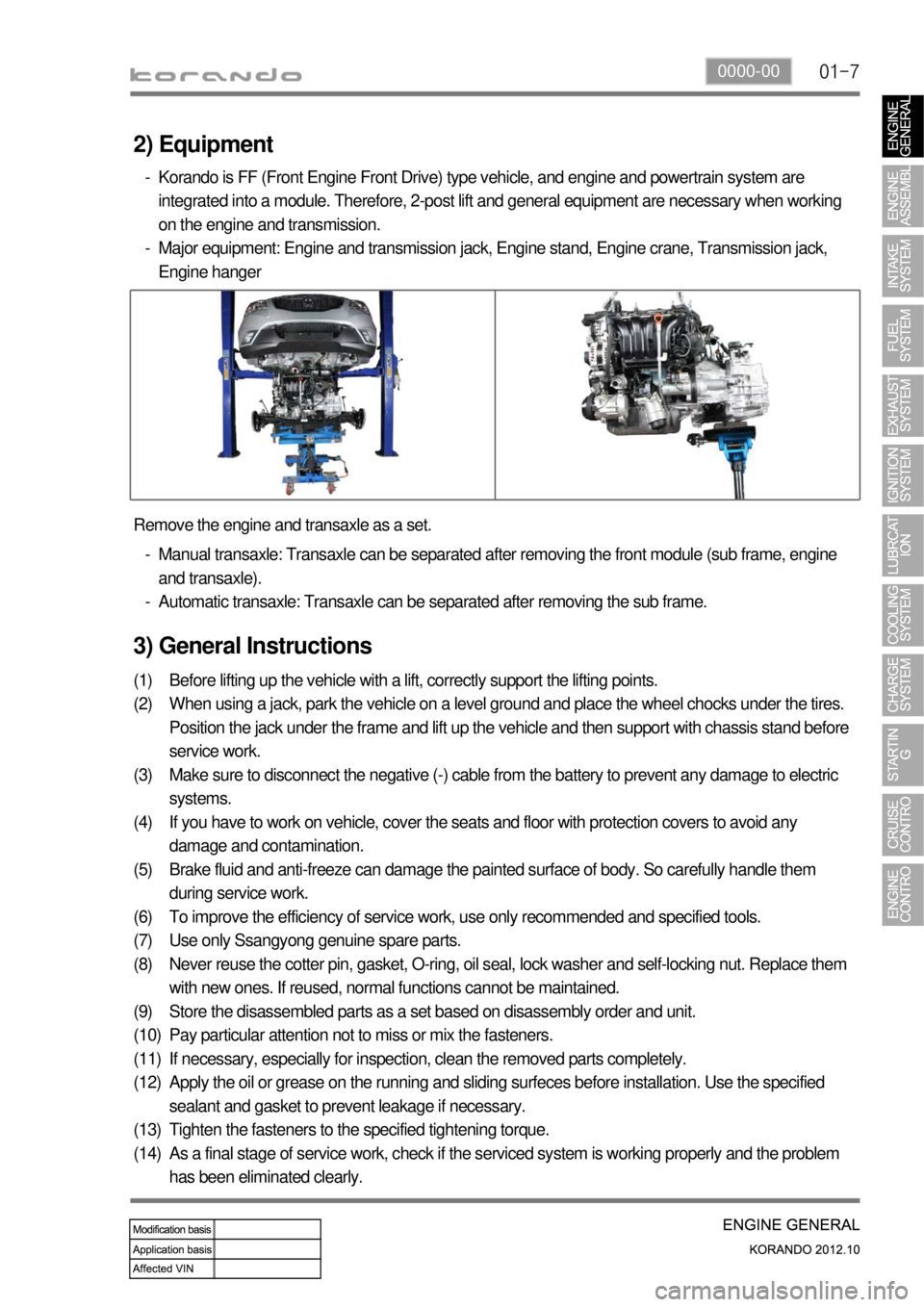
(14) Remove the engine and transaxle as a set.
Manual transaxle: Transaxle can be separated after removing the front module (sub frame, engine
and transaxle).
Automatic transaxle: Transaxle can be separated after removing the sub frame. -
-
2) Equipment
Korando is FF (Front Engine Front Drive) type vehicle, and engine and powertrain system are
integrated into a module. Therefore, 2-post lift and general equipment are necessary when working
on the engine and transmission.
Major equipment: Engine and transmission jack, Engine stand, Engine crane, Transmission jack,
Engine hanger -
-
Page 357 of 1082

02-111337-04
3) Crankshaft Pulley (CRS)
The strut type tensioner automatically adjusts the belt tension to provide the reliability and durability for
the system. And, the belt tension is decreased to minimize the friction loss and improve the belt
operating noise.Overview ▶
Location ▶
Crankshaft pulley (CRS)
Timing mark
Page 365 of 1082

02-191211-01
4) Intake/Exhaust Valve Assembly (Installed on Cylinder Head)
(1) Features
Automatic adustment of valve clearance by hydraulic pressure system (Maintenance Free)_Hydraulic
lash
Decreased valve operating noise
Decreased friction loss by introducing the roller type finger follower
Valave installation angle: 17°
Decreased running amount by compact design (increased valve following movement in high speed
and improved fuel economy by decreased friction loss) -
-
-
-
-
(2) Layout and components
Intake camshaft assemblyExhaust camshaft assembly
Valve stem seal
Valve upper
spring seat
Valve guide
Hydraulic lash
adjuster
Exhaust valve assembly
Valve spring
Finger follower
Intake valve assembly
Page 373 of 1082

02-271130-13
1) Overview
Dual mass flywheel (DMF)
- Manual transaxleDrive plate
- Automatic transaxle
Dual mass flywheel reduces the unbalanced
rotation of crankshaft in manual transaxle
equipped vehicle. The flywheel is installed on the
crankshaft and is engaged to the clutch disc to
transfer the driving torque from the engine to the
powertrain system. Additionally, DMF decreases
the rattling noise in transaxle and the vehicle
vibration by reducing the differences of torque and
rotational speed due to the combustion in engine.The drive plate initially drives the powertrain
system by using the power from the start motor
when starting the engine. The drive plate is
installed on the crankshaft and is engaged to the
torque converter of automatic transaxle to transfer
the driving torque from the engine to the powertrain
system.
Page 446 of 1082
09-10
Jump start ▶
If the battery is weak or terminated, the battery from another vehicle can be used with jumper cables to
start the engine.
Connecting order ▶
The positive (+) terminal of the discharged battery
The positive (+) terminal of the booster battery
The negative (-) terminal of the booster battery
Connect one end of the other jumper cable to the body of the discharged vehicle, such as the engine block
or a front towing hook. 1.
2.
3.
4.
Starting ▶
Prepare a set of jumper cables.
Place another vehicle that has the same 12 V of power near to the discharged vehicle.
Switch off all electrical accessories for the discharged vehicle.
Apply the parking brake and shift the transaxle to the P position (automatic transaxle) or neutral (N)
position (manual transaxle).
Connect the jumper cables.
Try to start the discharged vehicle while accelerating the engine rpm in the booster vehicle.
Attempt to start the engine with the discharged battery.
After starting the engine, carefully disconnect the jumper cables in the reverse sequence of
connection. 1.
2.
3.
4.
5.
6.
7.
8.