clutch SSANGYONG KORANDO 2012 User Guide
[x] Cancel search | Manufacturer: SSANGYONG, Model Year: 2012, Model line: KORANDO, Model: SSANGYONG KORANDO 2012Pages: 1082, PDF Size: 96.1 MB
Page 665 of 1082
04-318712-03
(8) Brake not working alert
The SKM sends the brake not working alert signal for 10 sec. every time the ignition status is changed
after the 1st cycle (OFF-ACC-IGN-ACC-OFF) while the brake is not operated.
when the brake pedal is depressed, the system is reset and alert deactivation signal is sent.
when the 10 min. timer is terminated -
-
(9) Clutch not working alert
The SKM sends the clutch not working alert signal for 10 sec. every time the ignition status is changed
after the 1st cycle (OFF-ACC-IGN-ACC-OFF)
while the clutch is not operated.
when the clutch pedal is depressed, the system is reset and alert deactivation signal is sent.
when the 10 min. timer is terminated -
-
(10) Smart key slot detection alert
The SKM sends the smart key slot detection alert signal for 10 sec. when a smart key inserted into
the slot is detected with IGN OFF and the driver's door open. -
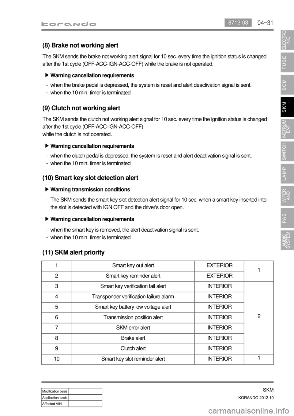
(11) SKM alert priority
1 Smart key out alert EXTERIOR
1
2 Smart key reminder alert EXTERIOR
3 Smart key verification fail alert INTERIOR
2 4 Transponder verification failure alarm INTERIOR
5 Smart key battery low voltage alert INTERIOR
6 Transmission position alert INTERIOR
7 SKM error alert INTERIOR
8 Brake alert INTERIOR
9 Clutch alert INTERIOR
10 Smart key slot reminder alert INTERIOR1
Warning cancellation requirements ▶
Warning cancellation requirements ▶
Warning transmission conditions ▶
Warning cancellation requirements ▶
when the smart key is removed, the alert deactivation signal is sent.
when the 10 min. timer is terminated -
-
Page 709 of 1082
05-46
Pin No.Message
Operating condition
Domestic Export
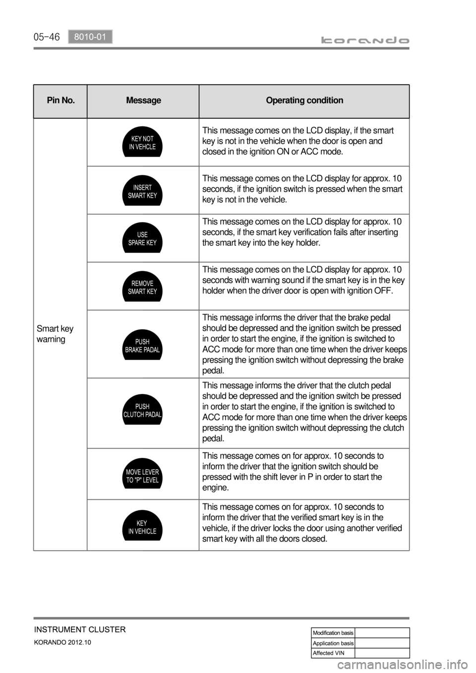
Smart key
warningThis message comes on the LCD display, if the smart
key is not in the vehicle when the door is open and
closed in the ignition ON or ACC mode.
This message comes on the LCD display for approx. 10
seconds, if the ignition switch is pressed when the smart
key is not in the vehicle.
This message comes on the LCD display for approx. 10
seconds, if the smart key verification fails after inserting
the smart key into the key holder.
This message comes on the LCD display for approx. 10
seconds with warning sound if the smart key is in the key
holder when the driver door is open with ignition OFF.
This message informs the driver that the brake pedal
should be depressed and the ignition switch be pressed
in order to start the engine, if the ignition is switched to
ACC mode for more than one time when the driver keeps
pressing the ignition switch without depressing the brake
pedal.
This message informs the driver that the clutch pedal
should be depressed and the ignition switch be pressed
in order to start the engine, if the ignition is switched to
ACC mode for more than one time when the driver keeps
pressing the ignition switch without depressing the clutch
pedal.
This message comes on for approx. 10 seconds to
inform the driver that the ignition switch should be
pressed with the shift lever in P in order to start the
engine.
This message comes on for approx. 10 seconds to
inform the driver that the verified smart key is in the
vehicle, if the driver locks the door using another verified
smart key with all the doors closed.
Pin No. Message Operating condition
Page 820 of 1082
01-10
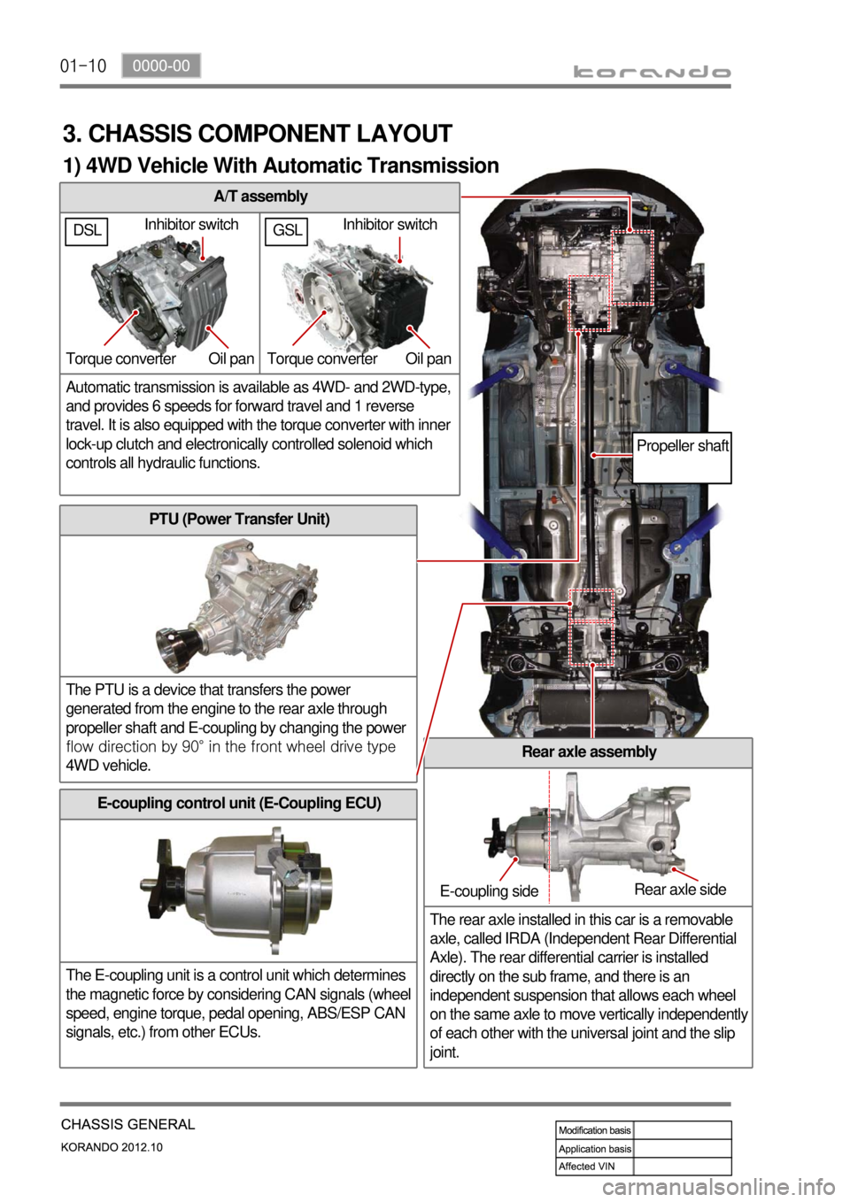
A/T assembly
Automatic transmission is available as 4WD- and 2WD-type,
and provides 6 speeds for forward travel and 1 reverse
travel. It is also equipped with the torque converter with inner
lock-up clutch and electronically controlled solenoid which
controls all hydraulic functions.
3. CHASSIS COMPONENT LAYOUT
PTU (Power Transfer Unit)
The PTU is a device that transfers the power
generated from the engine to the rear axle through
propeller shaft and E-coupling by changing the power
<008d00930096009e0047008b00900099008c008a009b0090009600950047008900a000470060005700b60047009000950047009b008f008c0047008d009900960095009b0047009e008f008c008c00930047008b00990090009d008c0047009b00a0009700
8c0047>
4WD vehicle.
Rear axle assembly
The rear axle installed in this car is a removable
axle, called IRDA (Independent Rear Differential
Axle). The rear differential carrier is installed
directly on the sub frame, and there is an
independent suspension that allows each wheel
on the same axle to move vertically independentl
y
of each other with the universal joint and the slip
joint.
E-coupling control unit (E-Coupling ECU)
The E-coupling unit is a control unit which determines
the magnetic force by considering CAN signals (wheel
speed, engine torque, pedal opening, ABS/ESP CAN
signals, etc.) from other ECUs.
Inhibitor switch
Torque converter Oil pan
E-coupling sideRear axle side
Propeller shaft
1) 4WD Vehicle With Automatic Transmission
GSLDSLInhibitor switch
Torque converter Oil pan
Page 821 of 1082
01-110000-00
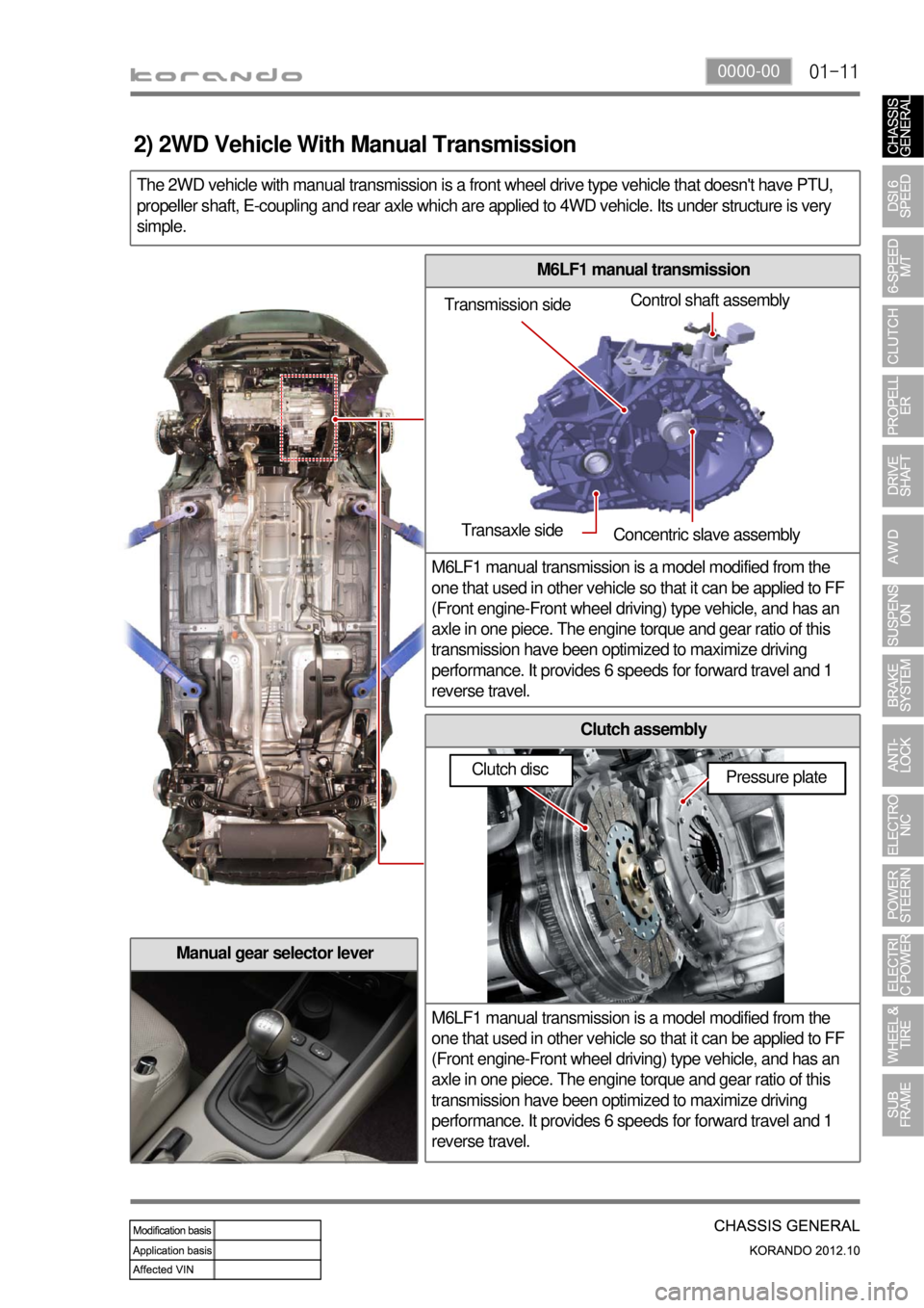
M6LF1 manual transmission
M6LF1 manual transmission is a model modified from the
one that used in other vehicle so that it can be applied to FF
(Front engine-Front wheel driving) type vehicle, and has an
axle in one piece. The engine torque and gear ratio of this
transmission have been optimized to maximize driving
performance. It provides 6 speeds for forward travel and 1
reverse travel.
Clutch assembly
M6LF1 manual transmission is a model modified from the
one that used in other vehicle so that it can be applied to FF
(Front engine-Front wheel driving) type vehicle, and has an
axle in one piece. The engine torque and gear ratio of this
transmission have been optimized to maximize driving
performance. It provides 6 speeds for forward travel and 1
reverse travel.
The 2WD vehicle with manual transmission is a front wheel drive type vehicle that doesn't have PTU,
propeller shaft, E-coupling and rear axle which are applied to 4WD vehicle. Its under structure is very
simple.
Manual gear selector lever
Transmission sideControl shaft assembly
Transaxle side
Concentric slave assembly
Pressure plate
2) 2WD Vehicle With Manual Transmission
Clutch disc
Page 837 of 1082
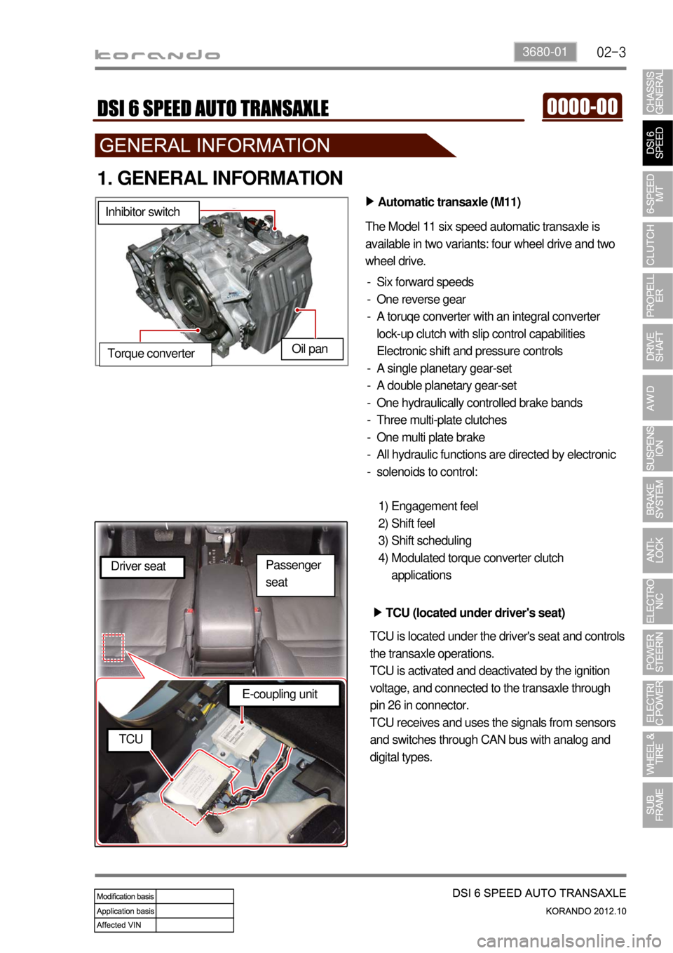
02-33680-01
1. GENERAL INFORMATION
Automatic transaxle (M11) ▶
The Model 11 six speed automatic transaxle is
available in two variants: four wheel drive and two
wheel drive.
Six forward speeds
One reverse gear
A toruqe converter with an integral converter
lock-up clutch with slip control capabilities
Electronic shift and pressure controls
A single planetary gear-set
A double planetary gear-set
One hydraulically controlled brake bands
Three multi-plate clutches
One multi plate brake
All hydraulic functions are directed by electronic
solenoids to control: -
-
-
-
-
-
-
-
-
-
Engagement feel
Shift feel
Shift scheduling
Modulated torque converter clutch
applications 1)
2)
3)
4) Inhibitor switch
Oil pan
Torque converter
TCU (located under driver's seat) ▶
TCU is located under the driver's seat and controls
the transaxle operations.
TCU is activated and deactivated by the ignition
voltage, and connected to the transaxle through
pin 26 in connector.
TCU receives and uses the signals from sensors
and switches through CAN bus with analog and
digital types. Driver seat
E-coupling unit
TCU
Passenger
seat
Page 840 of 1082

02-6
2) Sectional Diagram
Double planetary gear-set
Clutch packSingle planetary gear-set
Oil pump
Torque converter
Input shaft
Intermediate shaft
Differential assembly
Page 842 of 1082
02-8
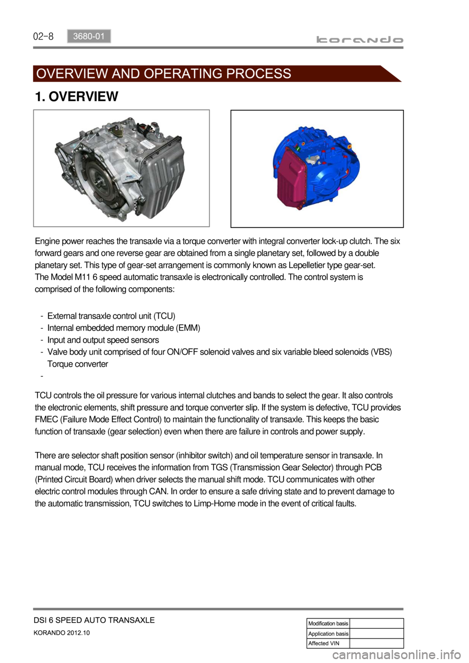
1. OVERVIEW
Engine power reaches the transaxle via a torque converter with integral converter lock-up clutch. The six
forward gears and one reverse gear are obtained from a single planetary set, followed by a double
planetary set. This type of gear-set arrangement is commonly known as Lepelletier type gear-set.
The Model M11 6 speed automatic transaxle is electronically controlled. The control system is
comprised of the following components:
External transaxle control unit (TCU)
Internal embedded memory module (EMM)
Input and output speed sensors
Valve body unit comprised of four ON/OFF solenoid valves and six variable bleed solenoids (VBS)
Torque converter -
-
-
-
-
TCU controls the oil pressure for various internal clutches and bands to select the gear. It also controls
the electronic elements, shift pressure and torque converter slip. If the system is defective, TCU provides
FMEC (Failure Mode Effect Control) to maintain the functionality of transaxle. This keeps the basic
function of transaxle (gear selection) even when there are failure in controls and power supply.
There are selector shaft position sensor (inhibitor switch) and oil temperature sensor in transaxle. In
manual mode, TCU receives the information from TGS (Transmission Gear Selector) through PCB
(Printed Circuit Board) when driver selects the manual shift mode. TCU communicates with other
electric control modules through CAN. In order to ensure a safe driving state and to prevent damage to
the automatic transmission, TCU switches to Limp-Home mode in the event of critical faults.
Page 843 of 1082
02-93680-01
2. FEATURES
1) Advantages
Early Downshift with Hard Braking and Skip Shifts ▶
When heavy braking is detected, the transaxle downshifts early and skips gears to provide increased
engine braking to provide gear selection for tip-in.
Gear Hold going Uphill/Downhill ▶
If the accelerator pedal is released when traveling uphill, upshifts are prevented to reduce busyness on
grades. If the accelerator pedal is released when traveling downhill, upshifts are prevented to enhance
engine braking.
Drive and Reverse Engagement ▶
A soft engagement feature avoids harsh take up of drive when selecting Drive or Reverse. This is
achieved by limiting engine speed and engine torque which results in a rapid, but progressive
engagement of either Drive or Reverse when moving from the Park or Neutral positions. Drive and
Reverse engagements from either Park or Neutral are performed in less than 2.2 seconds. There is no
drive engagement prevention strategy implemented on the transaxle system as there is sufficient engine
strategy to protect the system. However, reverse engagement is prevented until engine speed is less
than 1,400 rpm and the accelerator pedal position is less than 12% and vehicle speed is less than 10
km/h.
Converter Clutch Lock-Up In All Gears ▶
The transaxle features converter clutch lock-up in all gears. This feature provides improved fuel economy
and vehicle performance. It also improves transaxle cooling efficiency when towing heavy loads at low
speeds, e.g. in city driving or hill terrain.
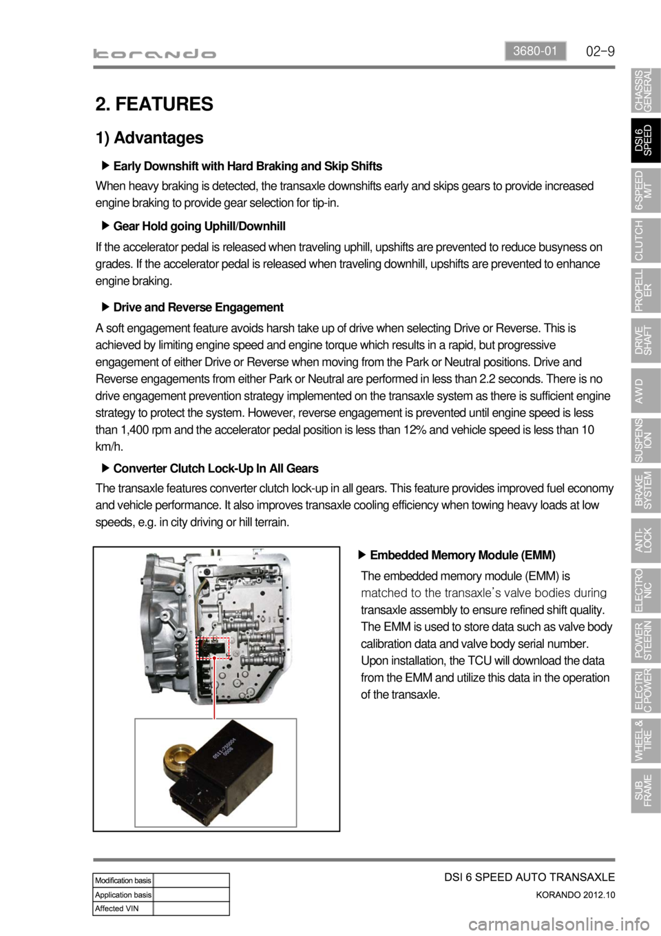
Embedded Memory Module (EMM) ▶
The embedded memory module (EMM) is
matched to the transaxle’s valve bodies during
transaxle assembly to ensure refined shift quality.
The EMM is used to store data such as valve body
calibration data and valve body serial number.
Upon installation, the TCU will download the data
from the EMM and utilize this data in the operation
of the transaxle.
Page 844 of 1082

02-10
2) Transaxle Cooling
The transaxle cooling system ensures rapid warm-up and constant operating temperature resulting in
reduced fuel consumption and refined shift quality.
It also includes a cooler by-pass within the hydraulic system to allow sufficient lubrication to the transaxle
drivetrain in the event of a blockage in the transaxle cooler.
3) Shift Strategy
Gear Change ▶
Transaxle gear change is controlled by the
TCU. The TCU receives inputs from various
engine and vehicle sensors to select shift
schedules and to control the shift feel and
torque converter clutch (TCC) operation at each
gear change.
Coast down ▶
Coast down down shifts occur at 0% pedal
when the vehicle is coasting down to a stop.
Torque Demand ▶
Torque demand down shifts occur
(automatically) when the driver demand for
torque is greater than the engine can provide at
that gear ratio. If applied, the transaxle will
disengage the TCC to provide added
acceleration.
Page 847 of 1082
02-133680-01
4. LIMP HOME MODE
When the transaxle is defective ▶
In the event of a system fault, the TCU also provides for failure mode effect control (FMEC) to maintain
maximum functional operation of the transaxle.
In the event of a total loss of control or electrical power, the basic transaxle functions (Park, Reverse,
Neutral and Drive) are retained. The 4th and reverse gear ratios with the torque converter clutch in the
unlocked state are the retained gear states the hydraulic system supports without any electrical
assistance.
The TCU communicates with other vehicle electronic control modules by the controller area network
(CAN). If a major fault develops, the transaxle may automatically operate in a "limp home" (failure)
mode to enable the vehicle to be driven to an authorized dealer for repair.
The TCU also provides for transaxle diagnostics, which meet the requirements of OBD II legislation,
monitoring all components which may effect vehicle emissions. 1.
2.
3.
4.
When the transaxle overheats ▶
Limp home mode may also be engaged if the battery charge falls below 8V.
If the transaxle overheats, the shift patterns will automatically change to enable improved transaxle
cooling.
During transaxle overheat, the instrument cluster transaxle selector position display and the over
<009b008c00940097008c00990088009b009c0099008c0047008a00960095008b0090009b00900096009500470090009a004700900095008b0090008a0088009b008c008b0047008900a00047008d00930088009a008f00900095008e0047009b008f008c00
4702c8007e004f007e00900095009b008c0099005002c90047>indicator on the instrument
cluster until normal transaxle operating temperature is reached. 1.
2.
3.
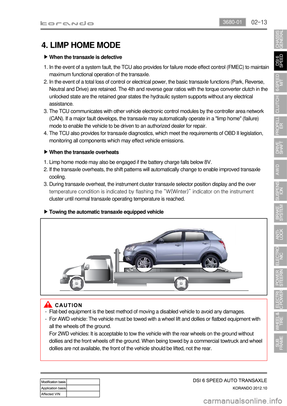
Towing the automatic transaxle equipped vehicle ▶
Flat-bed equipment is the best method of moving a disabled vehicle to avoid any damages.
For AWD vehicle: The vehicle must be towed with a wheel lift and dollies or flatbed equipment with
all the wheels off the ground.
For 2WD vehicles: It is acceptable to tow the vehicle with the rear wheels on the ground without
dollies and the front wheels off the ground. When being towed by a commercial towtruck and wheel
dollies are not available, the front of the vehicle should be lifted, not the rear. -
-