ECU SSANGYONG KORANDO 2012 Owner's Guide
[x] Cancel search | Manufacturer: SSANGYONG, Model Year: 2012, Model line: KORANDO, Model: SSANGYONG KORANDO 2012Pages: 1082, PDF Size: 96.1 MB
Page 286 of 1082
15-10
(2) Fuel Control
a. Fuel Pressure Control Elements
Pressure control consists of 2 principles.
Determines rail pressure according to engine operating conditions.
Controls IMV to make the rail pressure to reach to the required value. -
-
Pressure in the fuel rail is determined according to engine speed and load on the engine.
When engine speed and load are high
The degree of turbulence is very great and the fuel can be injected at very high pressure in order to
optimize combustion.
When engine speed and load are low
The degree of turbulence is low. If injection pressure is too high, the nozzle's penetration will be
excessive and part of the fuel will be sprayed directly onto the sides of the cylinder, causing
incomplete combustion. So there occurs smoke and damages engine durability. -
-
Fuel pressure is corrected according to air temperature, coolant temperature and atmospheric pressure
and to take account of the added ignition time caused by cold running or by high altitude driving. A
special pressure demand is necessary in order to obtain the additional flow required during starts. This
demand is determined according to injected fuel and coolant temperature.
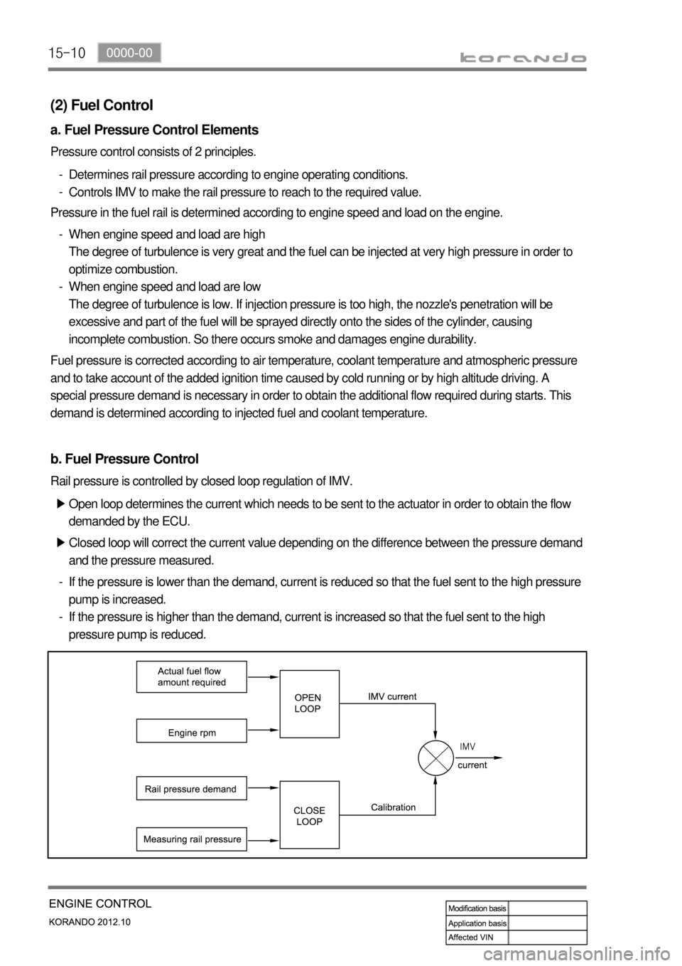
b. Fuel Pressure Control
Open loop determines the current which needs to be sent to the actuator in order to obtain the flow
demanded by the ECU. ▶
Closed loop will correct the current value depending on the difference between the pressure demand
and the pressure measured. ▶
If the pressure is lower than the demand, current is reduced so that the fuel sent to the high pressure
pump is increased.
If the pressure is higher than the demand, current is increased so that the fuel sent to the high
pressure pump is reduced. -
-
Rail pressure is controlled by closed loop regulation of IMV.
Page 294 of 1082
15-18
This is done periodically under certain operating conditions. When the resetting is finished, the new
minimum pulse value replaces the value obtained during the previous resetting. The first MDP value is
provided by the C3I. Each resetting then allows the closed loop of the MDP to be updated according to
the deviation of the injector.
b. Detection of leaks in the cylinders
The accelerometer is also used to detect any injector which may have stuck open. The detection
principle is based on monitoring the ratio. If there is a leak in the cylinder, the accumulated fuel self-
ignites as soon as the temperature and pressure conditions are favorable (high engine speed, high load
and small leak).
This combustion is set off at about 20 degrees before TDC and before main injection.
The ratio therefore increases considerably in the detection window. It is this increase which allows the
leaks to be detected. The threshold beyond which a fault is signaled is a percentage of the maximum
possible value of the ratio.
Because of the severity of the recovery process (engine shut-down), the etection must be extremely
robust.
An increase in the ratio can be the consequence of various causes:
Pilot injection too much
Main combustion offset
Fuel leak in the cylinder -
-
-
If the ratio becomes too high, the strategy initially restricts the pilot injection flow and retards the main
injection. If the ratio remains high despite these interventions, this shows that a real leak is present, a
fault is signaled and the engine is shut down.
c. Detection of an accelerometer fault
This strategy permits the detection of a fault in the sensor or in the wiring loom connecting the sensor to
the ECU.
It is based on detection of the combustion. When the engine is idling, the detection window is set too low
for the combustion caused by the main injection. If the ratio increases, this shows that the accelerometer
is working properly, but otherwise a fault is signaled to indicate a sensor failure. The recovery modes
associated with this fault consist of inhibition of the pilot injection and discharge through the injectors.
Page 295 of 1082
15-190000-00
HFM
Accelerator pedalCoolant
temperature
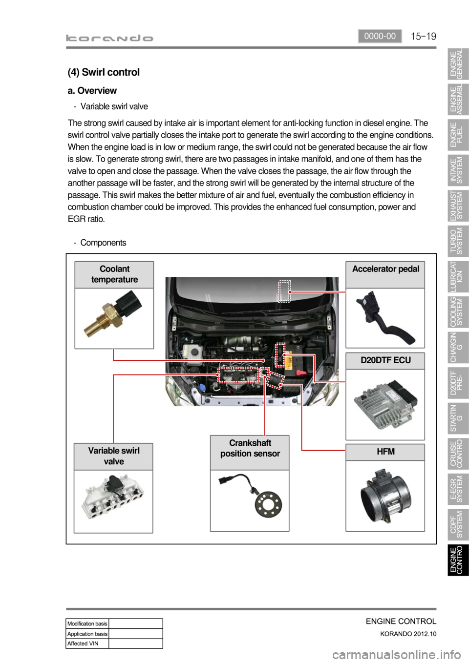
(4) Swirl control
a. Overview
Variable swirl valve -
The strong swirl caused by intake air is important element for anti-locking function in diesel engine. The
swirl control valve partially closes the intake port to generate the swirl according to the engine conditions.
When the engine load is in low or medium range, the swirl could not be generated because the air flow
is slow. To generate strong swirl, there are two passages in intake manifold, and one of them has the
valve to open and close the passage. When the valve closes the passage, the air flow through the
another passage will be faster, and the strong swirl will be generated by the internal structure of the
passage. This swirl makes the better mixture of air and fuel, eventually the combustion efficiency in
combustion chamber could be improved. This provides the enhanced fuel consumption, power and
EGR ratio.
Components -
D20DTF ECU
Crankshaft
position sensor
Variable swirl
valve
Page 300 of 1082

15-24
HFM sensor
(intake air temp.)
Oxygen sensorD20DTF ECU
T-MAP sensor
(5) EGR control
a. Overview
The EGR (Electric-Exhaust Gas Recirculation) valve reduces the NOx emission level by recirculating
some of the exhaust gas to the intake system.
The major difference with the previous EURO 4 type, is that the DC motor with improved response rate
according to the EURO 5 regulation. The solenoid type actuator is used in the conventional model, but in
this new model, the DC motor type actuator with improved response rate is adopted. Also the hall senso
r
which provides a more stabilized signal than the potentiometer, and the EGR bypass flap which
improves engine warming up efficiency are also used. The HFM sensor and the position sensor are
used to feedback the amount of EGR for both EURO 4 and EURO 5.
b. Components
Electronic
throttle body
Coolant
temp.sensor
E-EGR valveCrankshaft posi.
sensor
Accelerator
pedalE-EGR cooler
Page 302 of 1082
15-26
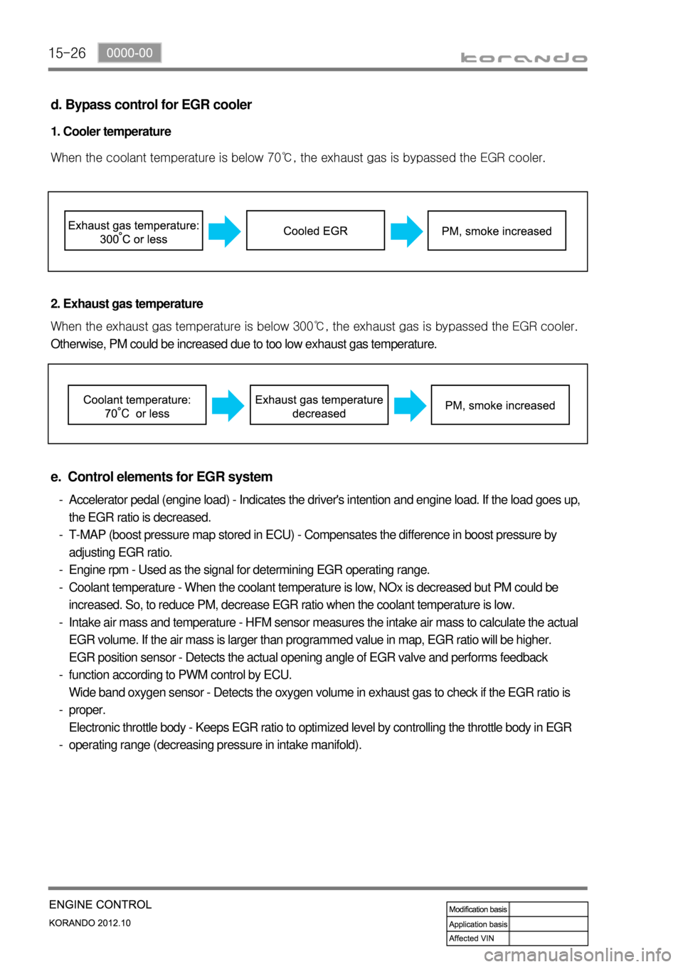
d. Bypass control for EGR cooler
1. Cooler temperature
<007e008f008c00950047009b008f008c0047008a00960096009300880095009b0047009b008c00940097008c00990088009b009c0099008c00470090009a00470089008c00930096009e0047005e00570b4500530047009b008f008c0047008c009f008f00
88009c009a009b0047008e0088009a00470090009a00470089>ypassed the EGR cooler.
2. Exhaust gas temperature
<007e008f008c00950047009b008f008c0047008c009f008f0088009c009a009b0047008e0088009a0047009b008c00940097008c00990088009b009c0099008c00470090009a00470089008c00930096009e0047005a005700570b4500530047009b008f00
8c0047008c009f008f0088009c009a009b0047008e0088009a> is bypassed the EGR cooler.
Otherwise, PM could be increased due to too low exhaust gas temperature.
e. Control elements for EGR system
Accelerator pedal (engine load) - Indicates the driver's intention and engine load. If the load goes up,
the EGR ratio is decreased.
T-MAP (boost pressure map stored in ECU) - Compensates the difference in boost pressure by
adjusting EGR ratio.
Engine rpm - Used as the signal for determining EGR operating range.
Coolant temperature - When the coolant temperature is low, NOx is decreased but PM could be
increased. So, to reduce PM, decrease EGR ratio when the coolant temperature is low.
Intake air mass and temperature - HFM sensor measures the intake air mass to calculate the actual
EGR volume. If the air mass is larger than programmed value in map, EGR ratio will be higher.
EGR position sensor - Detects the actual opening angle of EGR valve and performs feedback
function according to PWM control by ECU.
Wide band oxygen sensor - Detects the oxygen volume in exhaust gas to check if the EGR ratio is
proper.
Electronic throttle body - Keeps EGR ratio to optimized level by controlling the throttle body in EGR
operating range (decreasing pressure in intake manifold). -
-
-
-
-
-
-
-
Page 304 of 1082
15-28
Accelerator
pedal
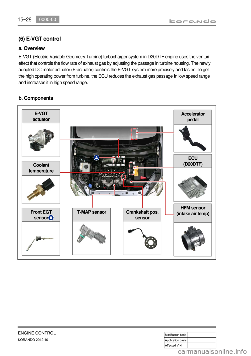
(6) E-VGT control
a. Overview
E-VGT (Electric-Variable Geometry Turbine) turbocharger system in D20DTF engine uses the venturi
effect that controls the flow rate of exhaust gas by adjusting the passage in turbine housing. The newly
adopted DC motor actuator (E-actuator) controls the E-VGT system more precisely and faster. To get
the high operating power from turbine, the ECU reduces the exhaust gas passage In low speed range
and increases it in high speed range.
b. Components
E-VGT
actuator
Coolant
temperature
Front EGT
sensorT-MAP sensorCrankshaft pos,
sensor
HFM sensor
(intake air temp)
ECU
(D20DTF)
Page 306 of 1082
15-30
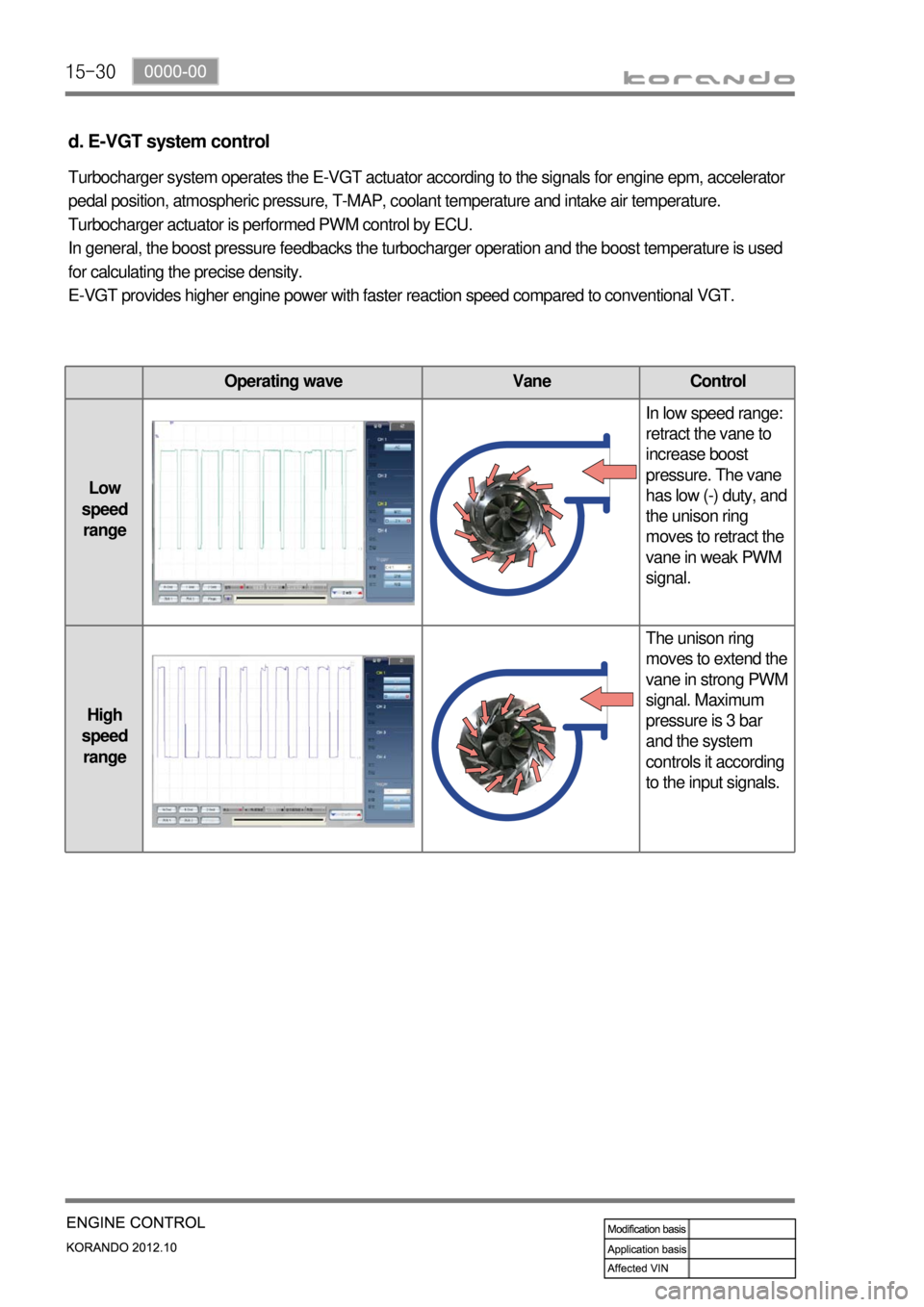
d. E-VGT system control
Turbocharger system operates the E-VGT actuator according to the signals for engine epm, accelerator
pedal position, atmospheric pressure, T-MAP, coolant temperature and intake air temperature.
Turbocharger actuator is performed PWM control by ECU.
In general, the boost pressure feedbacks the turbocharger operation and the boost temperature is used
for calculating the precise density.
E-VGT provides higher engine power with faster reaction speed compared to conventional VGT.
Operating wave Vane Control
Low
speed
rangeIn low speed range:
retract the vane to
increase boost
pressure. The vane
has low (-) duty, and
the unison ring
moves to retract the
vane in weak PWM
signal.
High
speed
rangeThe unison ring
moves to extend the
vane in strong PWM
signal. Maximum
pressure is 3 bar
and the system
controls it according
to the input signals.
Page 307 of 1082

15-310000-00
HFM sensor
(air mass)
CDPF
(7) Wide band oxygen sensor
a. Overview
For diesel engine, combustion is not performed at the optimum (theoretically correct) air-fuel ratio and
the oxygen concentration is thin in most cases. So the wide-band oxygen sensor is used for this kind of
engine, and this sensor is a little different from the one that used for gasoline engine. The combustion in
diesel engine is controlled by fuel injection volume. Therefore, the wide band oxygen sensor should be
used in diesel engine. This sensor measures the air-fuel ratio in very wide range, and is also called full
range oxygen sensor.
The wide band oxygen sensor measures the oxygen density in exhaust gas and sends it to ECU to
control the EGR more precisely. -
b. Components
D20DTF
ECU
EGR valveElectronic
throttle bodyCoolant temp.
sensor
Oxygen
sensorInjector (C3I)
Page 310 of 1082
15-34
Coolant temp.
sensor
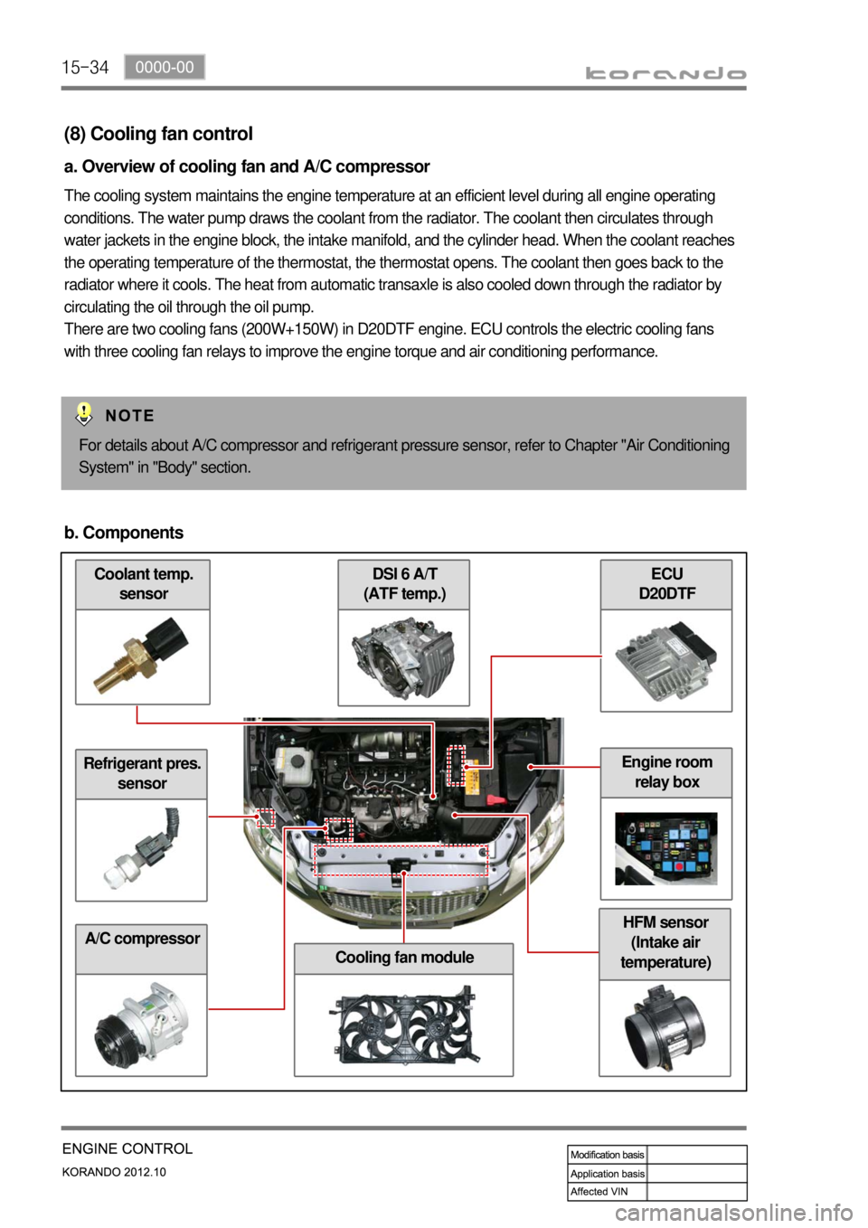
(8) Cooling fan control
a. Overview of cooling fan and A/C compressor
The cooling system maintains the engine temperature at an efficient level during all engine operating
conditions. The water pump draws the coolant from the radiator. The coolant then circulates through
water jackets in the engine block, the intake manifold, and the cylinder head. When the coolant reaches
the operating temperature of the thermostat, the thermostat opens. The coolant then goes back to the
radiator where it cools. The heat from automatic transaxle is also cooled down through the radiator by
circulating the oil through the oil pump.
There are two cooling fans (200W+150W) in D20DTF engine. ECU controls the electric cooling fans
with three cooling fan relays to improve the engine torque and air conditioning performance.
For details about A/C compressor and refrigerant pressure sensor, refer to Chapter "Air Conditioning
System" in "Body" section.
b. Components
Refrigerant pres.
sensor
A/C compressor
ECU
D20DTF DSI 6 A/T
(ATF temp.)
Cooling fan module
HFM sensor
(Intake air
temperature)
Engine room
relay box
Page 313 of 1082
15-370000-00
HFM
(Intake air temp.)Coolant temp.
sensor
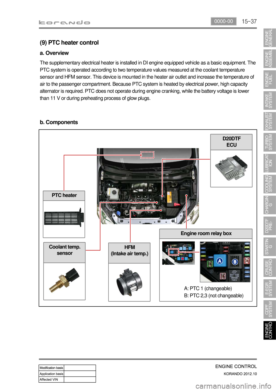
(9) PTC heater control
a. Overview
The supplementary electrical heater is installed in DI engine equipped vehicle as a basic equipment. The
PTC system is operated according to two temperature values measured at the coolant temperature
sensor and HFM sensor. This device is mounted in the heater air outlet and increase the temperature of
air to the passenger compartment. Because PTC system is heated by electrical power, high capacity
alternator is required. PTC does not operate during engine cranking, while the battery voltage is lower
than 11 V or during preheating process of glow plugs.
b. Components
PTC heater
D20DTF
ECU
Engine room relay box
A: PTC 1 (changeable)
B: PTC 2,3 (not changeable)