automatic SSANGYONG KORANDO 2012 Manual Online
[x] Cancel search | Manufacturer: SSANGYONG, Model Year: 2012, Model line: KORANDO, Model: SSANGYONG KORANDO 2012Pages: 1082, PDF Size: 96.1 MB
Page 869 of 1082

03-93660-01
DescriptionsSize x
NumbersTightening torque
(Nm)
Automatic
transaxleBolt (oil lubrication pipe) 10 mm X 1 9.8 ~ 11.7Nm
Bolt (oil pump) 12 mm X 7 20.0 ~ 26.0Nm
Bolt (parking rod guide) 10 mm X 2 9.8 ~ 11.7Nm
Bolt (U/D brake retainer) T40 X 6 31.0 ~ 36.0Nm
Bolt (U/D brake chamber) T30 X 2 4.9 ~ 9.8Nm
Bolt (rear cover) 12 mm X 13 28.0 ~ 35.0Nm
Page 871 of 1082

03-113660-01
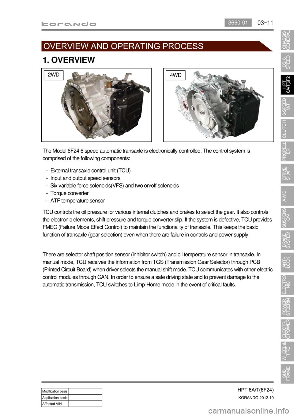
1. OVERVIEW
2WD4WD
The Model 6F24 6 speed automatic transaxle is electronically controlled. The control system is
comprised of the following components:
External transaxle control unit (TCU)
Input and output speed sensors
Six variable force solenoids(VFS) and two on/off solenoids
Torque converter
ATF temperature sensor -
-
-
-
-
TCU controls the oil pressure for various internal clutches and brakes to select the gear. It also controls
the electronic elements, shift pressure and torque converter slip. If the system is defective, TCU provides
FMEC (Failure Mode Effect Control) to maintain the functionality of transaxle. This keeps the basic
function of transaxle (gear selection) even when there are failure in controls and power supply.
There are selector shaft position sensor (inhibitor switch) and oil temperature sensor in transaxle. In
manual mode, TCU receives the information from TGS (Transmission Gear Selector) through PCB
(Printed Circuit Board) when driver selects the manual shift mode. TCU communicates with other electric
control modules through CAN. In order to ensure a safe driving state and to prevent damage to the
automatic transmission, TCU switches to Limp-Home mode in the event of critical faults.
Page 873 of 1082

03-133660-01
2) Transaxle Cooling
The transaxle cooling system ensures rapid warm-up and constant operating temperature resulting in
reduced fuel consumption and refined shift quality.
It also includes a cooler by-pass within the hydraulic system to allow sufficient lubrication to the transaxle
drivetrain in the event of a blockage in the transaxle cooler.
3) Shift Strategy
Gear Change ▶
Transaxle gear change is controlled by the
TCU. The TCU receives inputs from various
engine and vehicle sensors to select shift
schedules and to control the shift feel and
torque converter clutch (TCC) operation at each
gear change.
Coast down ▶
Coast down down shifts occur at 0% pedal
when the vehicle is coasting down to a stop.
Torque Demand ▶
Torque demand down shifts occur
(automatically) when the driver demand for
torque is greater than the engine can provide at
that gear ratio. If applied, the transaxle will
disengage the TCC to provide added
acceleration.
Page 876 of 1082

03-16
4. LIMP HOME MODE
When the transaxle is defective ▶
In the event of a system fault, the TCU also provides for failure mode effect control (FMEC) to maintain
maximum functional operation of the transaxle. (There are 3 FMEC modes, mechanical limp-home
mode, electrical limp-home mode, limp-home mode C.)
In the event of a total loss of control or electrical power, the basic transaxle functions (Park, Reverse,
Neutral and Drive) are retained. The 4th and reverse gear ratios with the torque converter clutch in the
unlocked state are the retained gear states the hydraulic system supports without any electrical
assistance. (Mechanical limp-home)
If the speed sensor circuit is failed, the gear is fixed to 4th gear, but manual shifting
<004f00590095008b02e9005a0099008b02e9005b009b008f005000470090009a00470088009d008800900093008800890093008c0055004f006c0093008c008a009b00990090008a00880093004700930090009400970047008f00960094008c0047009400
96008b008c0050>
If the inhibitor switch signals are invalid, shifting to1st and 2nd gear is forbidden. (Limp-home C)
The TCU communicates with other vehicle electronic control modules by the controller area network
(CAN). If a major fault is developed, the transaxle may not accomplish the intelligent shift control. The
TCU controls the transaxle with preset values.
The TCU also provides for transaxle diagnostics, which meet the requirements of OBD II regulation,
monitoring all components which may effect vehicle emissions. 1.
2.
3.
4.
5.
6.
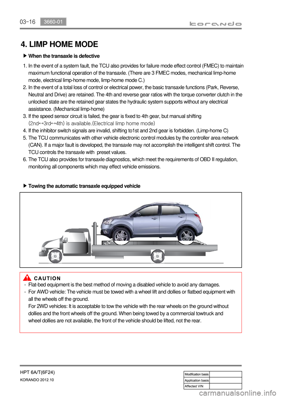
Towing the automatic transaxle equipped vehicle ▶
Flat-bed equipment is the best method of moving a disabled vehicle to avoid any damages.
For AWD vehicle: The vehicle must be towed with a wheel lift and dollies or flatbed equipment with
all the wheels off the ground.
For 2WD vehicles: It is acceptable to tow the vehicle with the rear wheels on the ground without
dollies and the front wheels off the ground. When being towed by a commercial towtruck and
wheel dollies are not available, the front of the vehicle should be lifted, not the rear. -
-
Page 914 of 1082

07-4
1. OVERVIEW
The AWD system in this vehicle is the electronic 4WD system and controls the traction to rear wheels
according to the driving conditions.
1) Driving Mode
(1) AUTO mode (Normal driving mode)
Normally the vehicle is in 2WD mode.
Automatically change to this mode when the vehicle needs higher traction.
(2) LOCK mode (when pressing 4WD LOCK switch)
This mode provides the highest traction. Use
this mode when driving on unpaved, rugged,
steep, sandy, wet or slippery roads.
In 4WD LOCK mode, if the rear wheel speed
exceeds 40 km/h, 4WD LOCK mode is
canceled and 4WD AUTO mode is activated
(Indicator OFF). If the speed is decreased
below 35 km/h, 4WD LOCK mode is resumed
(Indicator ON again). -
-
Mode table ▶
4WD LOCK switch Vehicle speed Driving mode
Not pressed (4WD AUTO) No conditions 4WD AUTO
Pressed (4WD LOCK) over 40 km/h 4WD AUTO
Pressed (4WD LOCK) below 35 km/h 4WD LOCK
Page 923 of 1082

09-34850-00
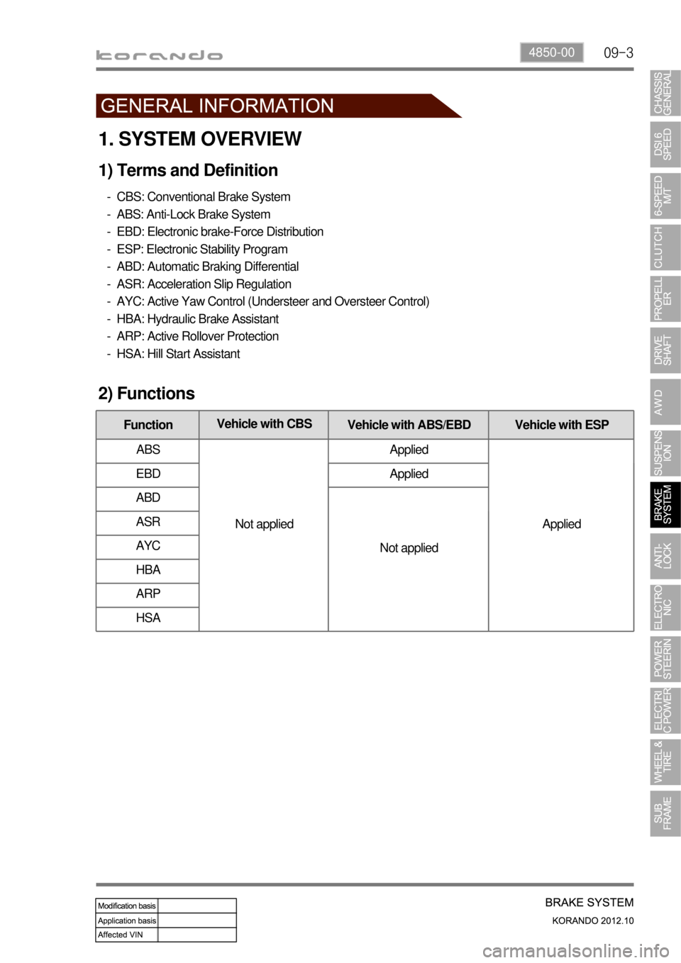
1. SYSTEM OVERVIEW
1) Terms and Definition
CBS: Conventional Brake System
ABS: Anti-Lock Brake System
EBD: Electronic brake-Force Distribution
ESP: Electronic Stability Program
ABD: Automatic Braking Differential
ASR: Acceleration Slip Regulation
AYC: Active Yaw Control (Understeer and Oversteer Control)
HBA: Hydraulic Brake Assistant
ARP: Active Rollover Protection
HSA: Hill Start Assistant -
-
-
-
-
-
-
-
-
-
2) Functions
FunctionVehicle with CBS
Vehicle with ABS/EBD Vehicle with ESP
ABS
Not appliedApplied
Applied EBD Applied
ABD
Not applied ASR
AYC
HBA
ARP
HSA
Page 936 of 1082

10-54890-00
1. SYSTEM OVERVIEW
1) What is ABS?
When braking suddenly or braking on slippery roads, the vehicle keeps moving forward but the wheels
are locking and not rotating. If these happen, the vehicle may lose stability or rotate resulting in an
accident. ABS helps to maintain directional stability and control of the vehicle. ABS is designed to
secure more safety and increase the control of steering wheel during emergency braking situation. But,
ABS does not guarantee perfect safety beyond its physical limit. ABS in this vehicle contains EBD
function. In normal driving conditions, the brake system operates without ABS function.
2) What is EBD (Electronic Brake-force Distribution)?
EBD is an automobile brake technology that automatically varies the amount of force applied to each of a
vehicle's brakes, based on road conditions, speed, loading, etc. Always coupled with anti-lock braking
systems, EBD can apply more or less braking pressure to each wheel in order to maximize stopping
power whilst maintaining vehicular control. EBD does not operate when ABS is working.ABS effect according to braking conditions ▶
Braking on split road Maneuvering while braking
Page 958 of 1082

11-6
1. OVERVIEW
The ESP (Electronic Stability Program) has been developed to help a driver avoid danger of losing
control of the vehicle stability due to understeer or oversteer during cornering. The yaw rate sensor,
lateral sensor and longitudinal sensor in the sensor cluster and the steering wheel angle sensor under
the steering column detect the vehicle conditions when the inner or outer wheels are spinning during
oversteer, understeer or cornering. The ESP ECU controls against oversteer or understeer during
cornering by controlling the vehicle stability using input values from these sensors and applying the
braking force to the corresponding wheels independently. The system also controls the engine power
right before the wheel spin synchronized to decelerate the vehicle automatically in order to maintain the
vehicle stable during cornering.
Page 964 of 1082

11-12
2) Operation of ESP System
The ESP (Electronic Stability Program) has been developed to help a driver avoid danger of losing
control of the vehicle stability due to understeer or oversteer during cornering. The yaw rate sensor,
lateral sensor and longitudinal sensor in the sensor cluster and the steering wheel angle sensor under
the steering column detect the vehicle conditions when the inner or outer wheels are spinning during
oversteer, understeer or cornering. The ESP ECU controls against oversteer or understeer during
cornering by controlling the vehicle stability using input values from these sensors and applying the
braking force to the corresponding wheels independently. The system also controls the engine power
right before the wheel spin synchronized with the ASR function to decelerate the vehicle automatically in
order to maintain the vehicle stable during cornering.
(1) Under steering
What is understeering? ▶
Understeer is a term for a condition in which the steering wheel is steered to a certain angle during driving
and the front tires slip toward the reverse direction of the desired direction. Generally, vehicles are
designed to have understeer. It is because that the vehicle can return back to inside of cornering line
when the steering wheel is steered toward the inside even when the front wheels are slipped outward.
As the centrifugal force increases, the tires can easily lose the traction and the vehicle tends to slip
outward when the curve angle gets bigger and the speed increases.
Page 971 of 1082

11-190000-00
The BCM flashes the emergency auto hazard flasher with interval of 1.25 times/sec.:
The emergency hazard flasher does not operate if the vehicle speed is over 50 km/h when the
emergency stop signal is received.
The emergency hazard flasher operates if the vehicle speed is 50 km/h or lower when the
emergency stop signal is received.
When vehicle speed increases more than 10 km/h above the speed when the signal is received
during operation by emergency braking signal, the emergency hazard flasher stops operation.
When turning emergency hazard flasher switch OFF during operation by emergency braking signal,
it stops operation.
It is deactivated automatically 10 seconds after if items 2) and 3) above are not met during operation
by emergency braking signal.
If multi-function automatic hazard flasher signal is received during operation by emergency braking
signal, it will be overridden. -
-
-
-
-
-