ECU SSANGYONG KORANDO 2013 Service Manual
[x] Cancel search | Manufacturer: SSANGYONG, Model Year: 2013, Model line: KORANDO, Model: SSANGYONG KORANDO 2013Pages: 1336, PDF Size: 92.18 MB
Page 1131 of 1336

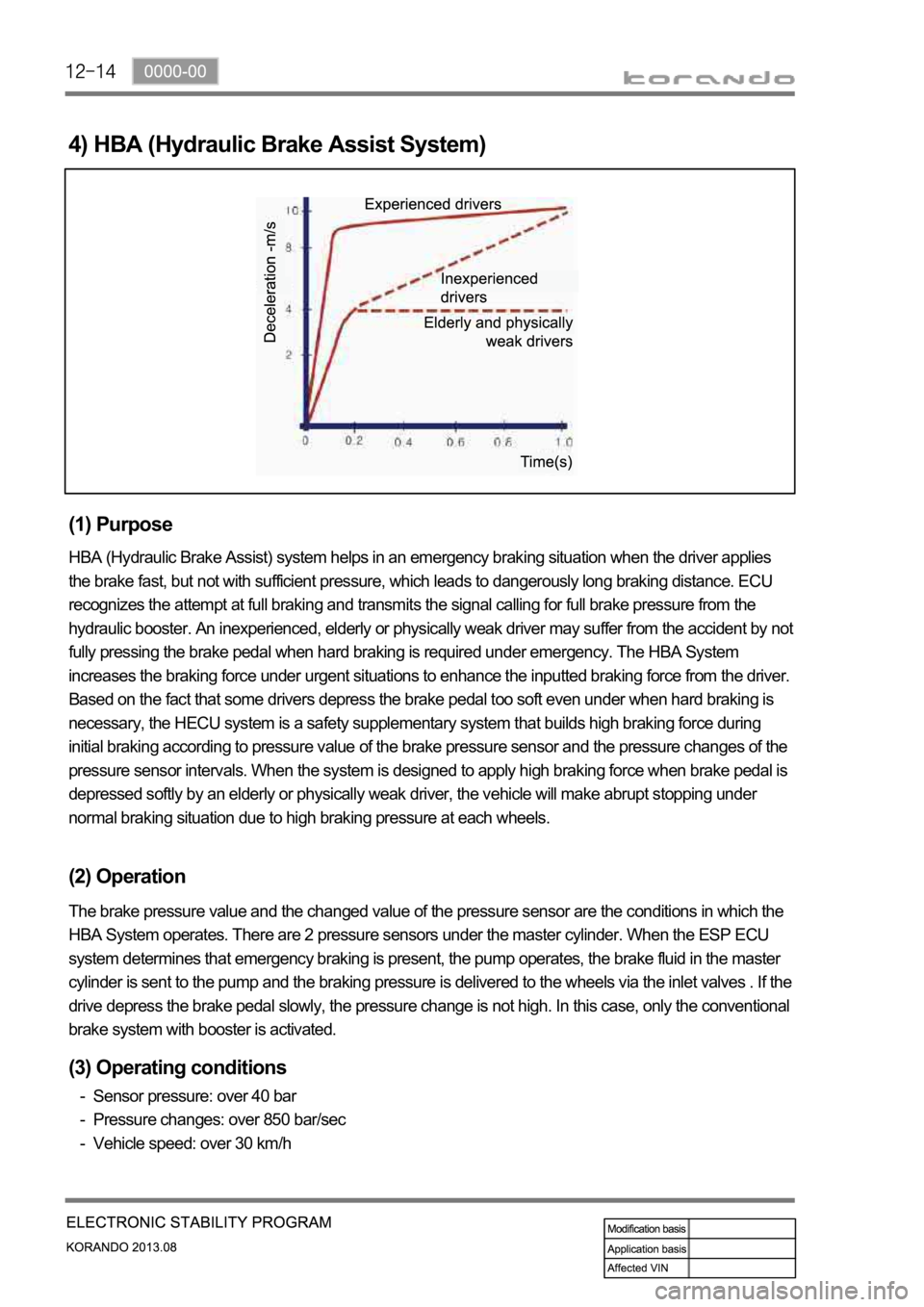
4) HBA (Hydraulic Brake Assist System)
(1) Purpose
HBA (Hydraulic Brake Assist) system helps in an emergency braking situation when the driver applies
the brake fast, but not with sufficient pressure, which leads to dangerously long braking distance. ECU
recognizes the attempt at full braking and transmits the signal calling for full brake pressure from the
hydraulic booster. An inexperienced, elderly or physically weak driver may suffer from the accident by not
fully pressing the brake pedal when hard braking is required under emergency. The HBA System
increases the braking force under urgent situations to enhance the inputted braking force from the driver.
Based on the fact that some drivers depress the brake pedal too soft even under when hard braking is
necessary, the HECU system is a safety supplementary system that builds high braking force during
initial braking according to pressure value of the brake pressure sensor and the pressure changes of the
pressure sensor intervals. When the system is designed to apply high braking force when brake pedal is
depressed softly by an elderly or physically weak driver, the vehicle will make abrupt stopping under
normal braking situation due to high braking pressure at each wheels.
(2) Operation
The brake pressure value and the changed value of the pressure sensor are the conditions in which the
HBA System operates. There are 2 pressure sensors under the master cylinder. When the ESP ECU
system determines that emergency braking is present, the pump operates, the brake fluid in the master
cylinder is sent to the pump and the braking pressure is delivered to the wheels via the inlet valves . If the
drive depress the brake pedal slowly, the pressure change is not high. In this case, only the conventional
brake system with booster is activated.
(3) Operating conditions
Sensor pressure: over 40 bar
Pressure changes: over 850 bar/sec
Vehicle speed: over 30 km/h -
-
-
Page 1133 of 1336

6) HSA (Hill Start Assist)
The HSA (Hill Start Assist) prevents the vehicle from rolling backward by supplying the hydraulic
pressure to the wheels by the HECU after the brake pedal is released when starting off on uphill.
Page 1139 of 1336

2) DUMP (ESP is working) Mode
The pressure decreases just before the wheel speed drops and the wheels are locked.
The inlet valve closes and the outlet valve opens as in the ABS HECU and the oil is gathered at the low
pressure chamber while no additional oil is being supplied. Then the pump operates to allow fast oil
drainage. The shuttle valve and the separation valve do not operate while decompression.
Page 1142 of 1336

0000-00
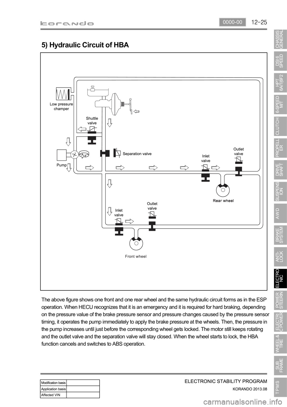
5) Hydraulic Circuit of HBA
The above figure shows one front and one rear wheel and the same hydraulic circuit forms as in the ESP
operation. When HECU recognizes that it is an emergency and it is required for hard braking, depending
on the pressure value of the brake pressure sensor and pressure changes caused by the pressure sensor
timing, it operates the pump immediately to apply the brake pressure at the wheels. Then, the pressure in
the pump increases until just before the corresponding wheel gets locked. The motor still keeps rotating
and the outlet valve and the separation valve will stay closed. When the wheel starts to lock, the HBA
function cancels and switches to ABS operation.
Page 1150 of 1336

4610-00
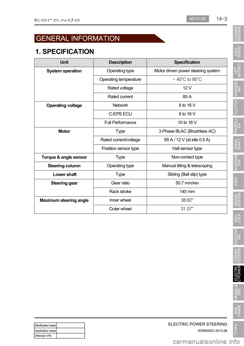
1. SPECIFICATION
Unit Description Specification
System operationOperating type Motor driven power steering system
Operating temperature
Rated voltage 12 V
Rated current 85 A
Operating voltageNetwork 8 to 16 V
C-EPS ECU 8 to 16 V
Full Performance 10 to 16 V
MotorType 3-Phase BLAC (Brushless AC)
Rated current/voltage 85 A / 12 V (at idle 0.5 A)
Position sensor type Hall sensor type
Torque & angle sensorType Non-contact type
Steering columnOperating type Manual tilting & telescoping
Lower shaftType Sliding (Ball slip) type
Steering gearGear ratio 50.7 mm/rev
Rack stroke 145 mm
Maximum steering angleInner wheel
Outer wheel
Page 1157 of 1336

4170-00
Wheel module
The wheel modules are mounted to each wheel rim and hole. They transmit the signal of the pressure
and temperature in tire, rotating direction and wheel module ID code, etc. using the radio frequency to
the TPMS ECU.
Repair kit
Repair kit changed
Newly added TPMS (Tire Pressure Monitoring System)
Page 1170 of 1336

4190-00
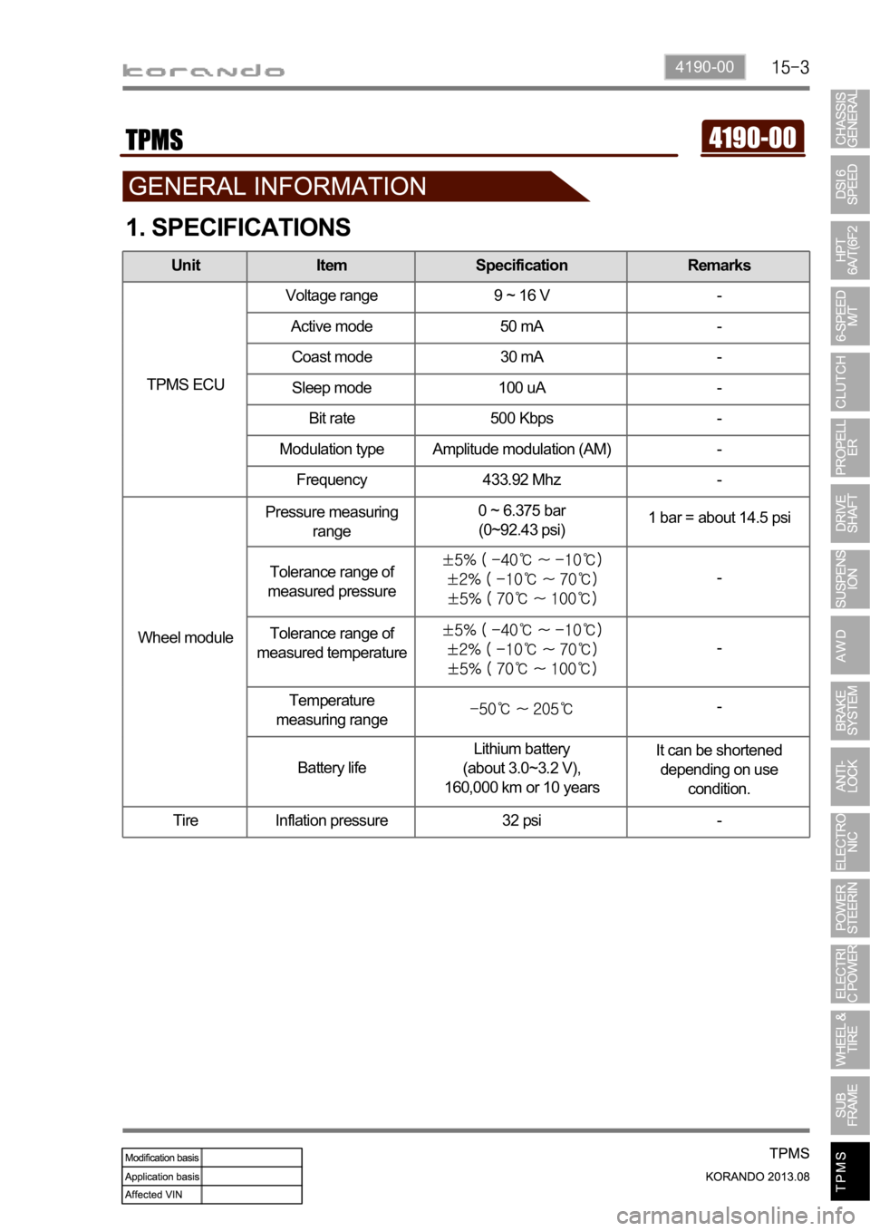
1. SPECIFICATIONS
Unit Item Specification Remarks
TPMS ECUVoltage range 9 ~ 16 V -
Active mode 50 mA -
Coast mode 30 mA -
Sleep mode 100 uA -
Bit rate 500 Kbps -
Modulation type Amplitude modulation (AM) -
Frequency 433.92 Mhz -
Wheel modulePressure measuring
range0 ~ 6.375 bar
(0~92.43 psi)1 bar = about 14.5 psi
Tolerance range of
measured pressure
-
Tolerance range of
measured temperature
-
Temperature
measuring range
-
Battery lifeLithium battery
(about 3.0~3.2 V),
160,000 km or 10 yearsIt can be shortened
depending on use
condition.
Tire Inflation pressure 32 psi -
Page 1172 of 1336

4190-00
3. CAUTIONS
The tire pressure values displayed on the instrument cluster are sent from the wheel modules after
the vehicle is driven for a period of time. Therefore, they are not displayed at initial start (more than
20 minutes have elapsed after ignition off). It can be displayed after 10 minutes of driving at speed of
20 km/h or higher. -
The TPMS uses a radio frequency and a high frequency band between the wheel module and the
TPMS ECU for communication.
Therefore, if the vehicle is equipped with the electronic equipment such as mobile camera monitor
or the vehicle is passing through the area with a strong electromagnetic field, the system may not
operate normally.
For the vehicle equipped with the TPMS, the TPMS warning lamp on the instrument cluster comes
on and pressure values on the EL display is displayed as bars (--) after driving for a certain period of
time if a newly installed tire is not equipped with the wheel module. -
-
At initial startDisplay pressure value after
detecting
position automatically
Standard type
Supervision type
Page 1175 of 1336

Instrument cluster display related to TPMS (with standard)
DOT LCD display TPMS warning lamp Global warning lamp
2. LAYOUT 1. OVERVIEW
The TPMS is used to reduce the accident rate, enhance driving stability and avoid an unnecessary fuel
consumption and tire wear by monitoring the tire pressure and temperature to inform the driver of tire
pressure information and its status through the instrument cluster. The wheel module fitted in the tire
transmits the internal data for the tire to the TPMS ECU periodically through the wireless transmission.
The TPMS ECU can detect the positions of the wheel modules fitted to each wheel automatically and
sends the signal on tire condition through the CAN line to the instrument cluster so that the driver can
identify the wheel module in question.
Instrument cluster display related to TPMS (with supervision)
DOT LCD display TPMS warning lamp Global warning lamp
Page 1176 of 1336

4190-00
Wheel module
The wheel modules are mounted to each wheel rim and hole.
TPMS ECU
The TPMS ECU is mounted to the rear bumper beam.