ECU SSANGYONG KORANDO 2013 Owners Manual
[x] Cancel search | Manufacturer: SSANGYONG, Model Year: 2013, Model line: KORANDO, Model: SSANGYONG KORANDO 2013Pages: 1336, PDF Size: 92.18 MB
Page 956 of 1336

Circuit diagram of ECU
Internal circuit diagram of sensors
Page 976 of 1336
![SSANGYONG KORANDO 2013 Owners Manual Press the [4INT] button repeatedly to select the intro play mode.
- INT: Play the intro of all the songs in the current folder in order for about 10 seconds (applies
only to MP3/WMA disc)
- IN SSANGYONG KORANDO 2013 Owners Manual Press the [4INT] button repeatedly to select the intro play mode.
- INT: Play the intro of all the songs in the current folder in order for about 10 seconds (applies
only to MP3/WMA disc)
- IN](/img/67/57503/w960_57503-975.png)
Press the [4INT] button repeatedly to select the intro play mode.
- INT: Play the intro of all the songs in the current folder in order for about 10 seconds (applies
only to MP3/WMA disc)
- INT: Play the intro of all the song in the disc in order for about 10 seconds
- OFF: Deactivates playing intro 2.To change play mode
Press the [2RPT] button repeatedly to select the repeat mode.
- RPT: Repeat all the songs in the current folder in order (applies only to MP3/WMA disc)
- RPT: Repeat the playing song consecutively
- OFF: Deactivates repeat mode 1.
Search for song and play it
When [MENU] button is pressed after turning the [TUNE] dial to select the song number or name to
play, the system begins playing the song. 1.
MP3[WMA] song information view
If you press the [INF] button briefly and repeatedly when a song is playing, other information
(artist/album/genre/play time) for the song is displayed for 3 seconds.
If you press and hold the [INF] button when a song is playing, the data table for the song is displayed
for 5 seconds. 1.
2.
To set scroll function
When pressing the [SET] button, "Setup List" is displayed.
Turn the [TUNE] dial to select the desired "Scroll On/Off" and press the [ENTER] button to select ON
or OFF. 1.
2.Press the [5RDM] button repeatedly to select the random play mode.
- RDM: Play all the songs in the current folder in random order
(applies only to MP3/WMA disc)
- RDM: Play all the song in the disc in random order
- OFF: Deactivates random play mode 3.
8. MP3 [WMA]/CD PLAYER
Page 983 of 1336

0000-00
Wheel module
The wheel modules are mounted to each wheel rim and hole. They transmit
the signal of the pressure and temperature in tire, rotating direction and
wheel module ID code, etc. using the radio frequency to the TPMS ECU.
TPMS ECU
The TPMS ECU is located to the rear bumper rail under the vehicle. It outputs the tire pressure
information and CAN data.
Page 984 of 1336
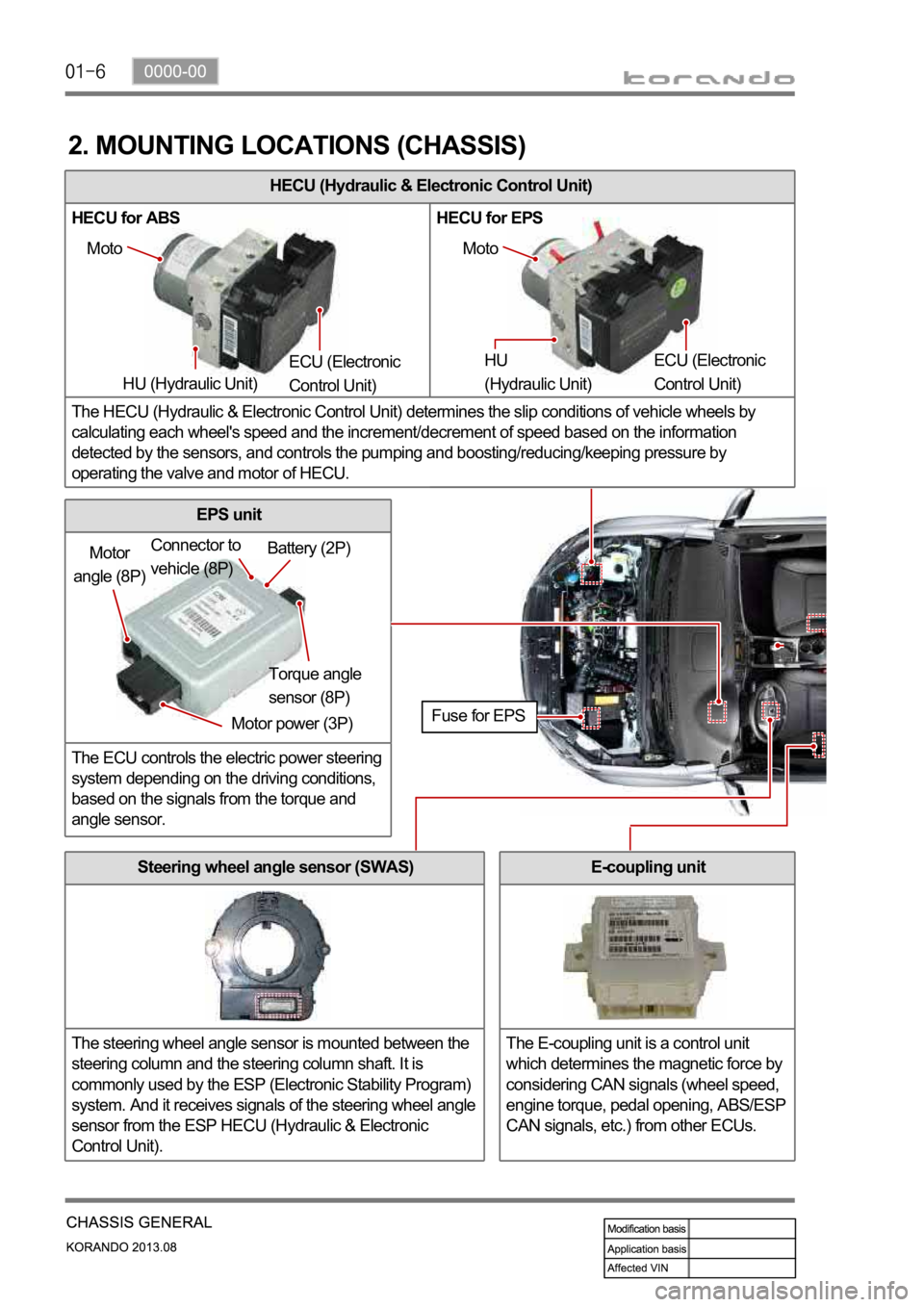
HECU (Hydraulic & Electronic Control Unit)
HECU for ABS HECU for EPS
The HECU (Hydraulic & Electronic Control Unit) determines the slip conditions of vehicle wheels by
calculating each wheel's speed and the increment/decrement of speed based on the information
detected by the sensors, and controls the pumping and boosting/reducing/keeping pressure by
operating the valve and motor of HECU.
2. MOUNTING LOCATIONS (CHASSIS)
Moto
HU (Hydraulic Unit) ECU (Electronic
Control Unit) Moto
HU
(Hydraulic Unit) ECU (Electronic
Control Unit)
Motor
angle (8P)
Motor power (3P)Torque angle
sensor (8P) Battery (2P) Connector to
vehicle (8P)
Fuse for EPS
Steering wheel angle sensor (SWAS)
The steering wheel angle sensor is mounted between the
steering column and the steering column shaft. It is
commonly used by the ESP (Electronic Stability Program)
system. And it receives signals of the steering wheel angle
sensor from the ESP HECU (Hydraulic & Electronic
Control Unit).
EPS unit
The ECU controls the electric power steering
system depending on the driving conditions,
based on the signals from the torque and
angle sensor.
E-coupling unit
The E-coupling unit is a control unit
which determines the magnetic force by
considering CAN signals (wheel speed,
engine torque, pedal opening, ABS/ESP
CAN signals, etc.) from other ECUs.
Page 985 of 1336
0000-00
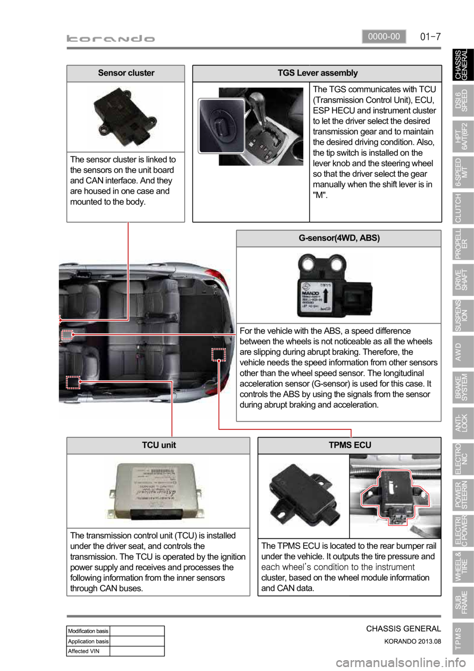
TPMS ECU
The TPMS ECU is located to the rear bumper rail
under the vehicle. It outputs the tire pressure and
cluster, based on the wheel module information
and CAN data.
G-sensor(4WD, ABS)
For the vehicle with the ABS, a speed difference
between the wheels is not noticeable as all the wheels
are slipping during abrupt braking. Therefore, the
vehicle needs the speed information from other sensors
other than the wheel speed sensor. The longitudinal
acceleration sensor (G-sensor) is used for this case. It
controls the ABS by using the signals from the sensor
during abrupt braking and acceleration.
TCU unit
The transmission control unit (TCU) is installed
under the driver seat, and controls the
transmission. The TCU is operated by the ignition
power supply and receives and processes the
following information from the inner sensors
through CAN buses.
TGS Lever assembly
The TGS communicates with TCU
(Transmission Control Unit), ECU,
ESP HECU and instrument cluster
to let the driver select the desired
transmission gear and to maintain
the desired driving condition. Also,
the tip switch is installed on the
lever knob and the steering wheel
so that the driver select the gear
manually when the shift lever is in
"M".Sensor cluster
The sensor cluster is linked to
the sensors on the unit board
and CAN interface. And they
are housed in one case and
mounted to the body.
Page 986 of 1336
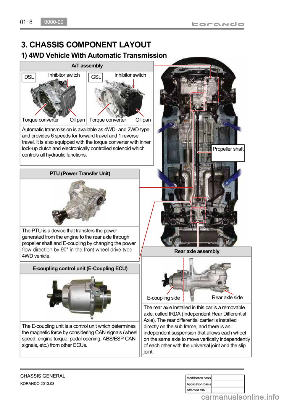
A/T assembly
Automatic transmission is available as 4WD- and 2WD-type,
and provides 6 speeds for forward travel and 1 reverse
travel. It is also equipped with the torque converter with inner
lock-up clutch and electronically controlled solenoid which
controls all hydraulic functions.
3. CHASSIS COMPONENT LAYOUT
PTU (Power Transfer Unit)
The PTU is a device that transfers the power
generated from the engine to the rear axle through
propeller shaft and E-coupling by changing the power
4WD vehicle.Rear axle assembly
The rear axle installed in this car is a removable
axle, called IRDA (Independent Rear Differential
Axle). The rear differential carrier is installed
directly on the sub frame, and there is an
independent suspension that allows each wheel
on the same axle to move vertically independentl
y
of each other with the universal joint and the slip
joint.
E-coupling control unit (E-Coupling ECU)
The E-coupling unit is a control unit which determines
the magnetic force by considering CAN signals (wheel
speed, engine torque, pedal opening, ABS/ESP CAN
signals, etc.) from other ECUs.
Inhibitor switch
Torque converter Oil pan
E-coupling sideRear axle side
Propeller shaft
1) 4WD Vehicle With Automatic Transmission
GSLDSLInhibitor switch
Torque converter Oil pan
Page 994 of 1336

A. Indicators on instrument cluster
C. HECU assembly
The HECU assemblies for ABS and ESP have
similar appearance but they have different inner
structure and connector connections from each
other. D. Front brake assembly
The disc brake for 4WD vehicle is the same with
the one for 2WD vehicle.
7. BRAKE SYSTEM AND ESP SYSTEM LAYOUT
B. Master cylinder assembly
Description for master cylinder in this chapter is
based on ABS/ESP equipped vehicle. For CBS,
there is an extra pressure valve mounted to the
master cylinder.
CaliperDisc
Parking brake
warning light
ABS warning lamp
ESP indicator
Page 997 of 1336
0000-00
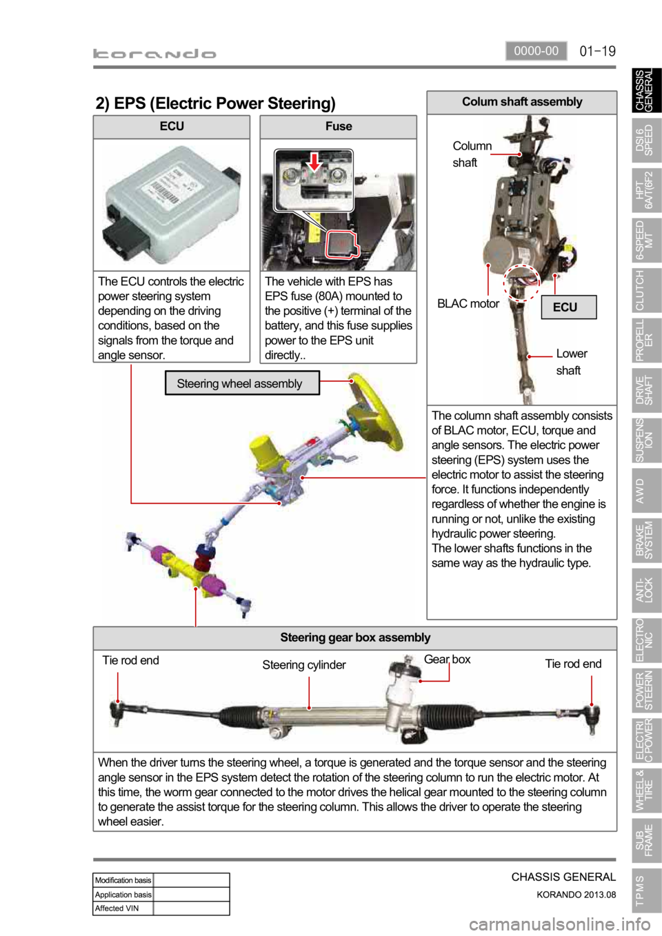
ECU
The ECU controls the electric
power steering system
depending on the driving
conditions, based on the
signals from the torque and
angle sensor.
2) EPS (Electric Power Steering)
Fuse
The vehicle with EPS has
EPS fuse (80A) mounted to
the positive (+) terminal of the
battery, and this fuse supplies
power to the EPS unit
directly..
Steering gear box assembly
When the driver turns the steering wheel, a torque is generated and the torque sensor and the steering
angle sensor in the EPS system detect the rotation of the steering column to run the electric motor. At
this time, the worm gear connected to the motor drives the helical gear mounted to the steering column
to generate the assist torque for the steering column. This allows the driver to operate the steering
wheel easier.
ECU
Tie rod end
Tie rod end Gear boxSteering cylinder
Steering wheel assembly
BLAC motor
Lower
shaft Column
shaft
Colum shaft assembly
The column shaft assembly consists
of BLAC motor, ECU, torque and
angle sensors. The electric power
steering (EPS) system uses the
electric motor to assist the steering
force. It functions independently
regardless of whether the engine is
running or not, unlike the existing
hydraulic power steering.
The lower shafts functions in the
same way as the hydraulic type.
Page 1016 of 1336
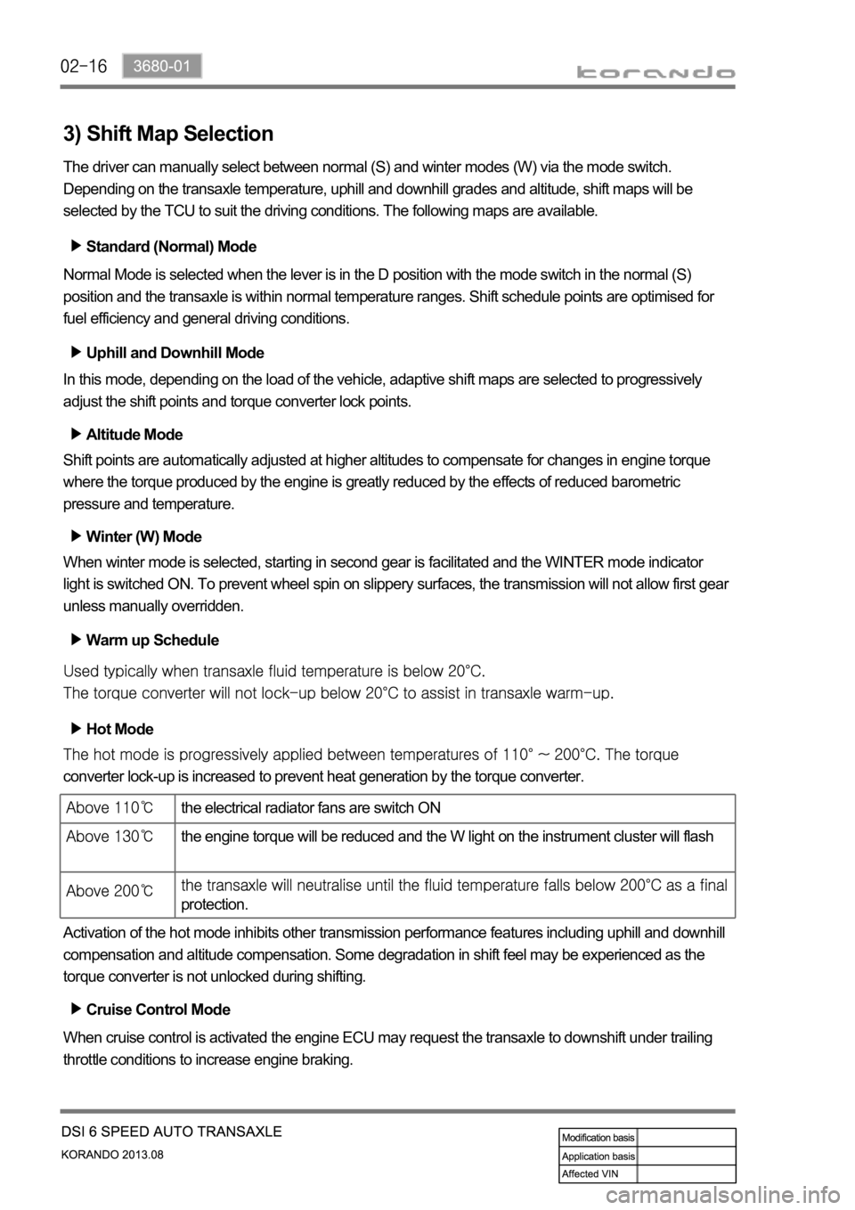
3) Shift Map Selection
The driver can manually select between normal (S) and winter modes (W) via the mode switch.
Depending on the transaxle temperature, uphill and downhill grades and altitude, shift maps will be
selected by the TCU to suit the driving conditions. The following maps are available.
Standard (Normal) Mode
Normal Mode is selected when the lever is in the D position with the mode switch in the normal (S)
position and the transaxle is within normal temperature ranges. Shift schedule points are optimised for
fuel efficiency and general driving conditions.
Uphill and Downhill Mode
In this mode, depending on the load of the vehicle, adaptive shift maps are selected to progressively
adjust the shift points and torque converter lock points.
Altitude Mode
Shift points are automatically adjusted at higher altitudes to compensate for changes in engine torque
where the torque produced by the engine is greatly reduced by the effects of reduced barometric
pressure and temperature.
Winter (W) Mode
When winter mode is selected, starting in second gear is facilitated and the WINTER mode indicator
light is switched ON. To prevent wheel spin on slippery surfaces, the transmission will not allow first gear
unless manually overridden.
Warm up Schedule
Hot Mode
converter lock-up is increased to prevent heat generation by the torque converter.
Activation of the hot mode inhibits other transmission performance features including uphill and downhill
compensation and altitude compensation. Some degradation in shift feel may be experienced as the
torque converter is not unlocked during shifting.
Cruise Control Mode
When cruise control is activated the engine ECU may request the transaxle to downshift under trailing
throttle conditions to increase engine braking.
the electrical radiator fans are switch ON
the engine torque will be reduced and the W light on the instrument cluster will flash
protection.
Page 1058 of 1336
3190-01
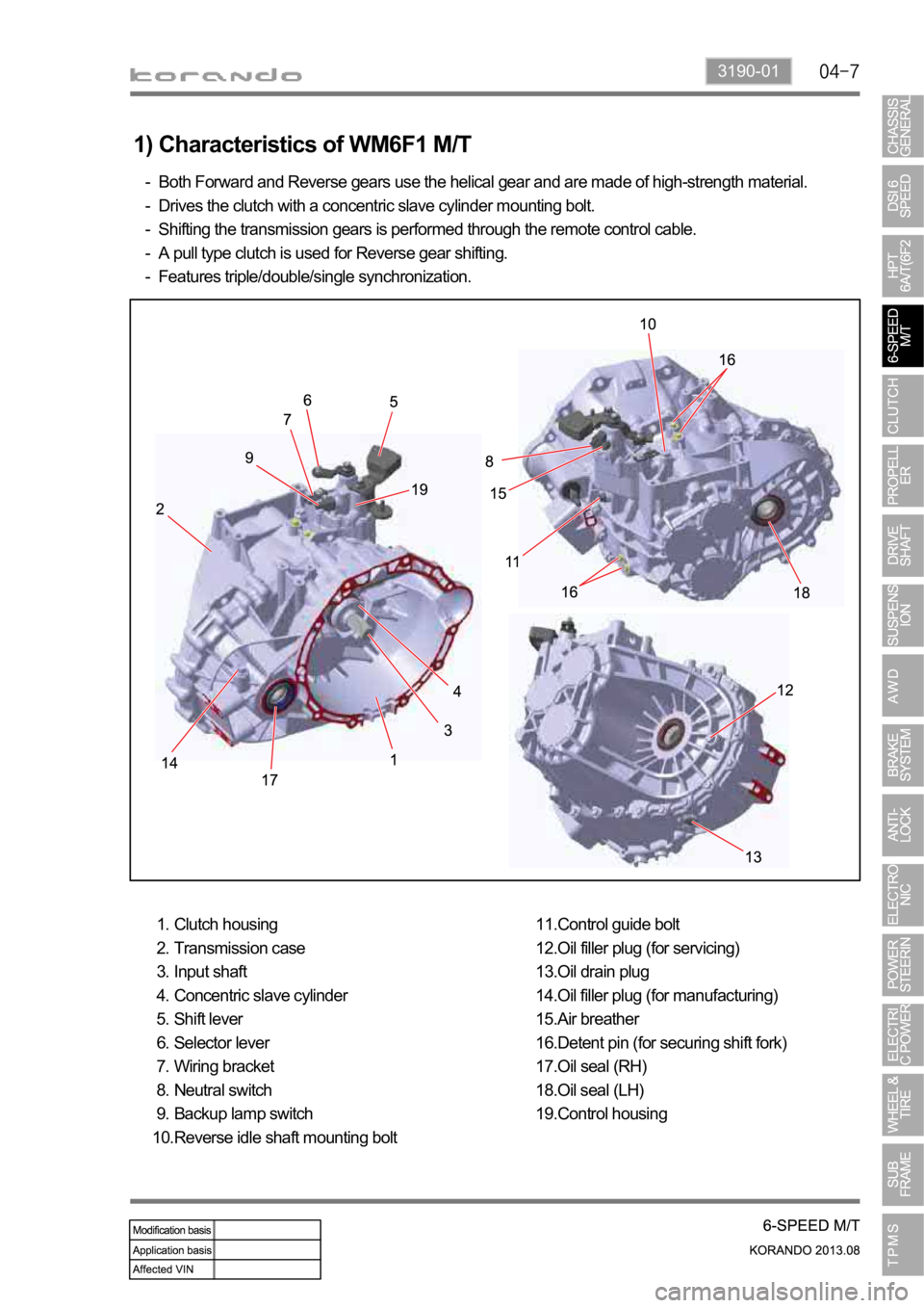
1) Characteristics of WM6F1 M/T
Both Forward and Reverse gears use the helical gear and are made of high-strength material.
Drives the clutch with a concentric slave cylinder mounting bolt.
Shifting the transmission gears is performed through the remote control cable.
A pull type clutch is used for Reverse gear shifting.
Features triple/double/single synchronization. -
-
-
-
-
Clutch housing
Transmission case
Input shaft
Concentric slave cylinder
Shift lever
Selector lever
Wiring bracket
Neutral switch
Backup lamp switch
Reverse idle shaft mounting bolt 1.
2.
3.
4.
5.
6.
7.
8.
9.
10.Control guide bolt
Oil filler plug (for servicing)
Oil drain plug
Oil filler plug (for manufacturing)
Air breather
Detent pin (for securing shift fork)
Oil seal (RH)
Oil seal (LH)
Control housing 11.
12.
13.
14.
15.
16.
17.
18.
19.