ECU SSANGYONG KORANDO 2013 Service Manual
[x] Cancel search | Manufacturer: SSANGYONG, Model Year: 2013, Model line: KORANDO, Model: SSANGYONG KORANDO 2013Pages: 1336, PDF Size: 92.18 MB
Page 1108 of 1336

5. SYSTEM OPERATION
1) Block Diagram of ABS HECU
Page 1116 of 1336
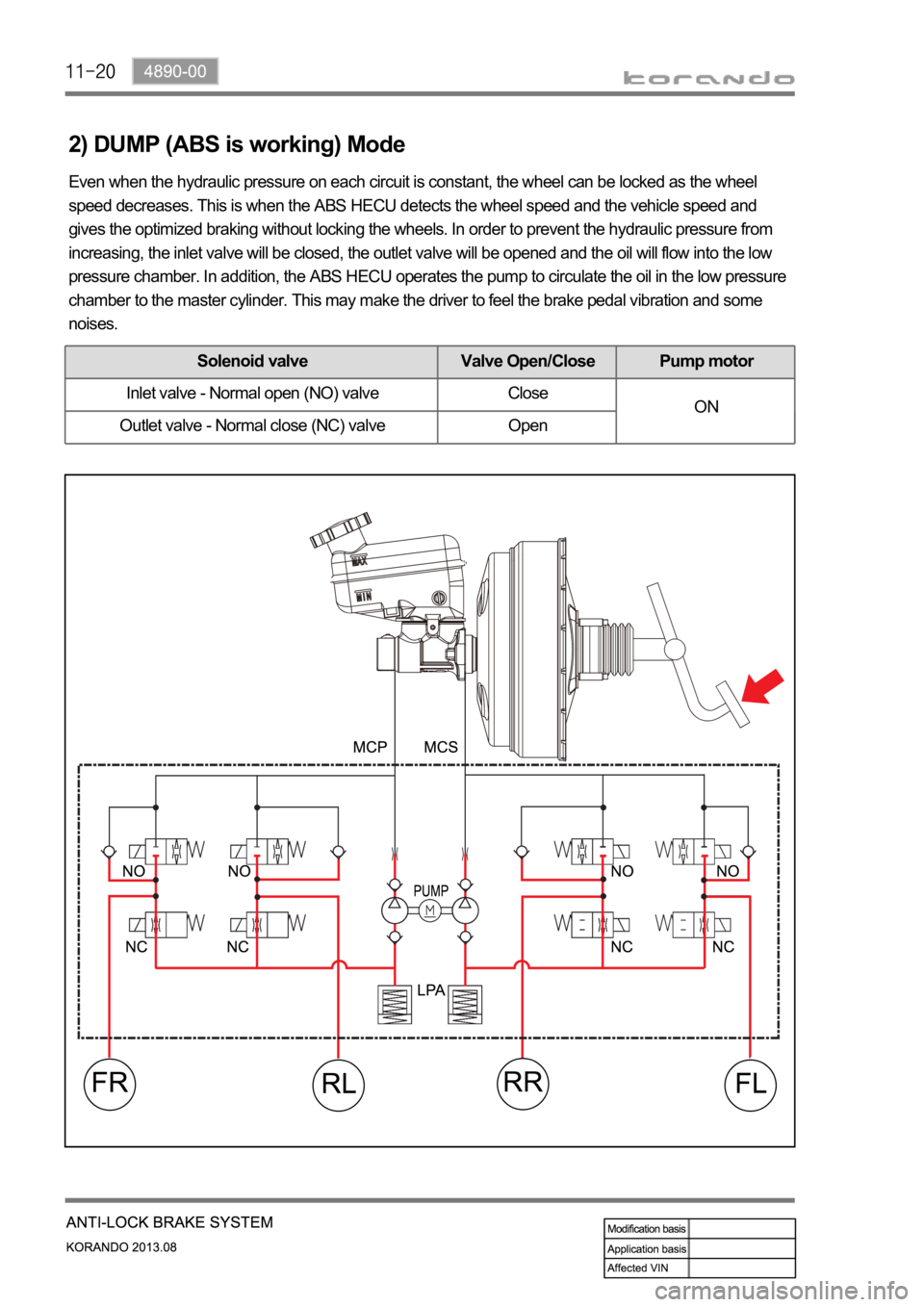
2) DUMP (ABS is working) Mode
Even when the hydraulic pressure on each circuit is constant, the wheel can be locked as the wheel
speed decreases. This is when the ABS HECU detects the wheel speed and the vehicle speed and
gives the optimized braking without locking the wheels. In order to prevent the hydraulic pressure from
increasing, the inlet valve will be closed, the outlet valve will be opened and the oil will flow into the low
pressure chamber. In addition, the ABS HECU operates the pump to circulate the oil in the low pressure
chamber to the master cylinder. This may make the driver to feel the brake pedal vibration and some
noises.
Solenoid valve Valve Open/Close Pump motor
Inlet valve - Normal open (NO) valve Close
ON
Outlet valve - Normal close (NC) valve Open
Page 1118 of 1336
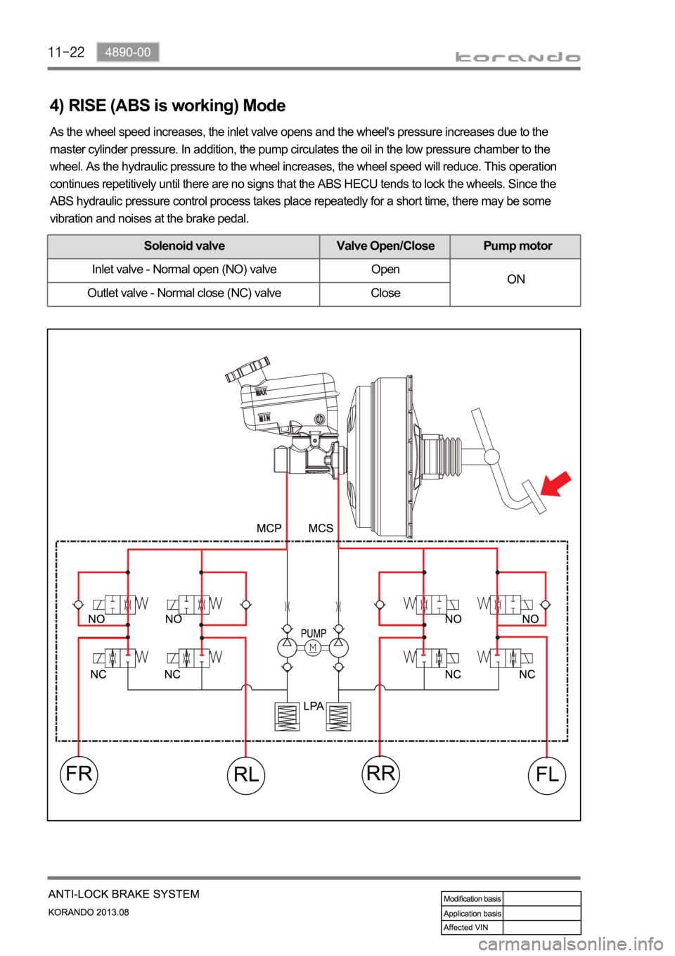
4) RISE (ABS is working) Mode
As the wheel speed increases, the inlet valve opens and the wheel's pressure increases due to the
master cylinder pressure. In addition, the pump circulates the oil in the low pressure chamber to the
wheel. As the hydraulic pressure to the wheel increases, the wheel speed will reduce. This operation
continues repetitively until there are no signs that the ABS HECU tends to lock the wheels. Since the
ABS hydraulic pressure control process takes place repeatedly for a short time, there may be some
vibration and noises at the brake pedal.
Solenoid valve Valve Open/Close Pump motor
Inlet valve - Normal open (NO) valve Open
ON
Outlet valve - Normal close (NC) valve Close
Page 1120 of 1336
0000-00
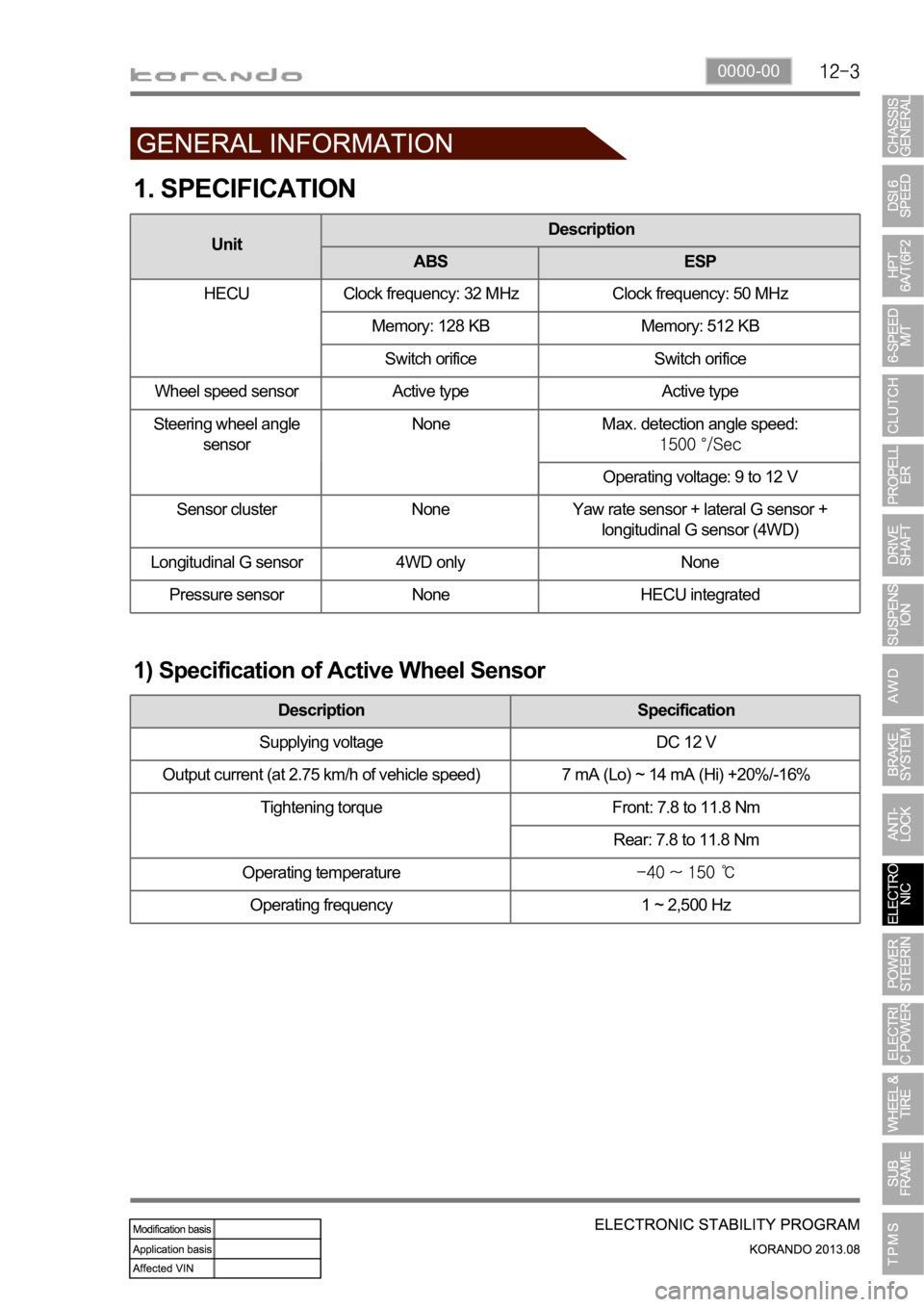
1. SPECIFICATION
1) Specification of Active Wheel Sensor
Description Specification
Supplying voltage DC 12 V
Output current (at 2.75 km/h of vehicle speed) 7 mA (Lo) ~ 14 mA (Hi) +20%/-16%
Tightening torque Front: 7.8 to 11.8 Nm
Rear: 7.8 to 11.8 Nm
Operating temperature
Operating frequency 1 ~ 2,500 Hz
UnitDescription
ABS ESP
HECU Clock frequency: 32 MHz Clock frequency: 50 MHz
Memory: 128 KB Memory: 512 KB
Switch orifice Switch orifice
Wheel speed sensor Active type Active type
Steering wheel angle
sensorNone Max. detection angle speed:
Operating voltage: 9 to 12 V
Sensor cluster None Yaw rate sensor + lateral G sensor +
longitudinal G sensor (4WD)
Longitudinal G sensor 4WD only None
Pressure sensor None HECU integrated
Page 1122 of 1336

0000-00
1. OVERVIEW
The ESP (Electronic Stability Program) has been developed to help a driver avoid danger of losing
control of the vehicle stability due to understeer or oversteer during cornering. The yaw rate sensor,
lateral sensor and longitudinal sensor in the sensor cluster and the steering wheel angle sensor under
the steering column detect the vehicle conditions when the inner or outer wheels are spinning during
oversteer, understeer or cornering. The ESP ECU controls against oversteer or understeer during
cornering by controlling the vehicle stability using input values from these sensors and applying the
braking force to the corresponding wheels independently. The system also controls the engine power
right before the wheel spin synchronized to decelerate the vehicle automatically in order to maintain the
vehicle stable during cornering.
Page 1123 of 1336
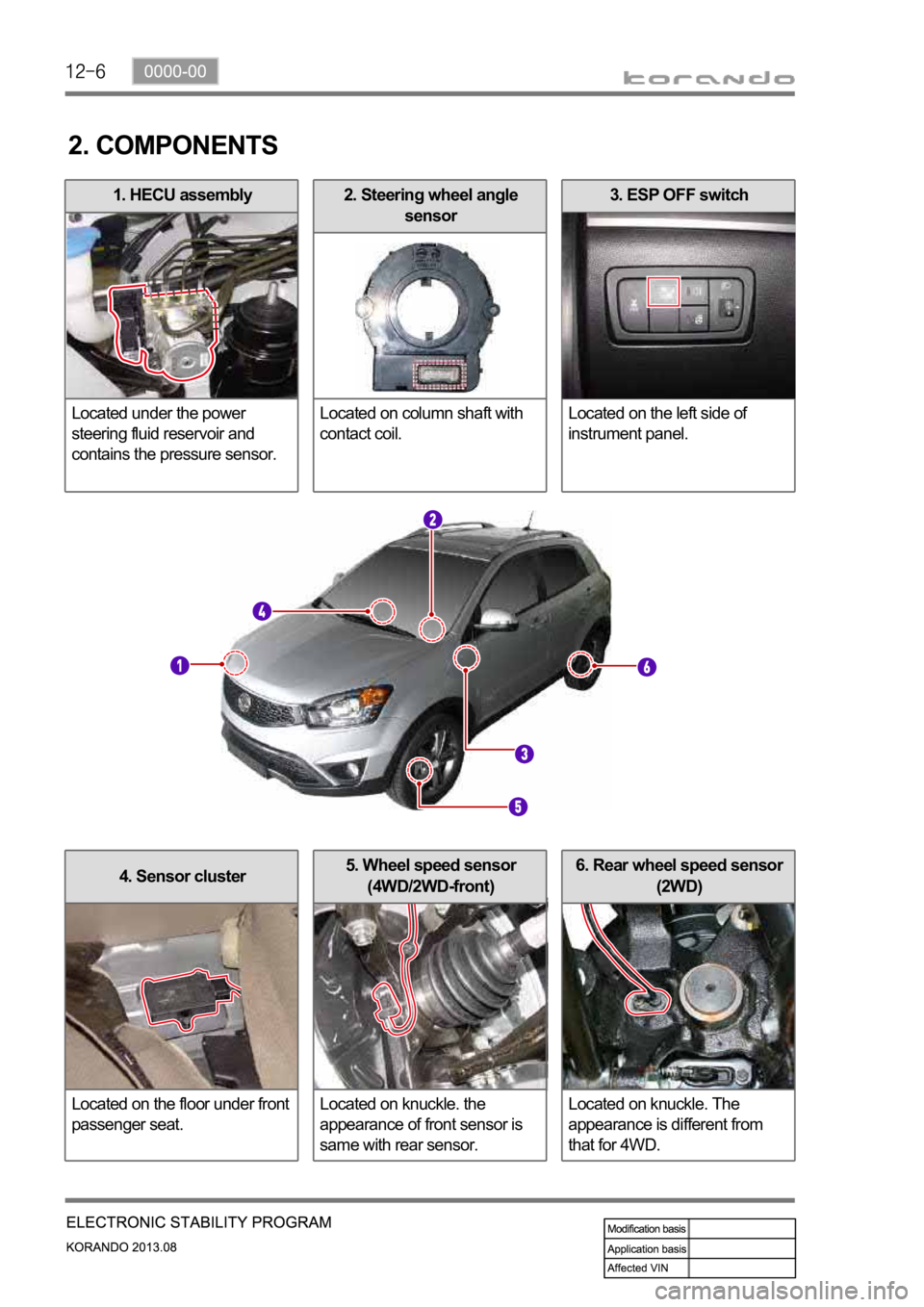
3. ESP OFF switch
Located on the left side of
instrument panel.2. Steering wheel angle
sensor
Located on column shaft with
contact coil.1. HECU assembly
Located under the power
steering fluid reservoir and
contains the pressure sensor.
2. COMPONENTS
4. Sensor cluster
Located on the floor under front
passenger seat.5. Wheel speed sensor
(4WD/2WD-front)
Located on knuckle. the
appearance of front sensor is
same with rear sensor.6. Rear wheel speed sensor
(2WD)
Located on knuckle. The
appearance is different from
that for 4WD.
Page 1125 of 1336

4. WARNING LAMPS
1) ABS
ABS warning lamp module indicates the self-diagnosis and malfunction.
ABS warning lamp ON: Warning Lamp
When turning the ignition switch to ON position, ABS warning lamp comes on for 3 seconds for self-
diagnosis and goes off if the system is OK (initialization mode).
When the system is defective, the warning lamp comes on.
When the self-diagnosis is performing, the warning lamp comes on.
When the HECU connector is disconnected, the warning lamp comes on.
ABS is not available during lamp ON. In this condition, Only normal brake system without ABS
function is available.
When the communication between warning lamp CAN module in meter cluster, the warning lamp
comes on. 1.
2.
3.
4.
5.
6.ABS warning lamp
Brake warning lamp
ESP OFF indicator
ESP warning lamp/indicator
EBD warning lamp 1.
2.
3.
4.
5.
Page 1126 of 1336

0000-00
2) EBD (Electronic Brake-force Distribution) Warning Lamp (Brake
Warning Lamp)
EBD warning lamp when the system perform the self diagnosis and when it detects the malfunction of
EBD system. However, the brake warning lamp comes on regardless of EBD when the parking brake is
applied.
EBD warning lamp ON:
When turning the ignition switch to ON position, ABS warning lamp and the brake warning lamp
comes on for 3 seconds for self diagnosis and goes off if the system is OK (initialization mode).
When applying the parking brake, the brake warning lamp comes on.
When the brake fluid is not sufficient, the brake warning lamp comes on.
When the self-diagnosis is performing, the warning lamp comes on.
When the HECU connector is disconnected, the warning lamp comes on.
When the system is defective, ABS warning lamp and the brake warning lamp come on
simultaneously. 1.
2.
3.
4.
5.
6.
When the solenoid valve is defective
When one or more wheel sensors are defective
When ABS HECU is defective
When the voltage is abnormal
When valve relay is defective a.
b.
c.
d.
e.
When the communication between warning lamp CAN module in meter cluster, the warning lamp
comes on. 7.
3) ESP OFF Indicator
ESP OFF indicator ON:
When turning the ignition switch to ON position, ESP warning lamp comes on for 3 seconds for self
diagnosis and goes off if the system is OK (initialization mode).
When the ESP OFF switch is pressed to turn off ESP function, ESP OFF indicator comes on. 1.
2.
4) ESP Warning Lamp
ESP warning lamp ON:
When turning the ignition switch to ON position, ESP warning lamp comes on for 3 seconds for self
diagnosis and goes off if the system is OK (initialization mode).
When the system is defective, the warning lamp comes on.
When the ESP function is activated, ESP warning lamp blinks with the interval of 2 Hz.
When the communication between warning lamp CAN module in meter cluster, the warning lamp
comes on. 1.
2.
3.
4.
5.
5) ESP OFF Switch
If ESP OFF switch is pressed, ESP function is deactivated and the ESP OFF indicator in the instrument
cluster comes on.
To resume the ESP function, press the switch again. At this time, ESP OFF indicator goes out.
Page 1127 of 1336

5. SYSTEM DESCRIPTION
1) Block Diagram of ESP HECU
Page 1128 of 1336
0000-00
2) Operation of ESP System
The ESP (Electronic Stability Program) has been developed to help a driver avoid danger of losing
control of the vehicle stability due to understeer or oversteer during cornering. The yaw rate sensor,
lateral sensor and longitudinal sensor in the sensor cluster and the steering wheel angle sensor under
the steering column detect the vehicle conditions when the inner or outer wheels are spinning during
oversteer, understeer or cornering. The ESP ECU controls against oversteer or understeer during
cornering by controlling the vehicle stability using input values from these sensors and applying the
braking force to the corresponding wheels independently. The system also controls the engine power
right before the wheel spin synchronized with the ASR function to decelerate the vehicle automatically in
order to maintain the vehicle stable during cornering.
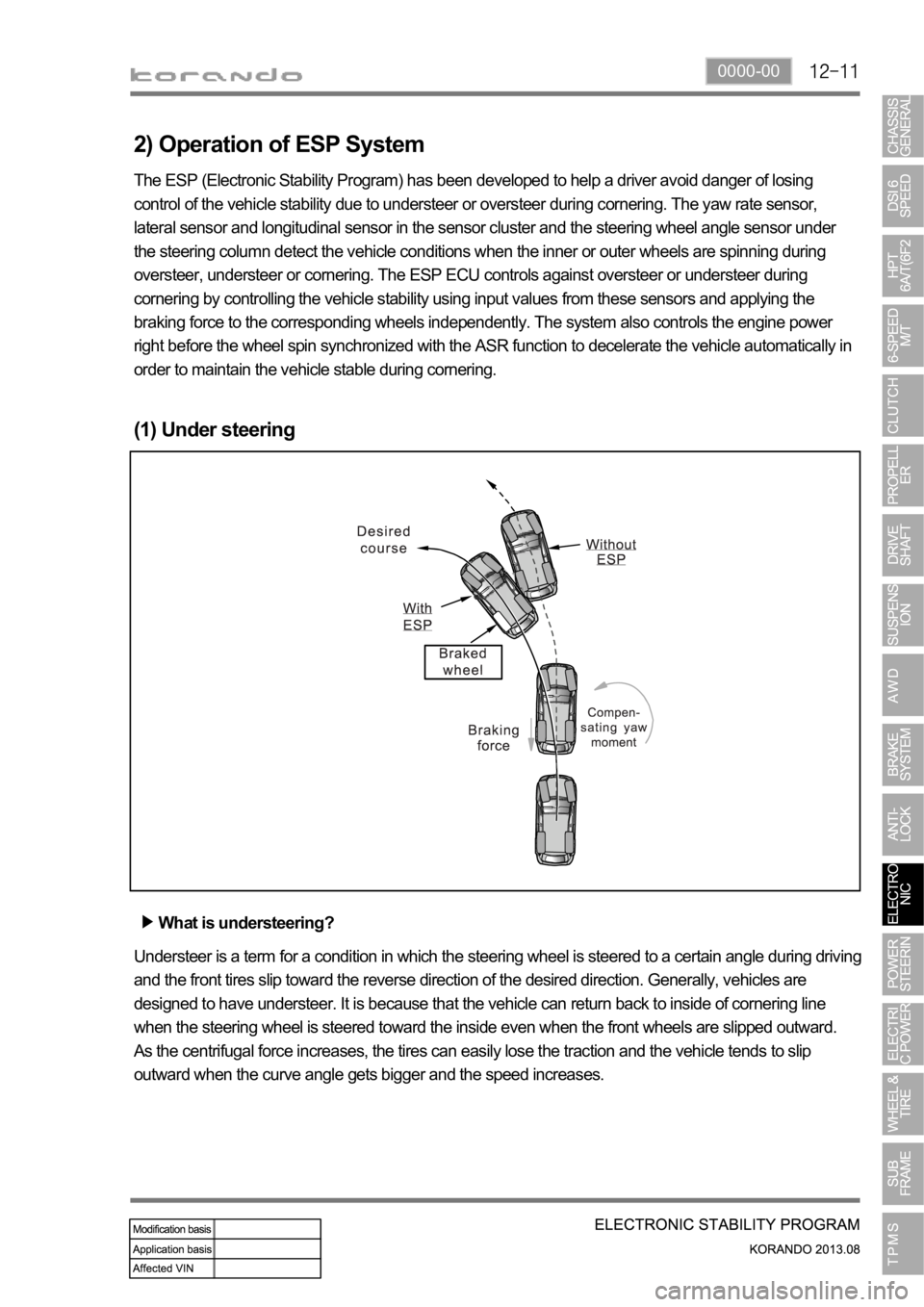
(1) Under steering
What is understeering?
Understeer is a term for a condition in which the steering wheel is steered to a certain angle during driving
and the front tires slip toward the reverse direction of the desired direction. Generally, vehicles are
designed to have understeer. It is because that the vehicle can return back to inside of cornering line
when the steering wheel is steered toward the inside even when the front wheels are slipped outward.
As the centrifugal force increases, the tires can easily lose the traction and the vehicle tends to slip
outward when the curve angle gets bigger and the speed increases.