ECU SSANGYONG KORANDO 2013 Manual Online
[x] Cancel search | Manufacturer: SSANGYONG, Model Year: 2013, Model line: KORANDO, Model: SSANGYONG KORANDO 2013Pages: 1336, PDF Size: 92.18 MB
Page 752 of 1336

3) Immobilizer Ignition Key Verification
When turning the ignition key to the ON position, the power is supplied to the immobilizer unit and EMS
(ECU). The ECU communicates with the immobilizer unit to verify the key and transponder. If it is valid,
the ECU starts to control the engine or immobilizer indicator (illumination or flashing) when the ignition key
is turned to the START position.
Once the key is verified, valid key verification time is provided for 10 seconds and the engine can be
started by turning the ignition key to the engine START position during this verification time. If the ignition
key is turned to the START position again after the 10 seconds of verification time, the key verification
should be reperformed.
When the ignition key is inserted, the immobilizer unit requests the transponder verification through
the antenna.
The transponder sends the encrypted message to the immobilizer control unit.
The immobilizer unit compares the encrypted message received from the transponder to the
coded value through the logic circuit. If they are identical, it requests the transponder approval.
When the ignition is turned ON, the EMS (ECU) requests immobilizer verification process through
the P-CAN.
The immobilizer control unit sends the encrypted message to the EMS (ECU).
The EMS controls the engine normally when the coded value and the encrypted message sent
from the immobilizer are identical. 1.
2.
3.
4.
5.
6.
When the immobilizer verification has failed, the verification signal is sent again 3 times for 2
seconds, and the verification procedure is carried out up to 3 times by turning the ignition ON within
10 seconds. If the three re-verifications fail, verification procedure is stopped and will be restarted
after 10 seconds.
Page 754 of 1336
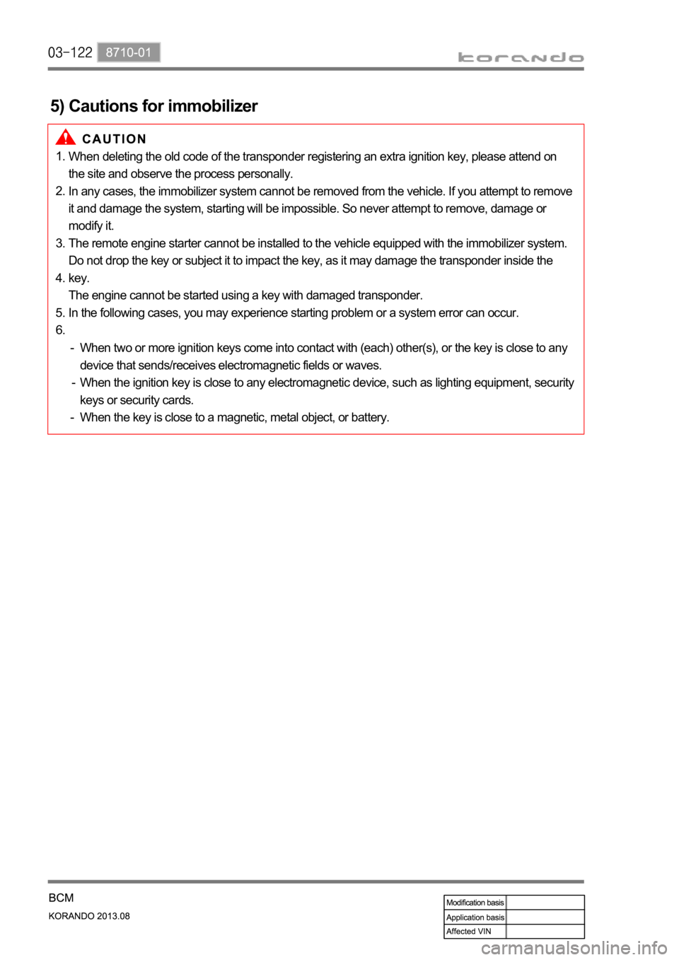
When deleting the old code of the transponder registering an extra ignition key, please attend on
the site and observe the process personally.
In any cases, the immobilizer system cannot be removed from the vehicle. If you attempt to remove
it and damage the system, starting will be impossible. So never attempt to remove, damage or
modify it.
The remote engine starter cannot be installed to the vehicle equipped with the immobilizer system.
Do not drop the key or subject it to impact the key, as it may damage the transponder inside the
key.
The engine cannot be started using a key with damaged transponder.
In the following cases, you may experience starting problem or a system error can occur. 1.
2.
3.
4.
5.
6.
5) Cautions for immobilizer
When two or more ignition keys come into contact with (each) other(s), or the key is close to any
device that sends/receives electromagnetic fields or waves.
When the ignition key is close to any electromagnetic device, such as lighting equipment, security
keys or security cards.
When the key is close to a magnetic, metal object, or battery. -
-
-
Page 771 of 1336
8712-03
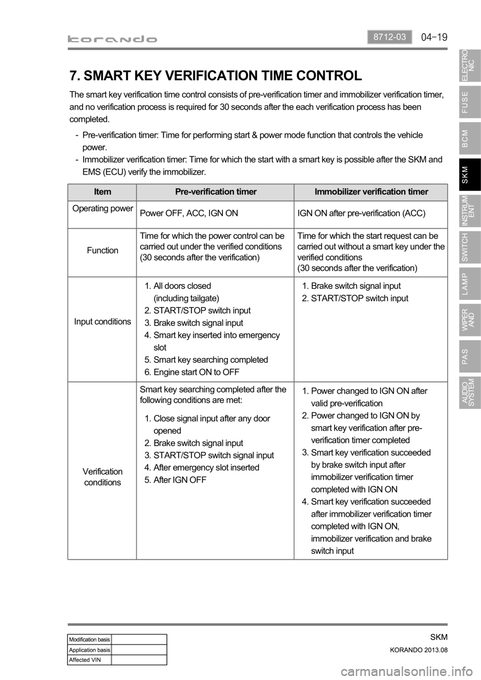
7. SMART KEY VERIFICATION TIME CONTROL
The smart key verification time control consists of pre-verification timer and immobilizer verification timer,
and no verification process is required for 30 seconds after the each verification process has been
completed.
Pre-verification timer: Time for performing start & power mode function that controls the vehicle
power.
Immobilizer verification timer: Time for which the start with a smart key is possible after the SKM and
EMS (ECU) verify the immobilizer. -
-
Item Pre-verification timer Immobilizer verification timer
Operating power
Power OFF, ACC, IGN ON IGN ON after pre-verification (ACC)
FunctionTime for which the power control can be
carried out under the verified conditions
(30 seconds after the verification)Time for which the start request can be
carried out without a smart key under the
verified conditions
(30 seconds after the verification)
Input conditions
Verification
conditionsSmart key searching completed after the
following conditions are met:
Close signal input after any door
opened
Brake switch signal input
START/STOP switch signal input
After emergency slot inserted
After IGN OFF 1.
2.
3.
4.
5.Power changed to IGN ON after
valid pre-verification
Power changed to IGN ON by
smart key verification after pre-
verification timer completed
Smart key verification succeeded
by brake switch input after
immobilizer verification timer
completed with IGN ON
Smart key verification succeeded
after immobilizer verification timer
completed with IGN ON,
immobilizer verification and brake
switch input 1.
2.
3.
4. All doors closed
(including tailgate)
START/STOP switch input
Brake switch signal input
Smart key inserted into emergency
slot
Smart key searching completed
Engine start ON to OFF 1.
2.
3.
4.
5.
6.Brake switch signal input
START/STOP switch input 1.
2.
Page 774 of 1336
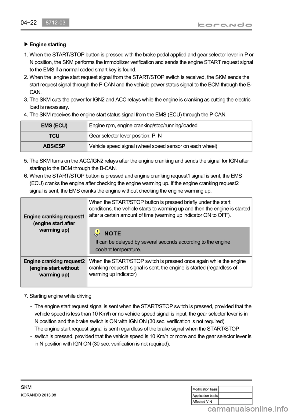
Engine starting
When the START/STOP button is pressed with the brake pedal applied and gear selector lever in P or
N position, the SKM performs the immobilizer verification and sends the engine START request signal
to the EMS if a normal coded smart key is found.
When the .engine start request signal from the START/STOP switch is received, the SKM sends the
start request signal through the P-CAN and the vehicle power status signal to the BCM through the B-
CAN.
The SKM cuts the power for IGN2 and ACC relays while the engine is cranking as cutting the electric
load is necessary.
The SKM receives the engine start status signal from the EMS (ECU) through the P-CAN. 1.
2.
3.
4.
EMS (ECU)Engine rpm, engine cranking/stop/running/loaded
TCUGear selector lever position: P, N
ABS/ESPVehicle speed signal (wheel speed sensor on each wheel)
The SKM turns on the ACC/IGN2 relays after the engine cranking and sends the signal for IGN after
starting to the BCM through the B-CAN.
When the START/STOP button is pressed and engine cranking request1 signal is sent, the EMS
(ECU) cranks the engine after checking the engine warming up. If the engine cranking request2
signal is sent, the EMS cranks the engine without checking the engine warming up. 5.
6.
Engine cranking request1
(engine start after
warming up)When the START/STOP button is pressed briefly under the start
conditions, the vehicle starts to warming up and then the engine is started
after a certain amount of time (warming up indicator ON to OFF).
Engine cranking request2
(engine start without
warming up)When the START/STOP switch is pressed once again while the engine
cranking request1 signal is sent, the engine is started (regardless of
warming up indicator)
It can be delayed by several seconds according to the engine
coolant temperature.
Starting engine while driving 7.
The engine start request signal is sent when the START/STOP switch is pressed, provided that the
vehicle speed is less than 10 Km/h or no vehicle speed signal is input, the gear selector lever is in
N position and the brake switch is ON with IGN ON (30 sec. verification is not required).
The engine start request signal is sent regardless of the brake signal when the START/STOP
switch is pressed, provided that the vehicle speed is 10 Km/h or more and the gear selector lever is
in N position with IGN ON (30 sec. verification is not required). -
-
Page 785 of 1336

8712-03
Start motor
12. SKM IMMOBILIZER SYSTEM
1) System Description
The immobilizer system prevents the vehicle theft by allowing only the authorized key to start the engine.
The transponder inside the key communicates with the SKM (immobilizer slot) and EMS (ECU) through
P-CAN communication, and the system permits the engine to start after confirming the encrypted
coding.
When the START/STOP switch is pressed with the smart key inserted into the immobilizer slot because
of the smart key battery discharge, the SKM communicates with the EMS (ECU) through P-CAN, and
the ECU starts to control the engine only the signal is valid.
A valid key verification time is provided for 10 seconds and the engine can be started during this time. If
pressing the START/STOP switch again after this 10 seconds, the key verification process is performed
again.
2) Configuration
Emergency slot
Smart key
SKM
EMS (ECU)
Page 786 of 1336

3) Operating Process
Key verification can be divided into two types, immobilizer key verification and smart key verification. The
immobilizer verification is applied for the SKM system, and verifies the transponder built in the smart key.
When the smart key is inserted into the slot, the verification is carried out, overriding the RF signal from
the smart key.
The power is supplied to the slot when the START/STOP switch is pressed with the smart key inserted
into the slot, and the smart key transponder verification is carried out by the transponder communication.
Once the key is verified, a valid key verification time is provided for 10 seconds and the engine can be
started by pressing the START/STOP switch during this time. If pressing the START/STOP switch after
this 10 seconds, the key verification process is performed again.
When the ignition is turned ON, the EMS (ECU) sends the challenge message to the SKM through
the P-CAN. (This is to verify whether the transponder of the smart key is valid. If the verification fails,
it transmits the re-verification signals 3 times for 2 seconds. If 3rd re-verification fails, the verification
is deactivated for 10 seconds and re-activated after that.)
The immobilizer slot of the SKM system sends the encrypted cod to the transponder, and the
transponder re-sends the encrypted code to the immobilizer slot.
The encrypted sent to the immobilizer slot is re-sent to the SKM.
The SKM compares this code with the encrypted code randomly transmitted by the internal logic.
(System compares the signal from transponder and encrypted signal from the immobilizer control
unit)
Only when the two signals are identical, it recognizes the key as the verified one and transmits the
positive message to the ECU.
The ECU enables the engine to be started. 1.
2.
3.
4.
5.
6.
Page 823 of 1336
8010-01
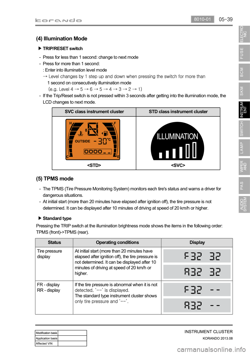
SVC class instrument cluster STD class instrument cluster
(4) Illumination Mode
TRIP/RESET switch
Press for less than 1 second: change to next mode
Press for more than 1 second:
: Enter into illumination level mode
1 second on consecutively illumination mode
If the Trip/Reset switch is not pressed within 3 seconds after getting into the illumination mode, the
LCD changes to next mode. -
-
-
(5) TPMS mode
The TPMS (Tire Pressure Monitoring System) monitors each tire's status and warns a driver for
dangerous situations.
At initial start (more than 20 minutes have elapsed after ignition off), the tire pressure is not
determined. It can be displayed after 10 minutes of driving at speed of 20 km/h or higher. -
-
Standard type
Pressing the TRIP switch at the illumination brightness mode shows the items in the following order:
TPMS (front)->TPMS (rear).
Status Operating conditions Display
Tire pressure
displayAt initial start (more than 20 minutes have
elapsed after ignition off), the tire pressure is
not determined. It can be displayed after 10
minutes of driving at speed of 20 km/h or
higher.
FR - display
RR - displayIf the tire pressure is abnormal when it is not
The standard type instrument cluster shows
Page 876 of 1336
8510-00
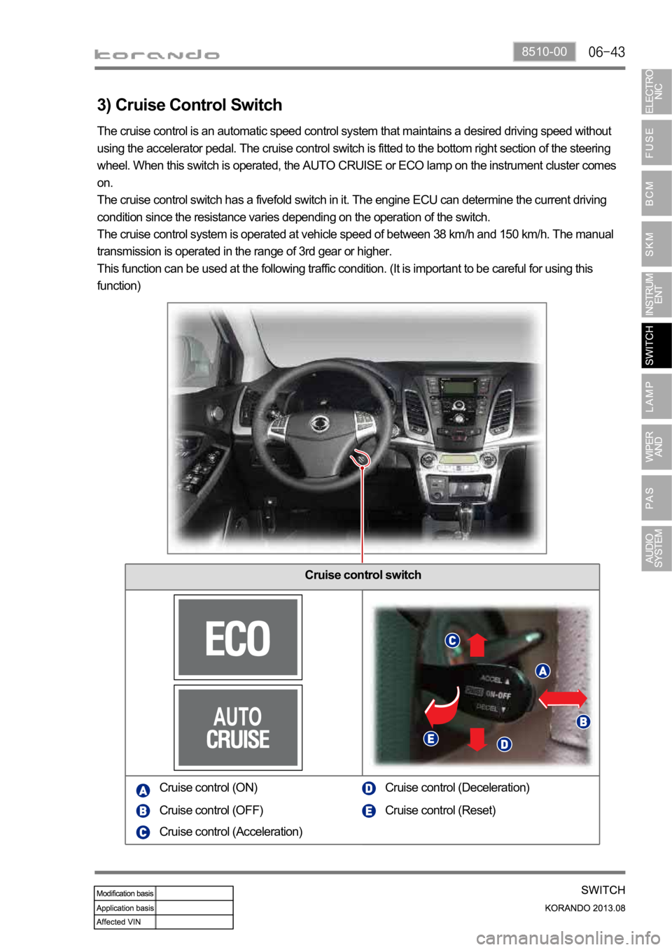
3) Cruise Control Switch
Cruise control switch
The cruise control is an automatic speed control system that maintains a desired driving speed without
using the accelerator pedal. The cruise control switch is fitted to the bottom right section of the steering
wheel. When this switch is operated, the AUTO CRUISE or ECO lamp on the instrument cluster comes
on.
The cruise control switch has a fivefold switch in it. The engine ECU can determine the current driving
condition since the resistance varies depending on the operation of the switch.
The cruise control system is operated at vehicle speed of between 38 km/h and 150 km/h. The manual
transmission is operated in the range of 3rd gear or higher.
This function can be used at the following traffic condition. (It is important to be careful for using this
function)
Cruise control (ON)
Cruise control (OFF)
Cruise control (Acceleration)Cruise control (Deceleration)
Cruise control (Reset)
Page 927 of 1336
7810-00
1. WIPER CONTROL
2. CAUTIONS ON RAIN SENSOR
When the wiper switch is in the AUTO position, the wiper will operate for 1 cycle if the initial engine
start is made. This may cause the wiper blades to wear prematurely. Therefore, other than rainy
days, set the switch to the OFF position. Especially during the winter time, check if the wiper blades
are not frozen to the windshield.
Operating the wiper with the blades frozen can damage the wiper motor.
If you operate the wipers when the windshield is dry without spraying washer fluid, the windshield
can be scratched and the wiper blades can wear prematurely. Use the wiper with the washer fluid
when the windshield is dry.
When it does not rain, turn the wiper switch to the OFF position.
Turn the wiper switch to the OFF position before any car wash to avoid unwanted operation of the
wipers. -
-
-
-Wiper mist & washer coupled wiper
Auto washer coupled wiper
Rain sensor coupled wiper operation (LIN)
Speed sensitive intermittent wiper
Wiper low/high control
Check if the sensor is off the position.
Check if the rain sensor cover is securely installed.
Check if the customer is familiar to how to control the wiper sensitivity.
Check if the wiper sensitivity control is set to the FAST side (step 5).
Check the wiper blade for wear.
If the wiper blade cannot wipe the glass uniformly and clearly, it may cause the rain sensor to work
irregularly. Therefore, in this case, replace the wiper blade with a new one. -
-
-
-
-Irregular operation (abrupt operation)
When cleaning the windshield over the sensor with damp clothes, the wiper may operate suddenly. It
could cause serious injury. Make sure to place the wiper switch to the OFF position and ignition switch
OFF when not in use.
Page 952 of 1336

Shift lever
IP display (SVC only)
sensors in the rear bumper detect the distance to any obstacle. The PAS detects the returning signals
reflected to the obstacles at regular intervals when the vehicle is parked to indicate the display and alarm
for the distance between the obstacles by phase so as to allow the driver easy parking by securing safe
distance.
1. OVERVIEW
Buzzer for PAS
Buzzer sounds using instrument
cluster buzzer
Rearview camera