sensor SSANGYONG KORANDO 2013 Workshop Manual
[x] Cancel search | Manufacturer: SSANGYONG, Model Year: 2013, Model line: KORANDO, Model: SSANGYONG KORANDO 2013Pages: 1336, PDF Size: 92.18 MB
Page 405 of 1336
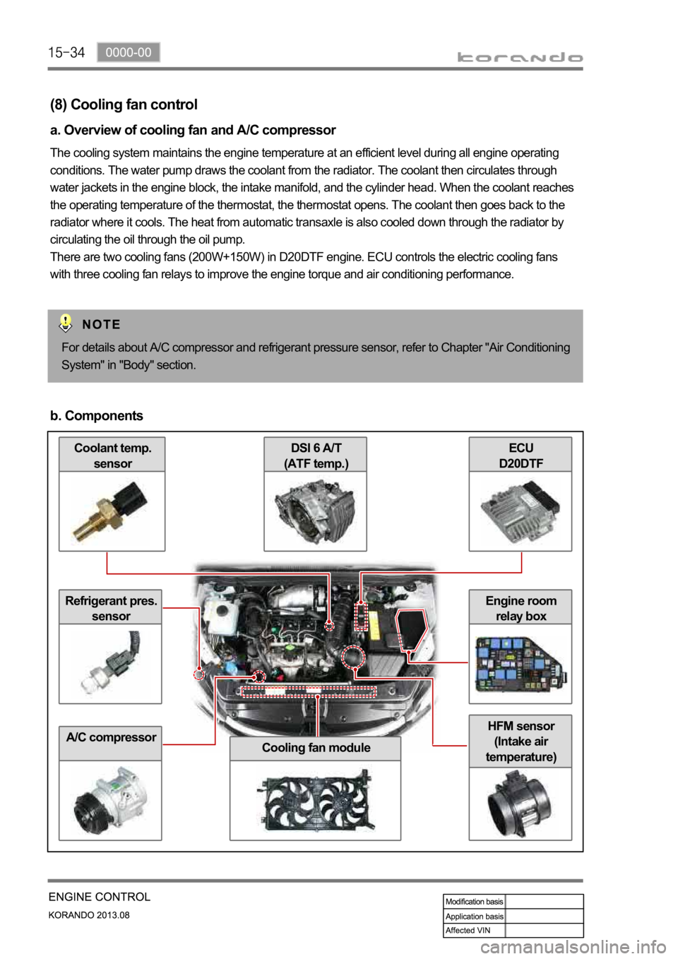
Coolant temp.
sensor
Refrigerant pres.
sensor
A/C compressor
ECU
D20DTFDSI 6 A/T
(ATF temp.)
Cooling fan module
HFM sensor
(Intake air
temperature)
Engine room
relay box
(8) Cooling fan control
a. Overview of cooling fan and A/C compressor
The cooling system maintains the engine temperature at an efficient level during all engine operating
conditions. The water pump draws the coolant from the radiator. The coolant then circulates through
water jackets in the engine block, the intake manifold, and the cylinder head. When the coolant reaches
the operating temperature of the thermostat, the thermostat opens. The coolant then goes back to the
radiator where it cools. The heat from automatic transaxle is also cooled down through the radiator by
circulating the oil through the oil pump.
There are two cooling fans (200W+150W) in D20DTF engine. ECU controls the electric cooling fans
with three cooling fan relays to improve the engine torque and air conditioning performance.
For details about A/C compressor and refrigerant pressure sensor, refer to Chapter "Air Conditioning
System" in "Body" section.
b. Components
Page 407 of 1336
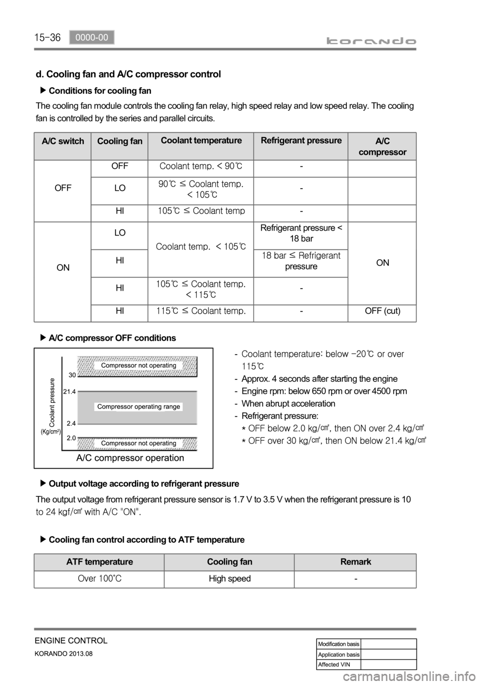
d. Cooling fan and A/C compressor control
Conditions for cooling fan
The cooling fan module controls the cooling fan relay, high speed relay and low speed relay. The cooling
fan is controlled by the series and parallel circuits.
A/C switch Cooling fanCoolant temperature Refrigerant pressure
A/C
compressor
OFF OFF
-
LO
-
HI
-
ONLO
Refrigerant pressure <
18 bar
ON HI
pressure
HI
-
HI
- OFF (cut)
A/C compressor OFF conditions
Approx. 4 seconds after starting the engine
Engine rpm: below 650 rpm or over 4500 rpm
When abrupt acceleration
Refrigerant pressure:
-
-
-
-
-
The output voltage from refrigerant pressure sensor is 1.7 V to 3.5 V when the refrigerant pressure is 10
Output voltage according to refrigerant pressure
Cooling fan control according to ATF temperature
ATF temperature Cooling fan Remark
High speed -
Page 408 of 1336
0000-00
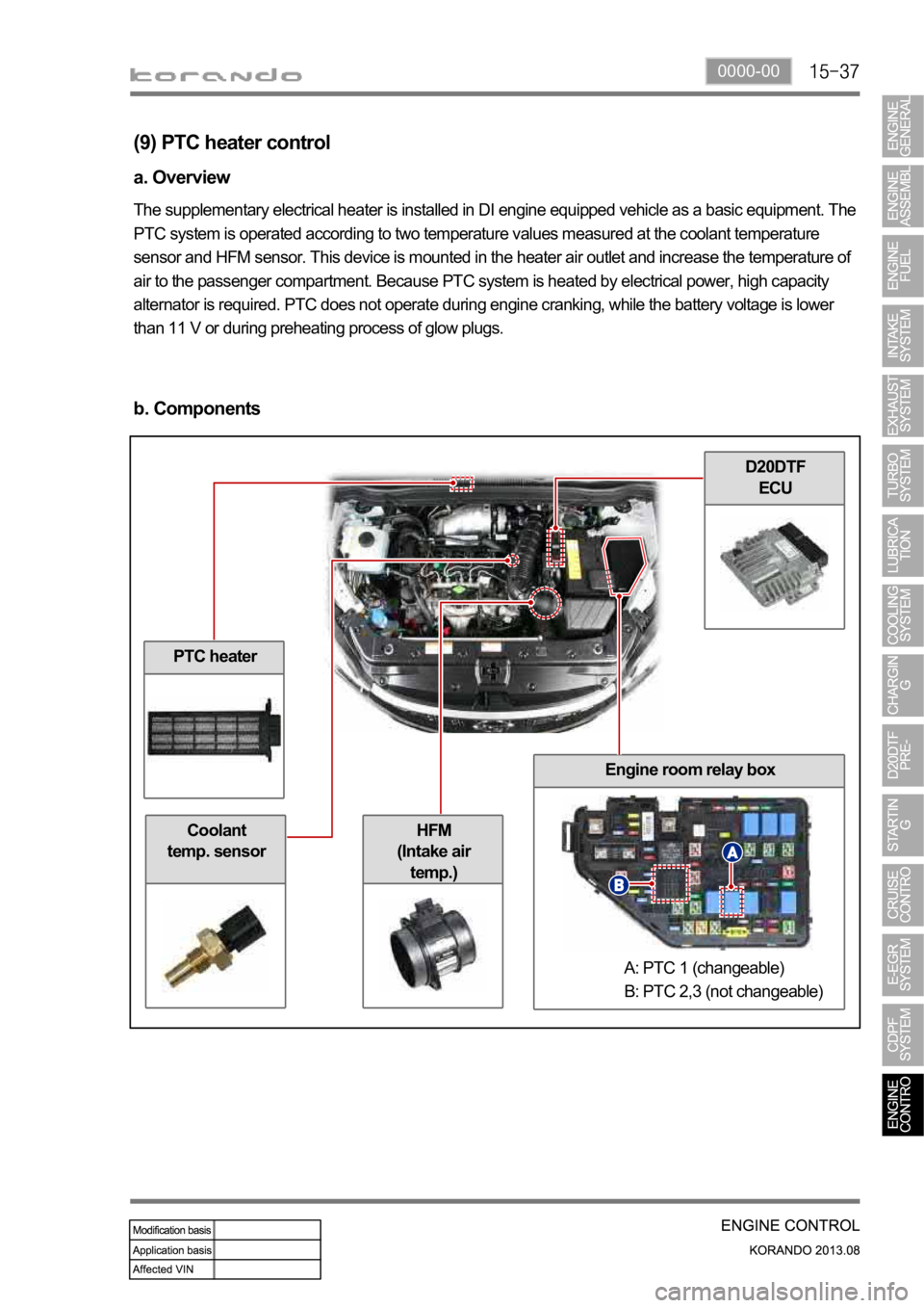
PTC heater
Coolant
temp. sensor
D20DTF
ECU
Engine room relay box
HFM
(Intake air
temp.)
(9) PTC heater control
a. Overview
The supplementary electrical heater is installed in DI engine equipped vehicle as a basic equipment. The
PTC system is operated according to two temperature values measured at the coolant temperature
sensor and HFM sensor. This device is mounted in the heater air outlet and increase the temperature of
air to the passenger compartment. Because PTC system is heated by electrical power, high capacity
alternator is required. PTC does not operate during engine cranking, while the battery voltage is lower
than 11 V or during preheating process of glow plugs.
b. Components
A: PTC 1 (changeable)
B: PTC 2,3 (not changeable)
Page 410 of 1336

0000-00
d. Control conditions
Operation Operating condition PTC Heater
HI
(PTC2)
PTC HI ON
LO
(PTC1)
PTC LO ON
Stop- A/C blower switch OFF
- Defective ambient air temperature sensor
(including open or short circuit)
- Engine cranking
- Low battery voltage (below 11V)
- During pre-glow process (glow indicator ON)
Operation diagram for PTC heater LO (step 2)
Page 415 of 1336

Rear temp.
sensor
Front temp.
sensorCDPF (DOC+DPF)
Throttle valveD20DTF ECUDifferential pres.
sensor
Oxygen sensor
(11) CDPF control
a. Overview
As the solution for environmental regulations and PM Particle Material) of diesel engine, the low emission
vehicle is getting popular. This vehicle is equipped with an extra filter to collect the soot and burn it again
so that the amount of PM in the exhaust gas passed through the DOC (Diesel Oxidation Catalyst) is
reduced. The CDPF (Catalyst & Diesel Particulate Filter) is an integrated filter including DOC (Diesel
Oxidation Catalyst) and DPF (Diesel Particulate Filter).
For details, refer to Chapter "CDPF".
b. Components
Page 417 of 1336

Rear temp. sensor:
Measure DPF
temp.DPF performs
recycling
(combustion)
process at 600C,
and rear
temperature sensor
monitors the
temperature of DPF.
Differential pressure
sensor measures the
pressure difference
between pre-CDPF
and post-CDPF (If
PM has been
accumulated, the
measured value is
over the specified
value).Diff. pres. sensor:
Measure
pressure between
front side and
rear side of CDPF
Injector: Control
post injection
Front temp.
sensor: Measure
DOC temp.DOC performs
oxidation and
reduction process at
front temperature
sensor monitors the
temperature of
DOC.
Electronic
throttle body:
Control intake ai
r
mass
ECU (DCM 3.7)
d. Operation process
When the differential pressure sensor detects the pressure difference between the front and the rear
side of CDPF, the sensor sends signal indicating the soot is accumulated and the post injection is
performed to raise the temperature of exhaust gas. The amount of fuel injected is determined according
to the temperature of exhaust gas detected by the rear temperature sensor. If the temperature is below
low load range, the amount of post injection and the amount of intake air are controlled. It is to raise the
temperature by increasing the amount of fuel while decreasing the amount of intake air.
T-MAP sensor
Intake air
mass
Exceed PM
limitBooster
pressure/
temperaturePost injection
Control intake air
mass
Page 423 of 1336
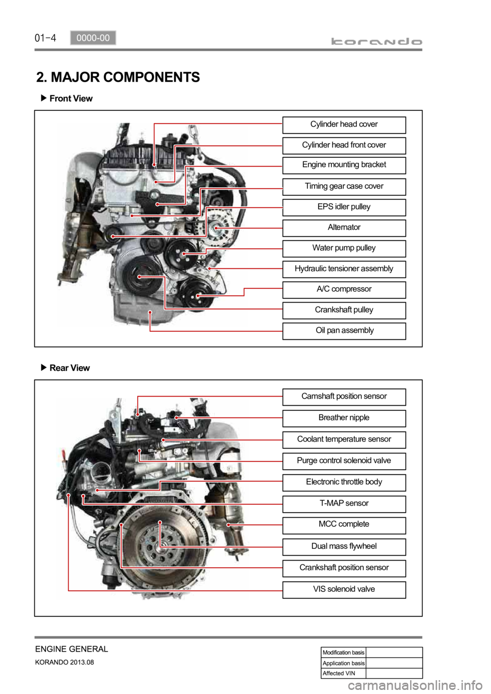
Engine mounting bracket
2. MAJOR COMPONENTS
Front View
Cylinder head front cover
Timing gear case cover
EPS idler pulley
Alternator
Water pump pulley
A/C compressor
Crankshaft pulley
Oil pan assembly
Rear View
Camshaft position sensor
Breather nipple
Purge control solenoid valveCoolant temperature sensor
Electronic throttle body
T-MAP sensor
MCC complete
VIS solenoid valve Cylinder head cover
Dual mass flywheel
Crankshaft position sensor
Hydraulic tensioner assembly
Page 424 of 1336
0000-00
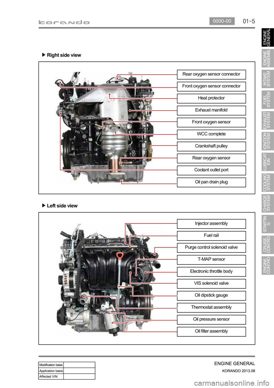
Right side view
Left side view
Rear oxygen sensor connector
Front oxygen sensor connector
Exhaust manifoldHeat protector
Front oxygen sensor
WCC complete
Crankshaft pulley
Oil pan drain plug
Rear oxygen sensor
Coolant outlet port
Injector assembly
Fuel rail
T-MAP sensor Purge control solenoid valve
Electronic throttle body
VIS solenoid valve
Oil dipstick gauge
Oil filter assembly
Thermostat assembly
Oil pressure sensor
Page 449 of 1336

Components
Exhaust camshaftOCVFinger follower & HLA
Intake camshaftIntake camshaft CVVT
gearCamshaft position
sensor
Page 470 of 1336
1128-01
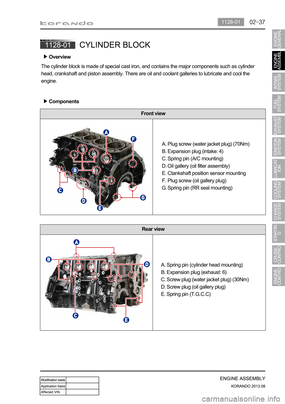
Front view
Rear view
Spring pin (cylinder head mounting)
Expansion plug (exhaust: 6)
Screw plug (water jacket plug) (30Nm)
Screw plug (oil gallery plug)
Spring pin (T.G.C.C) A.
B.
C.
D.
E.
Overview
The cylinder block is made of special cast iron, and contains the major components such as cylinder
head, crankshaft and piston assembly. There are oil and coolant galleries to lubricate and cool the
engine.
Components
Plug screw (water jacket plug) (70Nm)
Expansion plug (intake: 4)
Spring pin (A/C mounting)
Oil gallery (oil filter assembly)
Ctankshaft position sensor mounting
Plug screw (oil gallery plug)
Spring pin (RR seal mounting) A.
B.
C.
D.
E.
F.
G.