SSANGYONG KORANDO 2013 Service Manual
Manufacturer: SSANGYONG, Model Year: 2013, Model line: KORANDO, Model: SSANGYONG KORANDO 2013Pages: 1336, PDF Size: 92.18 MB
Page 371 of 1336
1114-00
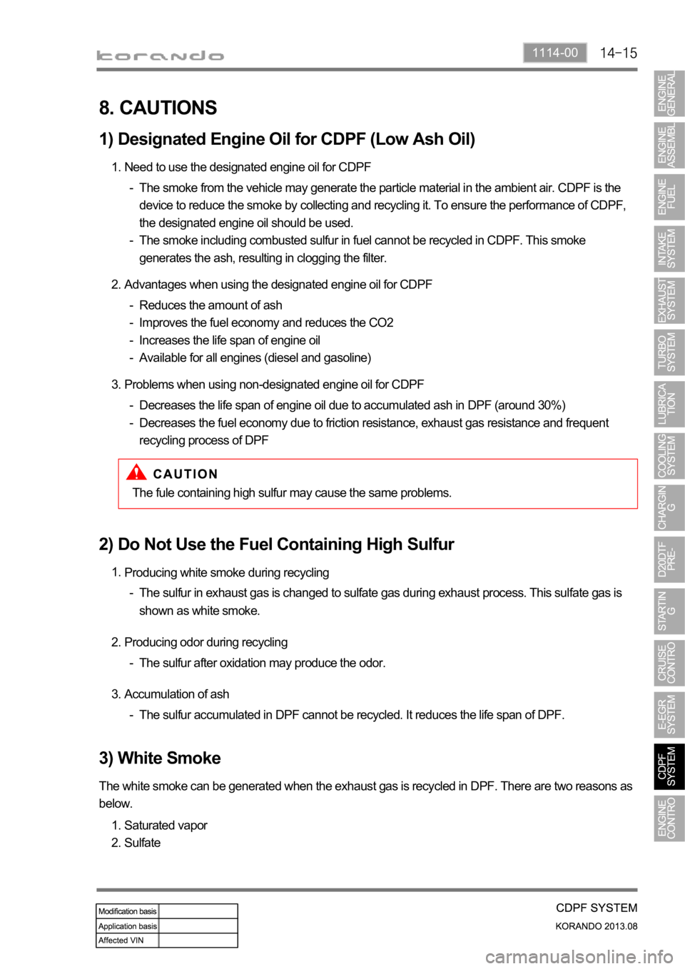
8. CAUTIONS
1) Designated Engine Oil for CDPF (Low Ash Oil)
Need to use the designated engine oil for CDPF 1.
The smoke from the vehicle may generate the particle material in the ambient air. CDPF is the
device to reduce the smoke by collecting and recycling it. To ensure the performance of CDPF,
the designated engine oil should be used.
The smoke including combusted sulfur in fuel cannot be recycled in CDPF. This smoke
generates the ash, resulting in clogging the filter. -
-
Advantages when using the designated engine oil for CDPF 2.
Reduces the amount of ash
Improves the fuel economy and reduces the CO2
Increases the life span of engine oil
Available for all engines (diesel and gasoline) -
-
-
-
Problems when using non-designated engine oil for CDPF 3.
Decreases the life span of engine oil due to accumulated ash in DPF (around 30%)
Decreases the fuel economy due to friction resistance, exhaust gas resistance and frequent
recycling process of DPF -
-
The fule containing high sulfur may cause the same problems.
2) Do Not Use the Fuel Containing High Sulfur
Producing white smoke during recycling 1.
The sulfur in exhaust gas is changed to sulfate gas during exhaust process. This sulfate gas is
shown as white smoke. -
Producing odor during recycling 2.
The sulfur after oxidation may produce the odor. -
Accumulation of ash 3.
The sulfur accumulated in DPF cannot be recycled. It reduces the life span of DPF. -
3) White Smoke
The white smoke can be generated when the exhaust gas is recycled in DPF. There are two reasons as
below.
Saturated vapor
Sulfate 1.
2.
Page 372 of 1336
![SSANGYONG KORANDO 2013 Service Manual No. Sensor item Data Unit Description
1 Driven distance from last
CDPF regeneration0 km
2 CDPF regeneration history
(distance/time) Index0 -
3 Driven distance between
CDPF regenerations[0]0 SSANGYONG KORANDO 2013 Service Manual No. Sensor item Data Unit Description
1 Driven distance from last
CDPF regeneration0 km
2 CDPF regeneration history
(distance/time) Index0 -
3 Driven distance between
CDPF regenerations[0]0](/img/67/57503/w960_57503-371.png)
No. Sensor item Data Unit Description
1 Driven distance from last
CDPF regeneration0 km
2 CDPF regeneration history
(distance/time) Index0 -
3 Driven distance between
CDPF regenerations[0]0 km
4 Driven distance between
CDPF regenerations[1]0 km
5 Driven distance between
CDPF regenerations[2]0 km
6 Driven distance between
CDPF regenerations[3]0 km
7 Driven distance between
CDPF regenerations[4]0 km
8 CDPF regeneration time[0] 0.0 S
9 CDPF regeneration time[2] 0.0 S
10 CDPF regeneration time[2] 0.0 S
11 CDPF regeneration time[3] 0.0 S
12 CDPF regeneration time[4] 0.0 S
13 CDPF regeneration history
(OK/Fail) Index0 -
14 CDPF regeneration history[0] OK OK/Fail
15 CDPF regeneration history[1] OK OK/Fail
16 CDPF regeneration history[2] OK OK/Fail
17 CDPF regeneration history[3] OK OK/Fail
18 CDPF regeneration history[4] OK OK/Fail
19 Times of CDPF regeneration
start (differential pressure)0 -
Driven distance from last generation up to
now
Display regeneration history (distance/time)
stored until now in figure, Index ([0] ~ [4])
The regeneration distance/time is stored up
to the last 5 events in sequence and the
oldest one will be deleted if the number of
events is exceeded 5 times.
The currently displayed index value indicates
where the regeneration information will be
stored in the future and the just previous
value shows the last regeneration
information.
Ex) Index value: 3 (last regeneration
information stored at 2)
Display regeneration history (OK/Fail) stored
until now in figure, Index ([0]~[4])
The regeneration distance/time is stored up
to the last 5 events in sequence and the
oldest one will be deleted if the number of
events is exceeded 5 times.
The currently displayed index value indicates
where the regeneration information will be
stored in the future and the just previous
value shows the last regeneration
information.
Ex) Index value: 3 (last regeneration
information stored at 2)
Times which regeneration is requested using
differential pressure sensor signal
9. DESCRIPTION ON CDPF REGENERATION
Page 373 of 1336
1114-00
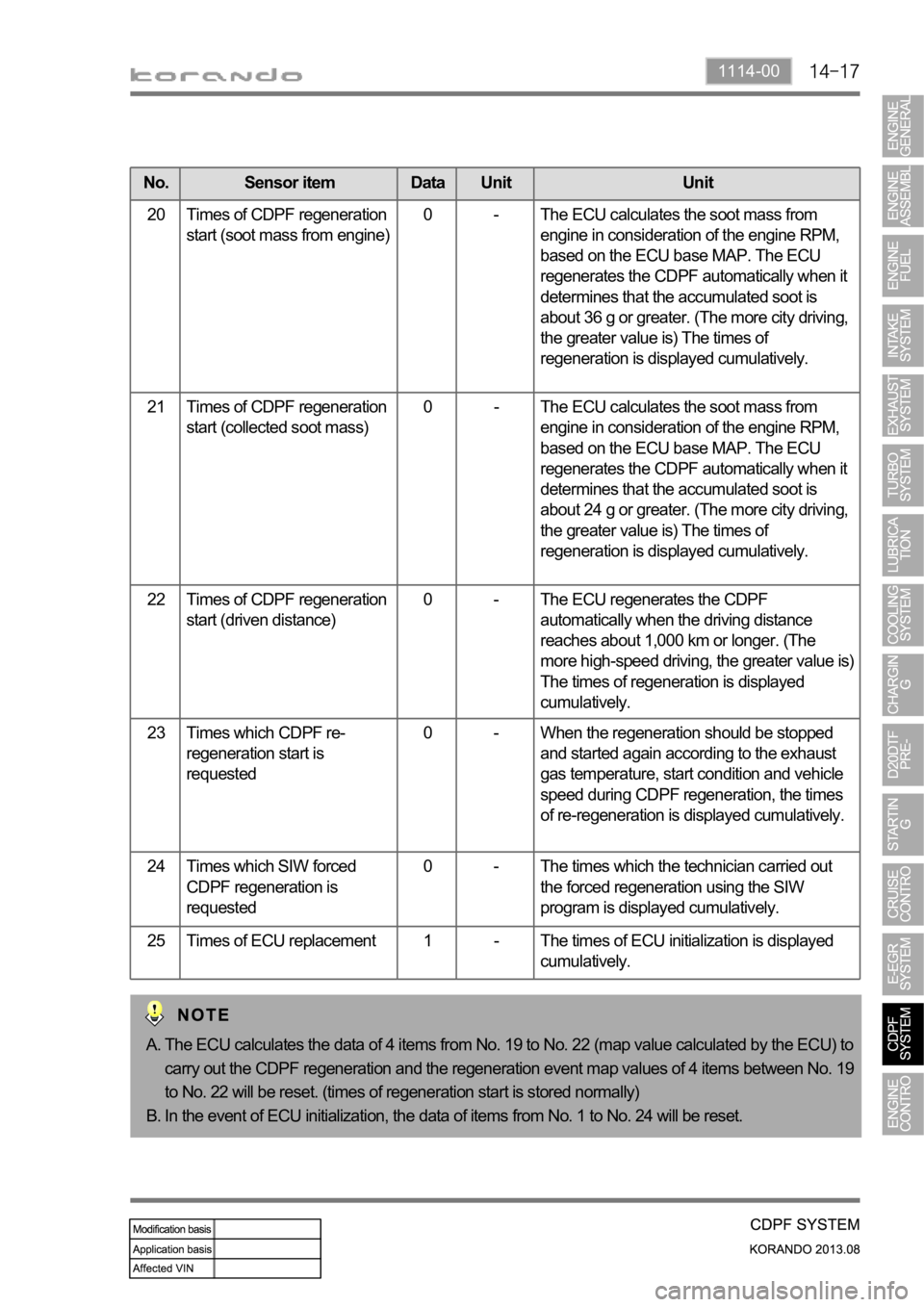
No. Sensor item Data Unit Unit
20 Times of CDPF regeneration
start (soot mass from engine)0 - The ECU calculates the soot mass from
engine in consideration of the engine RPM,
based on the ECU base MAP. The ECU
regenerates the CDPF automatically when it
determines that the accumulated soot is
about 36 g or greater. (The more city driving,
the greater value is) The times of
regeneration is displayed cumulatively.
21 Times of CDPF regeneration
start (collected soot mass)0 - The ECU calculates the soot mass from
engine in consideration of the engine RPM,
based on the ECU base MAP. The ECU
regenerates the CDPF automatically when it
determines that the accumulated soot is
about 24 g or greater. (The more city driving,
the greater value is) The times of
regeneration is displayed cumulatively.
22 Times of CDPF regeneration
start (driven distance)0 - The ECU regenerates the CDPF
automatically when the driving distance
reaches about 1,000 km or longer. (The
more high-speed driving, the greater value is)
The times of regeneration is displayed
cumulatively.
23 Times which CDPF re-
regeneration start is
requested0 - When the regeneration should be stopped
and started again according to the exhaust
gas temperature, start condition and vehicle
speed during CDPF regeneration, the times
of re-regeneration is displayed cumulatively.
24 Times which SIW forced
CDPF regeneration is
requested0 - The times which the technician carried out
the forced regeneration using the SIW
program is displayed cumulatively.
25 Times of ECU replacement 1 - The times of ECU initialization is displayed
cumulatively.
The ECU calculates the data of 4 items from No. 19 to No. 22 (map value calculated by the ECU) to
carry out the CDPF regeneration and the regeneration event map values of 4 items between No. 19
to No. 22 will be reset. (times of regeneration start is stored normally)
In the event of ECU initialization, the data of items from No. 1 to No. 24 will be reset. A.
B.
Page 374 of 1336
0000-00
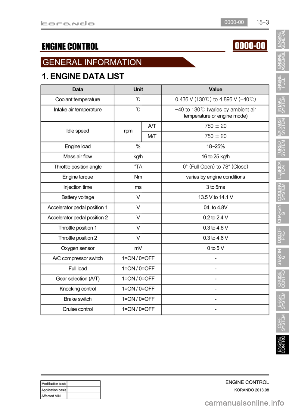
1. ENGINE DATA LIST
Data Unit Value
Coolant temperature
Intake air temperature
temperature or engine mode)
Idle speed rpmA/T
M/T
Engine load % 18~25%
Mass air flow kg/h 16 to 25 kg/h
Throttle position angle
Engine torque Nm varies by engine conditions
Injection time ms 3 to 5ms
Battery voltage V 13.5 V to 14.1 V
Accelerator pedal position 1 V 04. to 4.8V
Accelerator pedal position 2 V 0.2 to 2.4 V
Throttle position 1 V 0.3 to 4.6 V
Throttle position 2 V 0.3 to 4.6 V
Oxygen sensor mV 0 to 5 V
A/C compressor switch 1=ON / 0=OFF -
Full load 1=ON / 0=OFF -
Gear selection (A/T) 1=ON / 0=OFF -
Knocking control 1=ON / 0=OFF -
Brake switch 1=ON / 0=OFF -
Cruise control 1=ON / 0=OFF -
Page 375 of 1336
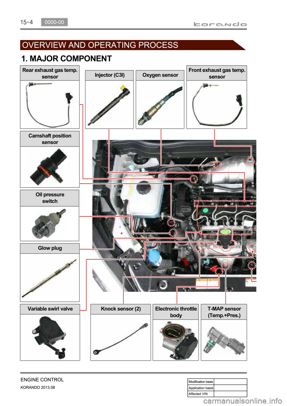
Variable swirl valveElectronic throttle
bodyT-MAP sensor
(Temp.+Pres.)
Injector (C3I)Oxygen sensorFront exhaust gas temp.
sensor
Glow plug
Knock sensor (2)
Oil pressure
switch
1. MAJOR COMPONENT
Rear exhaust gas temp.
sensor
Camshaft position
sensor
Page 376 of 1336
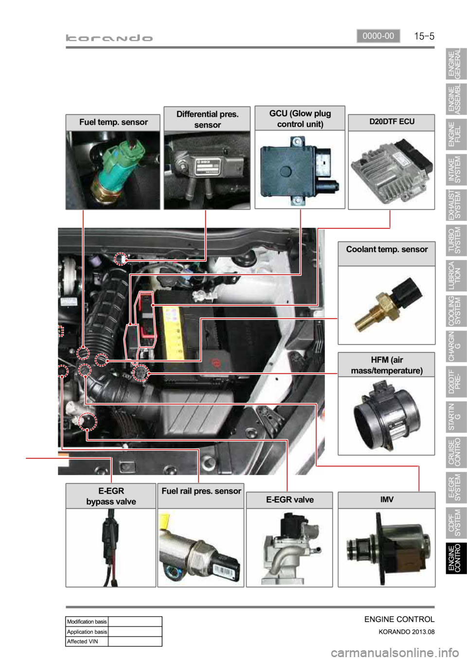
0000-00
Coolant temp. sensor
HFM (air
mass/temperature)
Fuel temp. sensorDifferential pres.
sensorD20DTF ECU
IMV
E-EGR
bypass valve
E-EGR valve
Fuel rail pres. sensor
GCU (Glow plug
control unit)
Page 377 of 1336
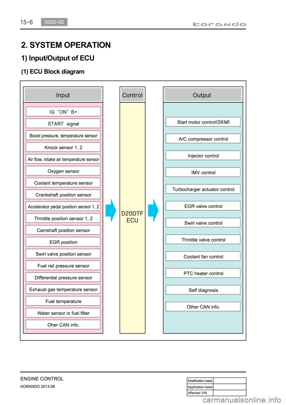
2. SYSTEM OPERATION
1) Input/Output of ECU
(1) ECU Block diagram
Page 378 of 1336
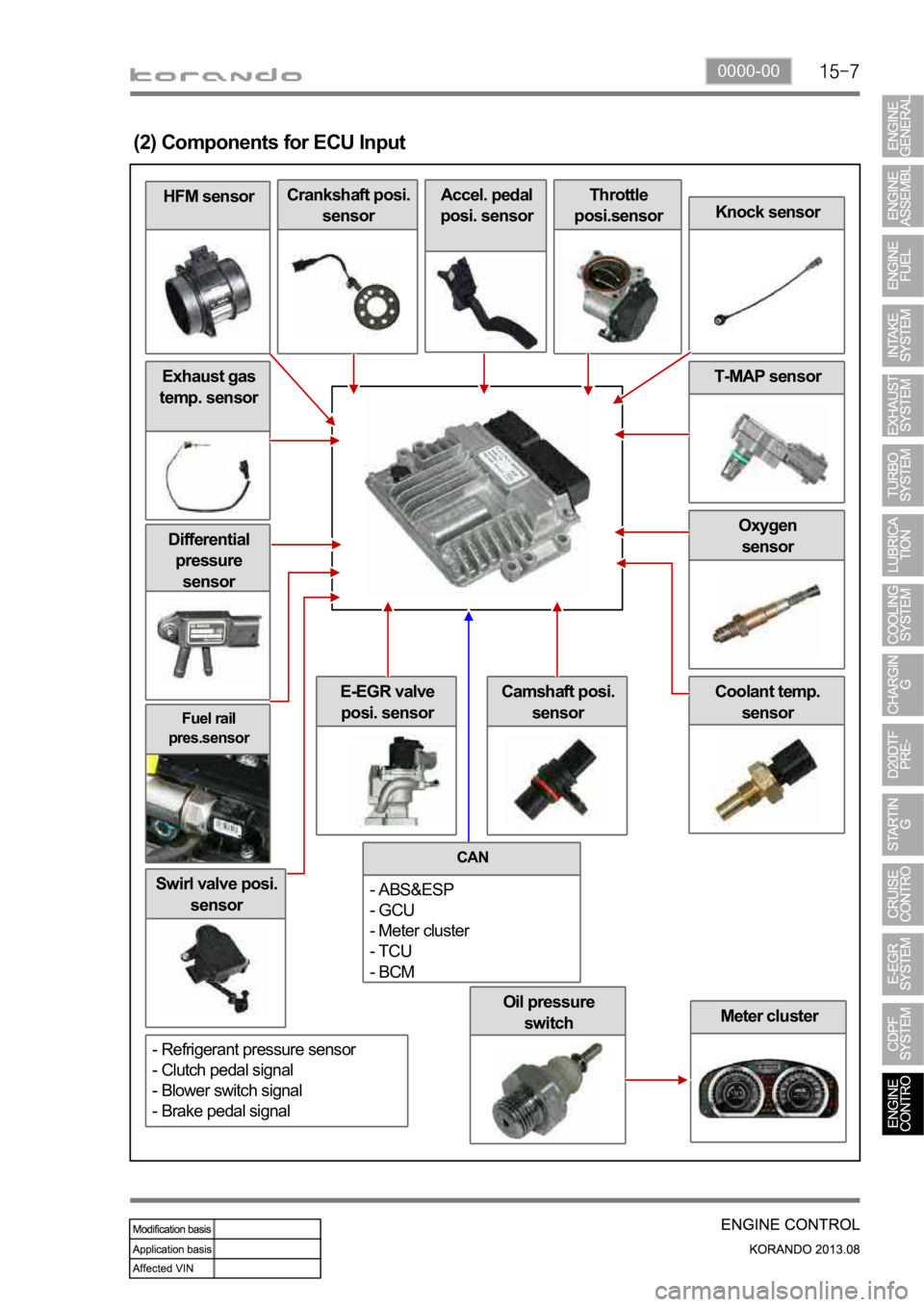
0000-00
Oil pressure
switch
Fuel rail
pres.sensor
Differential
pressure
sensor
Swirl valve posi.
sensor
Meter cluster
Coolant temp.
sensorE-EGR valve
posi. sensor
Oxygen
sensor
Exhaust gas
temp. sensor
HFM sensor
(2) Components for ECU Input
Crankshaft posi.
sensorAccel. pedal
posi. sensorThrottle
posi.sensor
Knock sensor
T-MAP sensor
Camshaft posi.
sensor
CAN
- ABS&ESP
- GCU
- Meter cluster
- TCU
- BCM
- Refrigerant pressure sensor
- Clutch pedal signal
- Blower switch signal
- Brake pedal signal
Page 379 of 1336
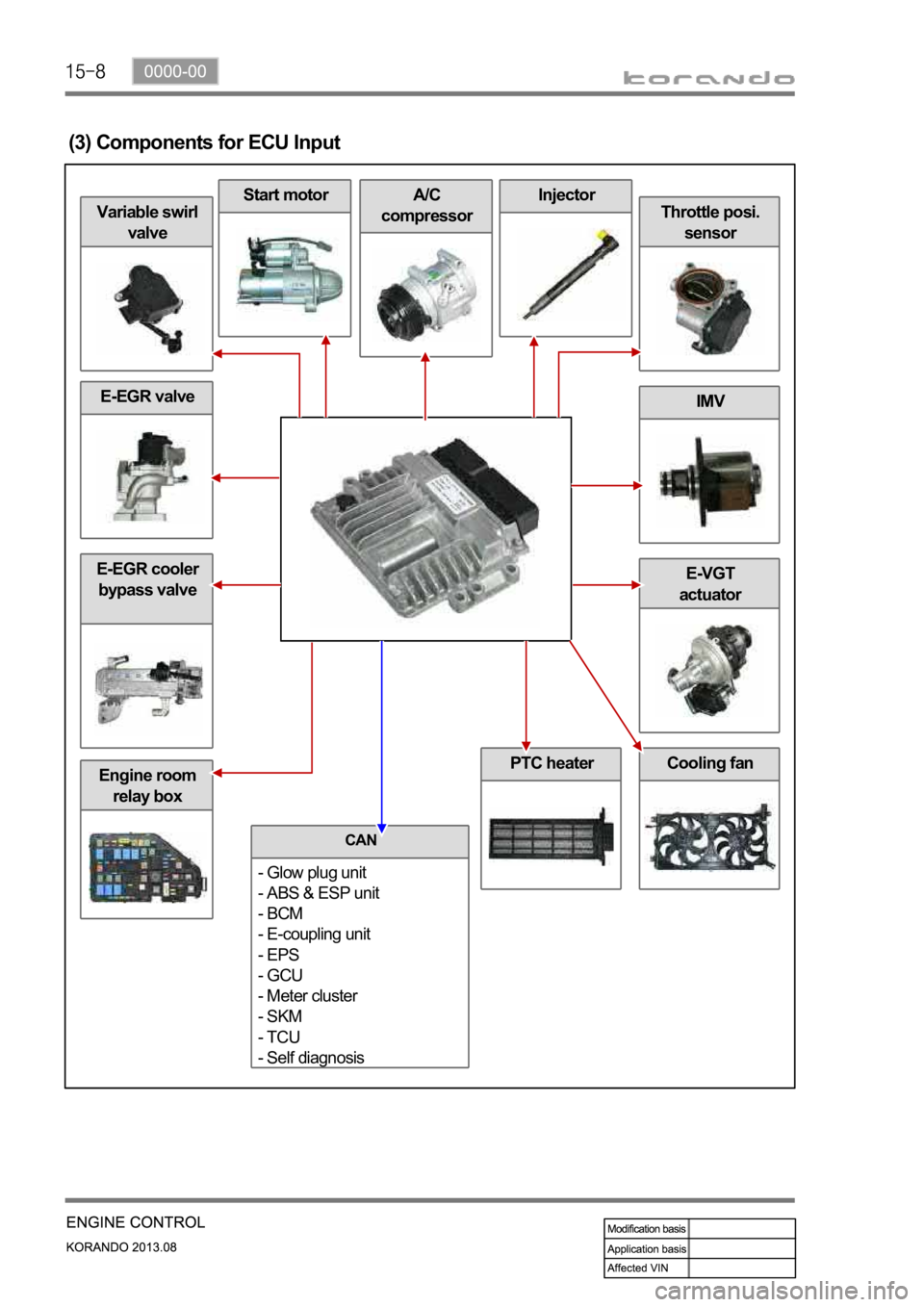
Engine room
relay box
E-EGR valve
Cooling fan
E-EGR cooler
bypass valveE-VGT
actuator
IMV
Throttle posi.
sensor
InjectorA/C
compressorStart motor
Variable swirl
valve
(3) Components for ECU Input
PTC heater
CAN
- Glow plug unit
- ABS & ESP unit
- BCM
- E-coupling unit
- EPS
- GCU
- Meter cluster
- SKM
- TCU
- Self diagnosis
Page 380 of 1336
0000-00
2) ECU Control
(1) Function
a. ECU Function
ECU receives and analyzes signals from various sensors and then modifies those signals into
permissible voltage levels and analyzes to control respective actuators.
ECU microprocessor calculates injection period and injection timing proper for engine piston speed and
crankshaft angle based on input data and stored specific map to control the engine power and emission
gas.
Output signal of the ECU microprocessor drives pressure control valve to control the rail pressure and
activates injector solenoid valve to control the fuel injection period and injection timing; so controls
various actuators in response to engine changes. Auxiliary function of ECU has adopted to reduce
emission gas, improve fuel economy and enhance safety, comforts and conveniences. For example,
there are EGR, booster pressure control, autocruise (export only) and immobilizer and adopted CAN
communication to exchange data among electrical systems (automatic T/M and brake system) in the
vehicle fluently. And Scanner can be used to diagnose vehicle status and defectives.
water and electromagnetism and there should be no mechanical shocks.
To control the fuel volume precisely under repeated injections, high current should be applied instantly
so there is injector drive circuit in the ECU to generate necessary current during injector drive stages.
Current control circuit divides current applying time (injection time) into full-in-current-phase and hold-
current-phase and then the injectors should work very correctly under every working condition.
b. Control Function
Controls by operating stages
To make optimum combustion under every operating stage, ECU should calculate proper injection
volume in each stage by considering various factors.
Starting injection volume control
During initial starting, injecting fuel volume will be calculated by function of temperature and engine
cranking speed. Starting injection continues from when the ignition switch is turned to ignition
position to till the engine reaches to allowable minimum speed.
Driving mode control
If the vehicle runs normally, fuel injection volume will be calculated by accelerator pedal travel and
engine rpm and the drive map will be used to match the drivers inputs with optimum engine power. -
-
-