ESP SSANGYONG KORANDO 2013 Owner's Guide
[x] Cancel search | Manufacturer: SSANGYONG, Model Year: 2013, Model line: KORANDO, Model: SSANGYONG KORANDO 2013Pages: 1336, PDF Size: 92.18 MB
Page 548 of 1336

8530-00
2. CONFIGURATION
1) Circuit Diagram
The engine ECU detects the operating conditions of cruise control system, and monitors the braking
performance, vehicle speed, road conditions and ESP system operation. If the engine ECU determines
that there are not any problem to drive in cruise control mode, the vehicle can be operated by cruise
switch signals (decelerating, accelerating, cruising).
Page 555 of 1336
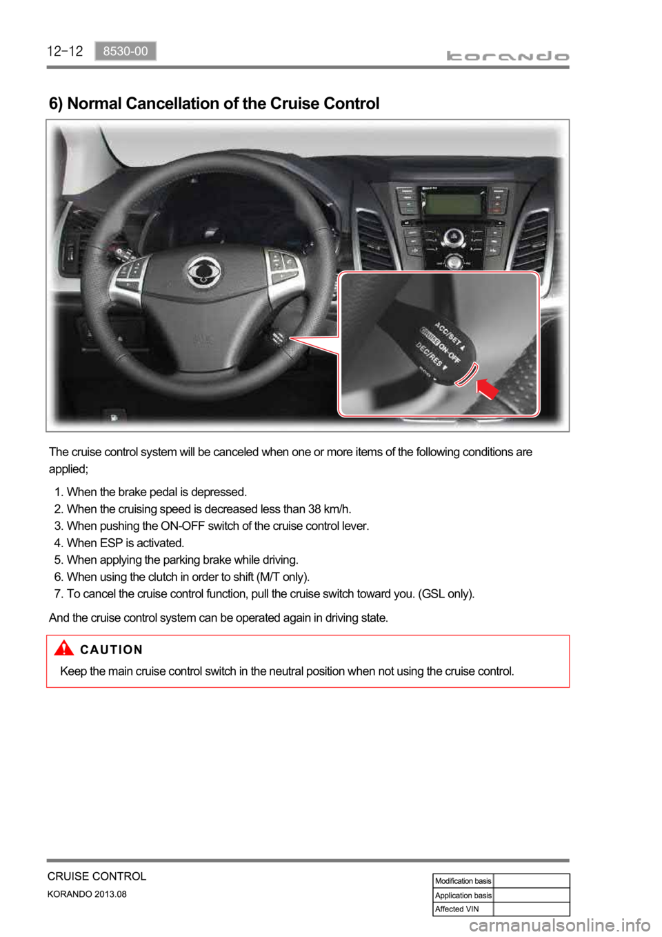
6) Normal Cancellation of the Cruise Control
The cruise control system will be canceled when one or more items of the following conditions are
applied;
When the brake pedal is depressed.
When the cruising speed is decreased less than 38 km/h.
When pushing the ON-OFF switch of the cruise control lever.
When ESP is activated.
When applying the parking brake while driving.
When using the clutch in order to shift (M/T only).
To cancel the cruise control function, pull the cruise switch toward you. (GSL only). 1.
2.
3.
4.
5.
6.
7.
Keep the main cruise control switch in the neutral position when not using the cruise control. And the cruise control system can be operated again in driving state.
Page 561 of 1336
0000-00
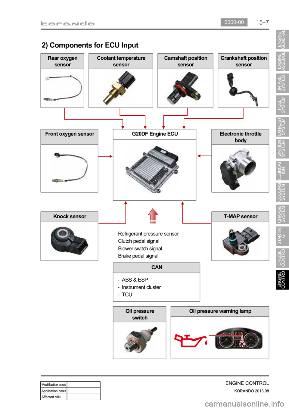
Rear oxygen
sensor
2) Components for ECU Input
Coolant temperature
sensorCamshaft position
sensorCrankshaft position
sensor
Front oxygen sensor
Knock sensor
G20DF Engine ECUElectronic throttle
body
Refrigerant pressure sensor
Clutch pedal signal
Blower switch signal
Brake pedal signal
CAN
ABS & ESP
Instrument cluster
TCU -
-
-
Oil pressure
switchOil pressure warning lamp
T-MAP sensor
Page 562 of 1336
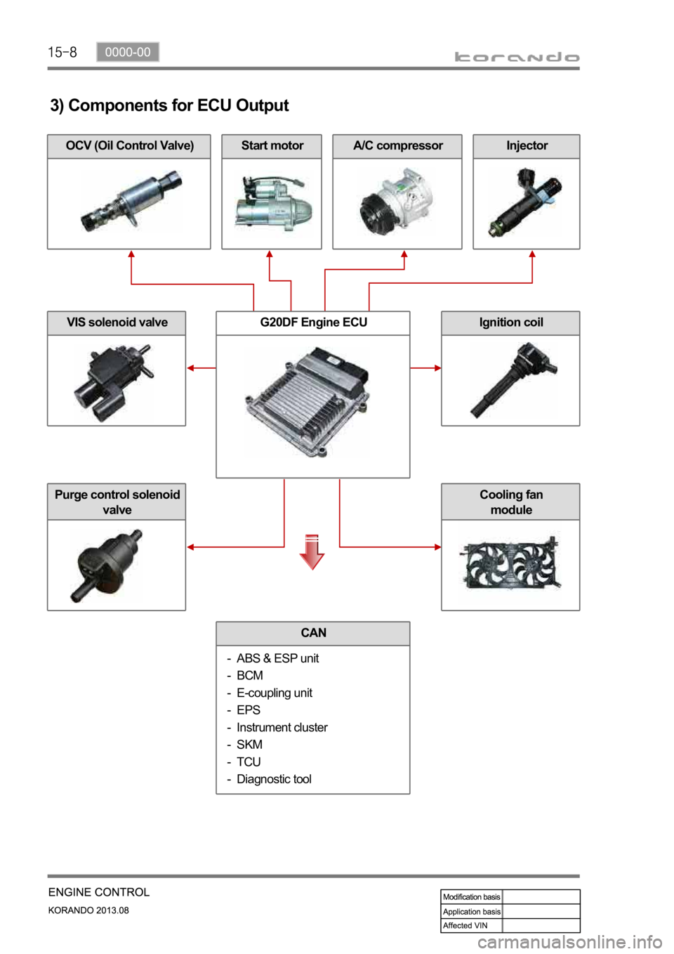
A/C compressorOCV (Oil Control Valve)
3) Components for ECU Output
Start motorInjector
VIS solenoid valve
Purge control solenoid
valve
G20DF Engine ECUIgnition coil
CAN
ABS & ESP unit
BCM
E-coupling unit
EPS
Instrument cluster
SKM
TCU
Diagnostic tool -
-
-
-
-
-
-
-
Cooling fan
module
Page 563 of 1336
1490-00
3. ECU CONTROL
1) Functions
ECU receives and analyzes signals from various sensors and then modifies those signals into
permissible voltage levels and analyzes to control respective actuators.
ECU microprocessor calculates injection period and injection timing proper for engine piston speed and
crankshaft angle based on input data and stored specific map to control the engine power and emission
gas.
Output signal of the ECU microprocessor activates the injector solenoid valve to control the fuel injection
period and injection timing; so controls various actuators in response to engine changes.
Auxiliary function of ECU has adopted to reduce emission gas, improve fuel economy and enhance
safety, comforts and conveniences. For example, there are autocruise and immobilizer and adopted
CAN communication to exchange data among electrical systems (automatic T/M and brake system) in
the vehicle fluently. And the diagnostic tool can be used to diagnose vehicle status and defectives.
water and electromagnetism and there should be no mechanical shocks.
2) Control Functions
Controls by operating stages:
To make optimum combustion under every operating stage, ECU should calculate proper injection
volume in each stage by considering various factors.
Starting injection volume control:
During initial starting, injecting fuel volume will be calculated by function of temperature and engine
cranking speed. Starting injection continues from when the ignition switch is turned to ignition
position to till the engine reaches to allowable minimum speed.
Driving mode control:
If the vehicle runs normally, fuel injection volume will be calculated by accelerator pedal travel and
engine rpm and the drive map will be used to match the drivers inputs with optimum engine power. -
-
-
Page 569 of 1336
0000-00
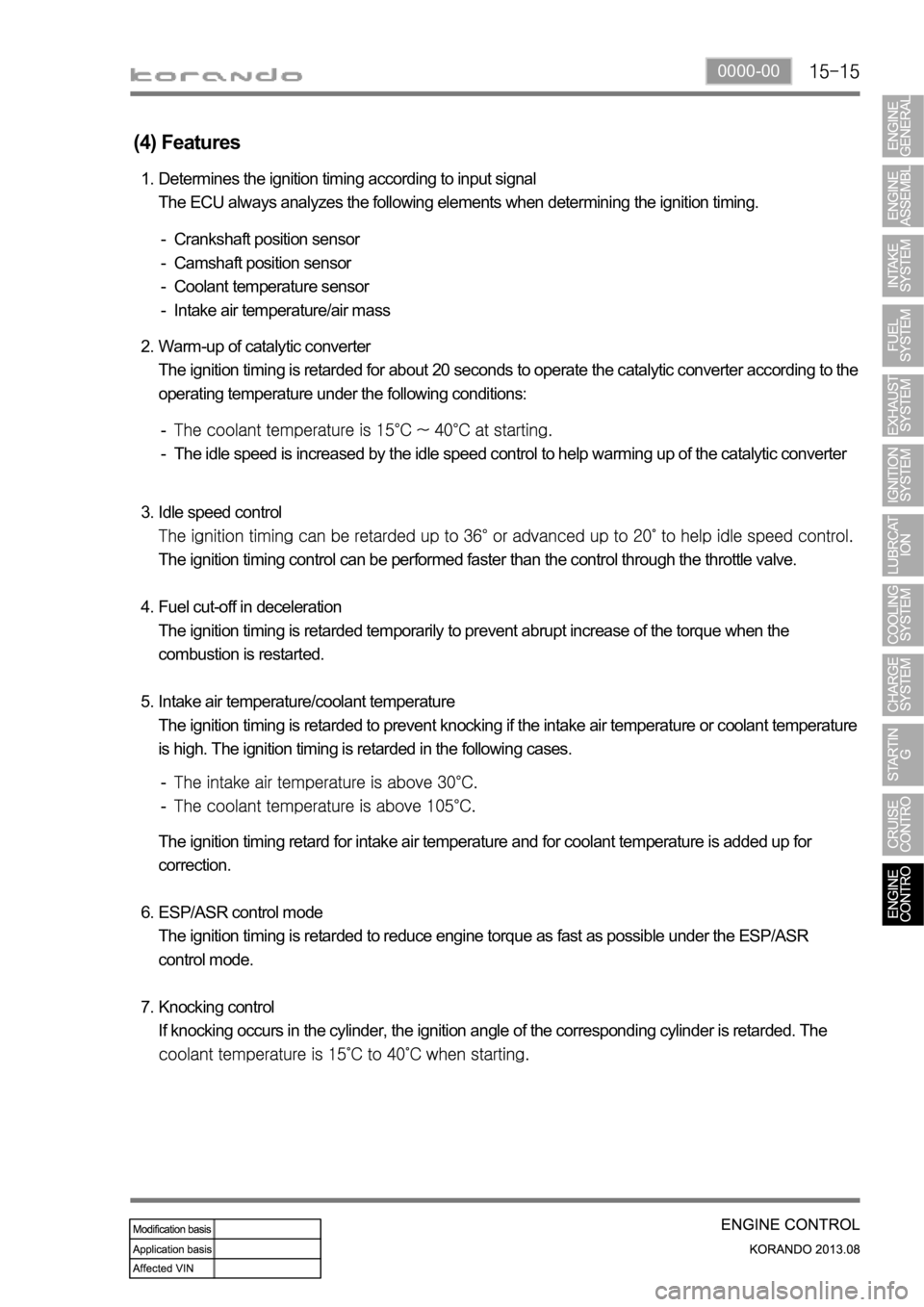
(4) Features
Determines the ignition timing according to input signal
The ECU always analyzes the following elements when determining the ignition timing. 1.
Crankshaft position sensor
Camshaft position sensor
Coolant temperature sensor
Intake air temperature/air mass -
-
-
-
Warm-up of catalytic converter
The ignition timing is retarded for about 20 seconds to operate the catalytic converter according to the
operating temperature under the following conditions: 2.
The idle speed is increased by the idle speed control to help warming up of the catalytic converter -
-
Idle speed control
The ignition timing control can be performed faster than the control through the throttle valve.
Fuel cut-off in deceleration
The ignition timing is retarded temporarily to prevent abrupt increase of the torque when the
combustion is restarted.
Intake air temperature/coolant temperature
The ignition timing is retarded to prevent knocking if the intake air temperature or coolant temperature
is high. The ignition timing is retarded in the following cases. 3.
4.
5.
-
-
The ignition timing retard for intake air temperature and for coolant temperature is added up for
correction.
ESP/ASR control mode
The ignition timing is retarded to reduce engine torque as fast as possible under the ESP/ASR
control mode.
Knocking control
If knocking occurs in the cylinder, the ignition angle of the corresponding cylinder is retarded. The
6.
7.
Page 577 of 1336
0000-00
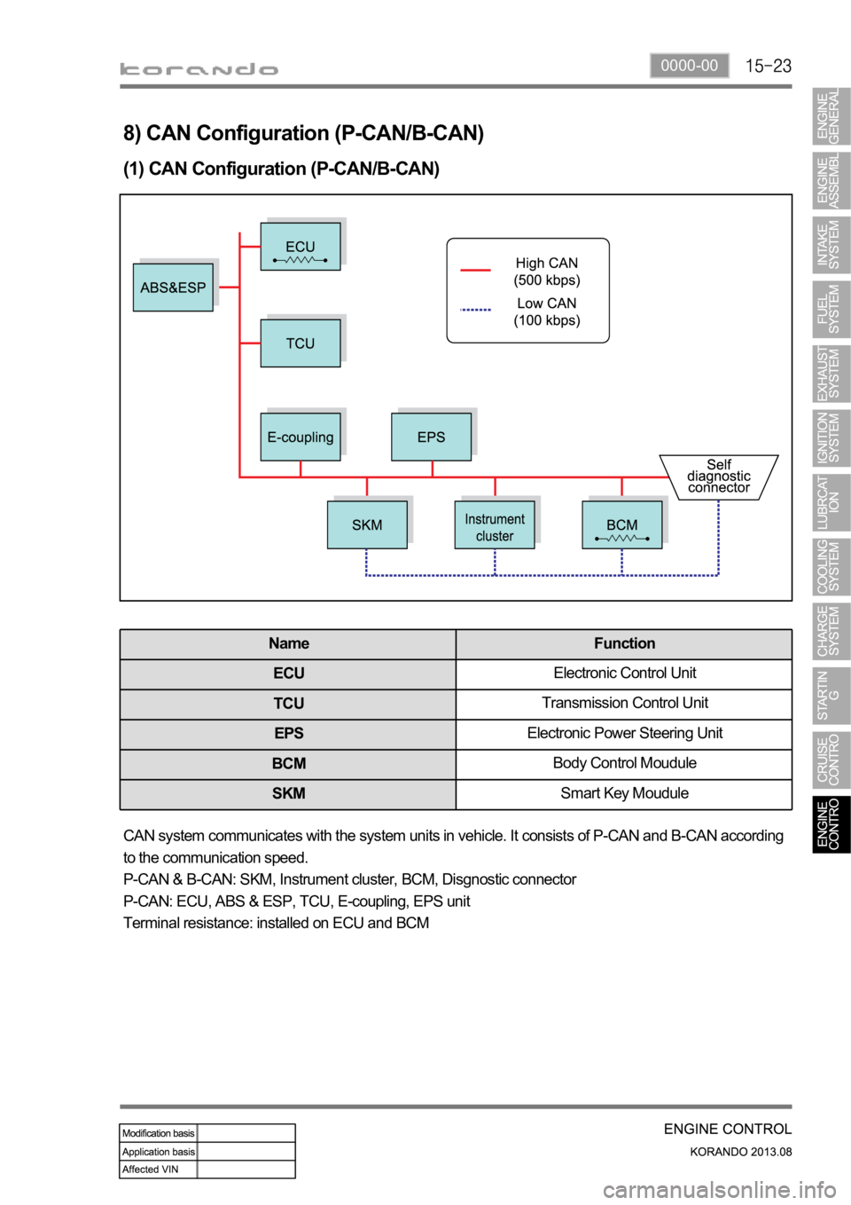
8) CAN Configuration (P-CAN/B-CAN)
(1) CAN Configuration (P-CAN/B-CAN)
Name Function
ECUElectronic Control Unit
TCUTransmission Control Unit
EPSElectronic Power Steering Unit
BCMBody Control Moudule
SKMSmart Key Moudule
CAN system communicates with the system units in vehicle. It consists of P-CAN and B-CAN according
to the communication speed.
P-CAN & B-CAN: SKM, Instrument cluster, BCM, Disgnostic connector
P-CAN: ECU, ABS & ESP, TCU, E-coupling, EPS unit
Terminal resistance: installed on ECU and BCM
Page 641 of 1336
8710-01
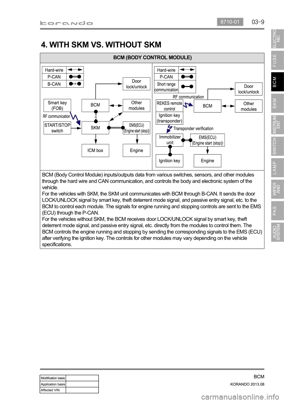
4. WITH SKM VS. WITHOUT SKM
BCM (BODY CONTROL MODULE)
BCM (Body Control Module) inputs/outputs data from various switches, sensors, and other modules
through the hard wire and CAN communication, and controls the body and electronic system of the
vehicle.
For the vehicles with SKM, the SKM unit communicates with BCM through B-CAN. It sends the door
LOCK/UNLOCK signal by smart key, theft deterrent mode signal, and passive entry signal, etc. to the
BCM to control each module. The signals for engine running and stopping controls are sent to the EMS
(ECU) through the P-CAN.
For the vehicles without SKM, the BCM receives door LOCK/UNLOCK signal by smart key, theft
deterrent mode signal, and passive entry signal, etc. directly from the modules to control them. The
BCM controls the engine running and stopping by sending the corresponding signals to the EMS (ECU)
after verifying the ignition key. The controls for other modules may vary depending on the vehicle
specifications.
Page 665 of 1336

8710-01
Abnormal wiper parking signal stop (GND)
The wiper system sends the corresponding signal of current status with IGN ON and wiper AUTO
switch ON. (The wiper motor is operated only when the request signal from the rain sensor is
received.) A. Operation 1. (When the wiper motor parking signal stopped at GND)
Abnormal wiper parking signal stop (IGN)
The wiper system sends the corresponding signal of current status for 2 seconds (T2) with IGN ON
and wiper AUTO switch ON.
After the 2 seconds (T2), the system outputs the signal of the stopped status.
(The wiper motor is operated only when the request signal from the rain sensor is received.) A.
B. Operation 1. (When the wiper motor parking signal stopped at ING)
Page 671 of 1336
8710-01
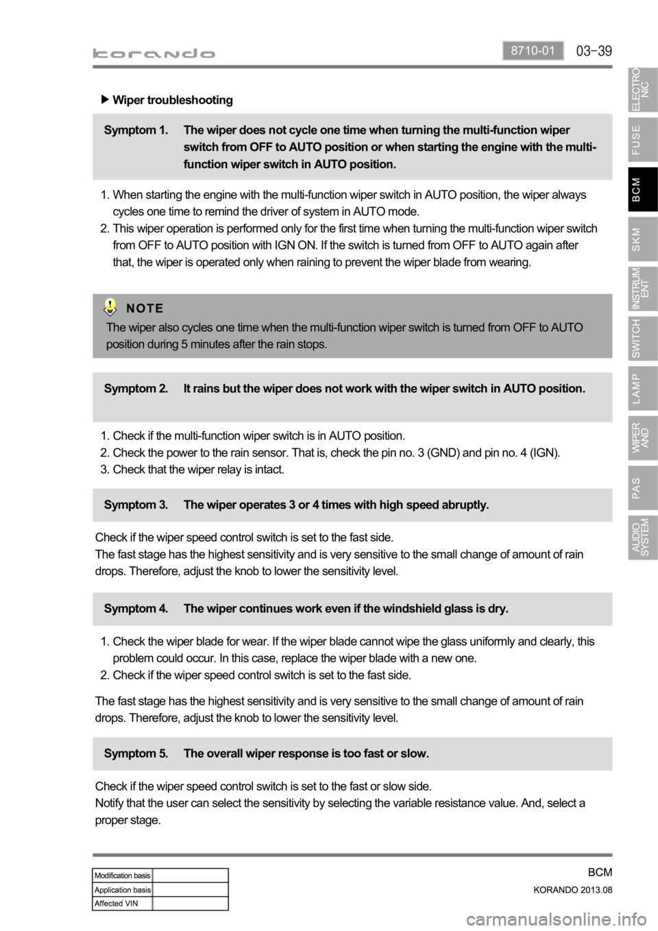
Wiper troubleshooting
The wiper does not cycle one time when turning the multi-function wiper
switch from OFF to AUTO position or when starting the engine with the multi-
function wiper switch in AUTO position. Symptom 1.
When starting the engine with the multi-function wiper switch in AUTO position, the wiper always
cycles one time to remind the driver of system in AUTO mode.
This wiper operation is performed only for the first time when turning the multi-function wiper switch
from OFF to AUTO position with IGN ON. If the switch is turned from OFF to AUTO again after
that, the wiper is operated only when raining to prevent the wiper blade from wearing. 1.
2.
It rains but the wiper does not work with the wiper switch in AUTO position. Symptom 2.
Check if the multi-function wiper switch is in AUTO position.
Check the power to the rain sensor. That is, check the pin no. 3 (GND) and pin no. 4 (IGN).
Check that the wiper relay is intact. 1.
2.
3.
The wiper operates 3 or 4 times with high speed abruptly. Symptom 3.
Check if the wiper speed control switch is set to the fast side.
The fast stage has the highest sensitivity and is very sensitive to the small change of amount of rain
drops. Therefore, adjust the knob to lower the sensitivity level.
The wiper continues work even if the windshield glass is dry. Symptom 4.
Check the wiper blade for wear. If the wiper blade cannot wipe the glass uniformly and clearly, this
problem could occur. In this case, replace the wiper blade with a new one.
Check if the wiper speed control switch is set to the fast side. 1.
2.
The fast stage has the highest sensitivity and is very sensitive to the small change of amount of rain
drops. Therefore, adjust the knob to lower the sensitivity level.
The overall wiper response is too fast or slow. Symptom 5.
Check if the wiper speed control switch is set to the fast or slow side.
Notify that the user can select the sensitivity by selecting the variable resistance value. And, select a
proper stage.The wiper also cycles one time when the multi-function wiper switch is turned from OFF to AUTO
position during 5 minutes after the rain stops.