battery SSANGYONG KORANDO 2013 Repair Manual
[x] Cancel search | Manufacturer: SSANGYONG, Model Year: 2013, Model line: KORANDO, Model: SSANGYONG KORANDO 2013Pages: 1336, PDF Size: 92.18 MB
Page 784 of 1336
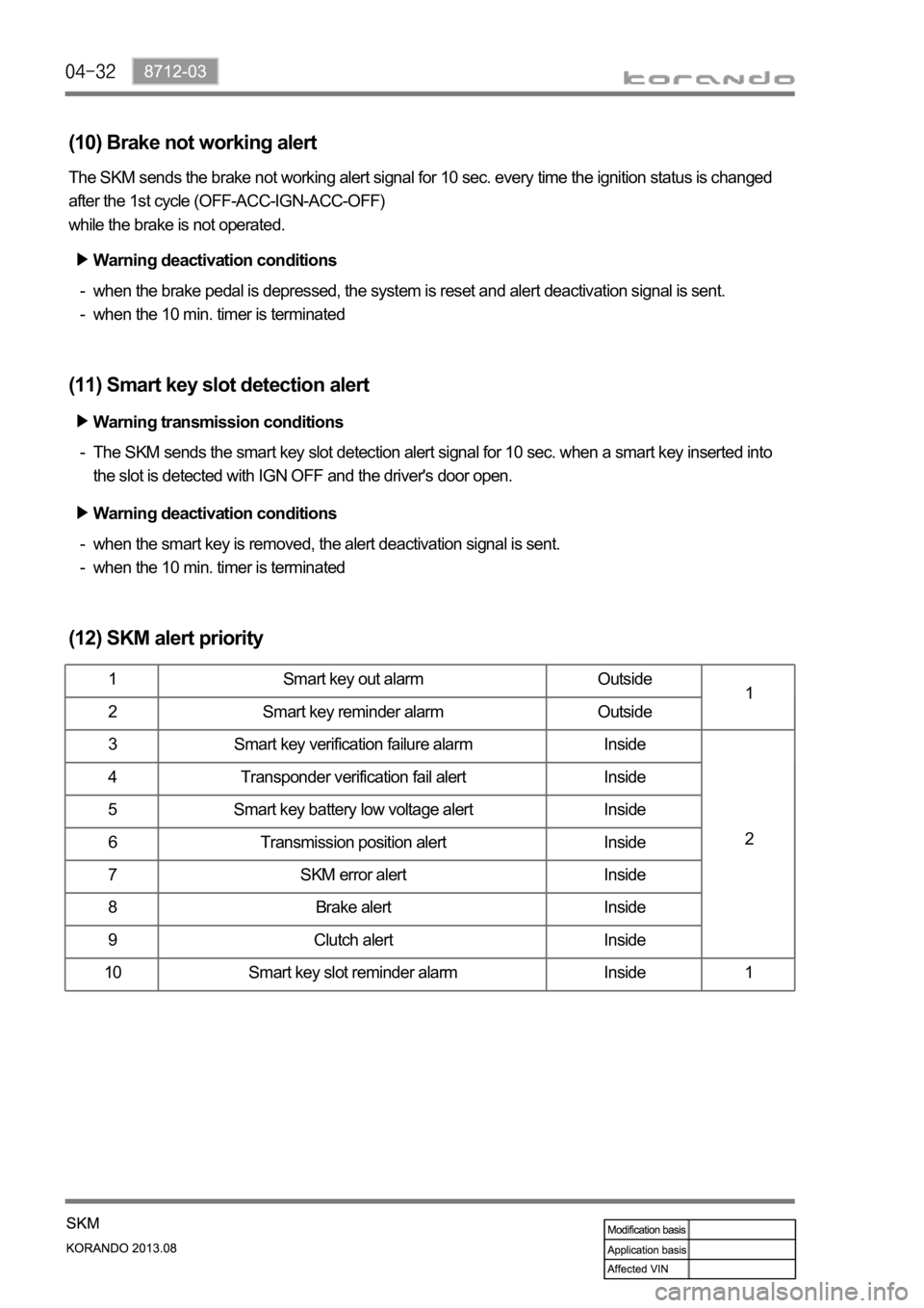
(10) Brake not working alert
The SKM sends the brake not working alert signal for 10 sec. every time the ignition status is changed
after the 1st cycle (OFF-ACC-IGN-ACC-OFF)
while the brake is not operated.
when the brake pedal is depressed, the system is reset and alert deactivation signal is sent.
when the 10 min. timer is terminated -
-
(11) Smart key slot detection alert
The SKM sends the smart key slot detection alert signal for 10 sec. when a smart key inserted into
the slot is detected with IGN OFF and the driver's door open. -
(12) SKM alert priority
1 Smart key out alarm Outside
1
2 Smart key reminder alarm Outside
3 Smart key verification failure alarm Inside
2 4 Transponder verification fail alert Inside
5 Smart key battery low voltage alert Inside
6 Transmission position alert Inside
7 SKM error alert Inside
8 Brake alert Inside
9 Clutch alert Inside
10 Smart key slot reminder alarm Inside 1
Warning deactivation conditions
Warning transmission conditions
Warning deactivation conditions
when the smart key is removed, the alert deactivation signal is sent.
when the 10 min. timer is terminated -
-
Page 785 of 1336

8712-03
Start motor
12. SKM IMMOBILIZER SYSTEM
1) System Description
The immobilizer system prevents the vehicle theft by allowing only the authorized key to start the engine.
The transponder inside the key communicates with the SKM (immobilizer slot) and EMS (ECU) through
P-CAN communication, and the system permits the engine to start after confirming the encrypted
coding.
When the START/STOP switch is pressed with the smart key inserted into the immobilizer slot because
of the smart key battery discharge, the SKM communicates with the EMS (ECU) through P-CAN, and
the ECU starts to control the engine only the signal is valid.
A valid key verification time is provided for 10 seconds and the engine can be started during this time. If
pressing the START/STOP switch again after this 10 seconds, the key verification process is performed
again.
2) Configuration
Emergency slot
Smart key
SKM
EMS (ECU)
Page 799 of 1336

8010-01
Indicator
(amber)
ESP
ESP OFF indicator
Engine check warning lamp
Indicator
(amber)
Indicator
(amber)
Indicator (red)
Battery charge warning lamp
Indicator (red)
Engine oil level warning lamp
This lamp comes on if any sensor or device related to the engine control is
defective.
This lamp comes on when the start switch is ON or when the battery level is
low.
(For EEM, warning lamp is controlled according to CAN signal)
This lamp comes on when the ignition switch is turned to "ON" position,
and then goes off if the engine oil level is normal.
If the engine oil level warning lamp comes on while driving, check the
engine oil level and oil leakage. -
- This indicator comes on when the ESP system is faulty.
This indicator comes on when pressing the ESP OFF switch.
Page 831 of 1336
8010-01
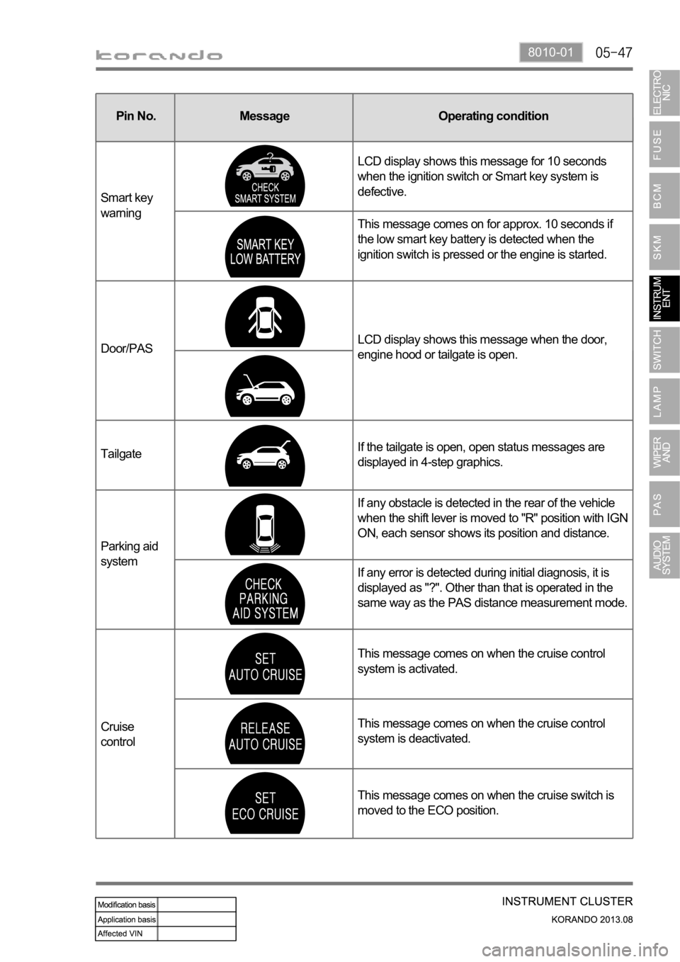
Pin No. Message Operating condition
Domestic Export
Smart key
warningLCD display shows this message for 10 seconds
when the ignition switch or Smart key system is
defective.
This message comes on for approx. 10 seconds if
the low smart key battery is detected when the
ignition switch is pressed or the engine is started.
Door/PASLCD display shows this message when the door,
engine hood or tailgate is open.
Parking aid
systemIf any obstacle is detected in the rear of the vehicle
when the shift lever is moved to "R" position with IGN
ON, each sensor shows its position and distance.
If any error is detected during initial diagnosis, it is
displayed as "?". Other than that is operated in the
same way as the PAS distance measurement mode.
Cruise
controlThis message comes on when the cruise control
system is activated.
This message comes on when the cruise control
system is deactivated.
This message comes on when the cruise switch is
moved to the ECO position.Pin No. Message Operating condition
TailgateIf the tailgate is open, open status messages are
displayed in 4-step graphics.
Page 849 of 1336

Door lock/unlock control by door LOCK switch
When moving the driver or passenger door lock (knob) switch to LOCK from UNLOCK position, BCM
sends the LOCK signal for 0.5 seconds.
When moving the driver or passenger door lock (knob) switch to UNLOCK from LOCK position, BCM
sends the UNLOCK signal for 0.5 seconds.
The LOCK (UNLOCK) operation by the door lock (knob) switch is not available when sending the
LOCK (UNLOCK) signal by any other method such as remote control key.
When reconnecting the battery, the door lock (knob) switch is not operational regardless of the door
lock switch positions.
All doors stay unlocked when receiving the door lock signal in 0.5 seconds after closing the doors. 1.
2.
3.
4.
5.
Page 877 of 1336
Horn (high) Horn (low)
Theft deterrent horn
Theft deterrent horn
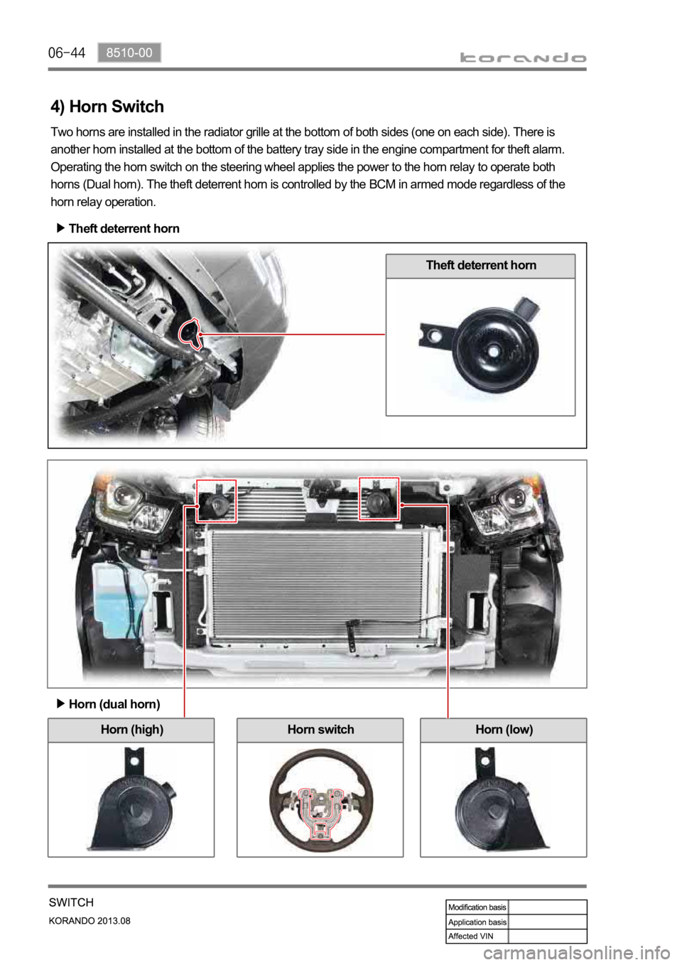
4) Horn Switch
Two horns are installed in the radiator grille at the bottom of both sides (one on each side). There is
another horn installed at the bottom of the battery tray side in the engine compartment for theft alarm.
Operating the horn switch on the steering wheel applies the power to the horn relay to operate both
horns (Dual horn). The theft deterrent horn is controlled by the BCM in armed mode regardless of the
horn relay operation.
Horn (dual horn)
Horn switch
Page 921 of 1336

Front room lamp
2) Operation
Door coupled operation switch: Comes on
when opening door and goes off when closing
with switch pressed
Driver spot lamp switch: Driver front room
lamp comes on when pressing switch
Passenger spot lamp switch: Passenger front
room lamp comes on when pressing switch A.
B.
C.
Center room lamp
Press switch to turn on center room lamp and
press again to turn off it.
It comes on when opening the door with door
coupled operation switch in the front room lamp
pressed even though the switch is in "OFF"
position.
(1) Front room lamp/Center room lamp
Operating the front room lamp and center room lamp switches illuminates the driver/passenger side
lamps and center room lamp.
Room lamp control by door coupled room lamp operation
If a door except the tailgate is opened after the ignition is turned off, provided that door coupled front
room lamp switch is pressed, the front room lamp and center room lamp are illuminated for 2 sec.
and then fade out for 3 sec.
If a door except the tailgate is opened and then closed while the room lamp is fading out, the room
lamp is illuminated for 2 sec. and then fades out for 3 sec. If the ignition is turned on, the room lamp
goes off immediately.
The front room lamp and center room lamp are illuminated for 30 sec. when the door is unlocked by
the REKES or passive door UNLOCK function with IGN OFF and the ignition key removed. If the
REKES or passive door UNLOCK signal is received again, the room lamps are illuminated for
another 30 sec.
The room lamp goes off immediately when the REKES or passive door LOCK signal is received or
the ignition switch is turned to ON position.
If the room lamp is turned on after the ignition key is removed (door open or room lamp switch is
pressed), it is turned off after 10 minutes by the BCM.
When the door open state is changed or the ignition is turned on after the room lamp has been turned
off automatically, the battery saver feature is reset. 1.
2.
3.
4.
5.
Page 961 of 1336
8910-05
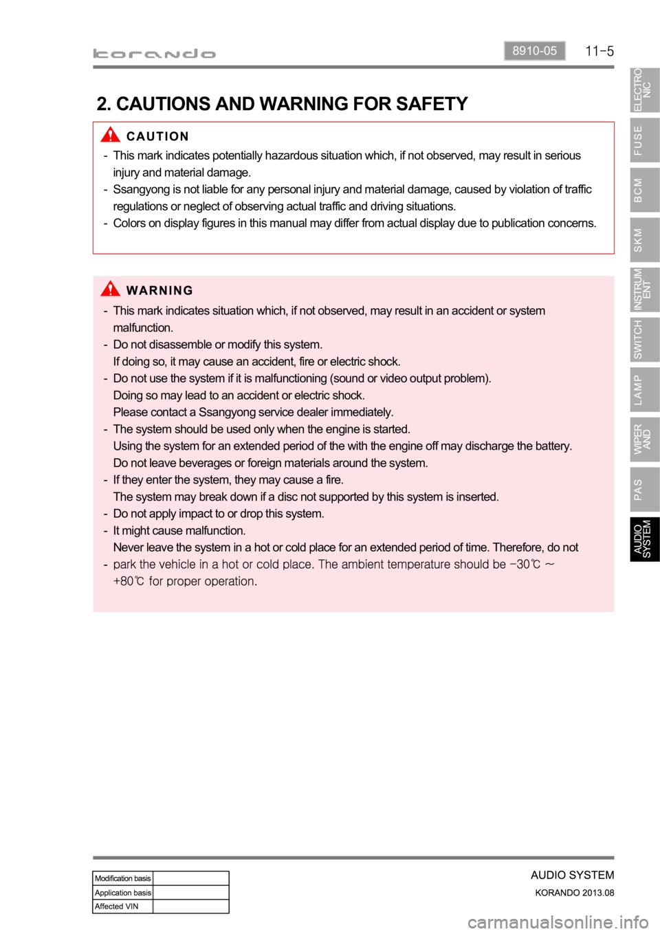
2. CAUTIONS AND WARNING FOR SAFETY
This mark indicates potentially hazardous situation which, if not observed, may result in serious
injury and material damage.
Ssangyong is not liable for any personal injury and material damage, caused by violation of traffic
regulations or neglect of observing actual traffic and driving situations.
Colors on display figures in this manual may differ from actual display due to publication concerns. -
-
-
This mark indicates situation which, if not observed, may result in an accident or system
malfunction.
Do not disassemble or modify this system.
If doing so, it may cause an accident, fire or electric shock.
Do not use the system if it is malfunctioning (sound or video output problem).
Doing so may lead to an accident or electric shock.
Please contact a Ssangyong service dealer immediately.
The system should be used only when the engine is started.
Using the system for an extended period of the with the engine off may discharge the battery.
Do not leave beverages or foreign materials around the system.
If they enter the system, they may cause a fire.
The system may break down if a disc not supported by this system is inserted.
Do not apply impact to or drop this system.
It might cause malfunction.
Never leave the system in a hot or cold place for an extended period of time. Therefore, do not
-
-
-
-
-
-
-
-
Page 984 of 1336
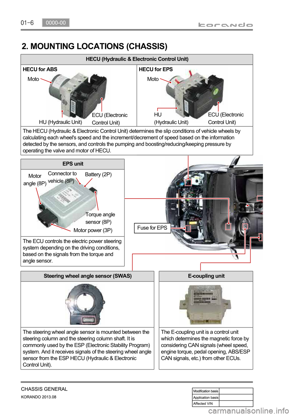
HECU (Hydraulic & Electronic Control Unit)
HECU for ABS HECU for EPS
The HECU (Hydraulic & Electronic Control Unit) determines the slip conditions of vehicle wheels by
calculating each wheel's speed and the increment/decrement of speed based on the information
detected by the sensors, and controls the pumping and boosting/reducing/keeping pressure by
operating the valve and motor of HECU.
2. MOUNTING LOCATIONS (CHASSIS)
Moto
HU (Hydraulic Unit) ECU (Electronic
Control Unit) Moto
HU
(Hydraulic Unit) ECU (Electronic
Control Unit)
Motor
angle (8P)
Motor power (3P)Torque angle
sensor (8P) Battery (2P) Connector to
vehicle (8P)
Fuse for EPS
Steering wheel angle sensor (SWAS)
The steering wheel angle sensor is mounted between the
steering column and the steering column shaft. It is
commonly used by the ESP (Electronic Stability Program)
system. And it receives signals of the steering wheel angle
sensor from the ESP HECU (Hydraulic & Electronic
Control Unit).
EPS unit
The ECU controls the electric power steering
system depending on the driving conditions,
based on the signals from the torque and
angle sensor.
E-coupling unit
The E-coupling unit is a control unit
which determines the magnetic force by
considering CAN signals (wheel speed,
engine torque, pedal opening, ABS/ESP
CAN signals, etc.) from other ECUs.
Page 997 of 1336
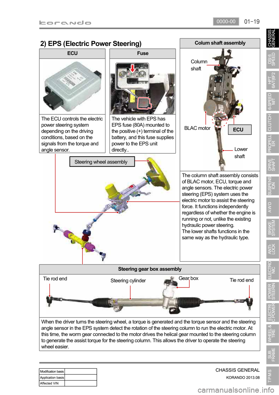
0000-00
ECU
The ECU controls the electric
power steering system
depending on the driving
conditions, based on the
signals from the torque and
angle sensor.
2) EPS (Electric Power Steering)
Fuse
The vehicle with EPS has
EPS fuse (80A) mounted to
the positive (+) terminal of the
battery, and this fuse supplies
power to the EPS unit
directly..
Steering gear box assembly
When the driver turns the steering wheel, a torque is generated and the torque sensor and the steering
angle sensor in the EPS system detect the rotation of the steering column to run the electric motor. At
this time, the worm gear connected to the motor drives the helical gear mounted to the steering column
to generate the assist torque for the steering column. This allows the driver to operate the steering
wheel easier.
ECU
Tie rod end
Tie rod end Gear boxSteering cylinder
Steering wheel assembly
BLAC motor
Lower
shaft Column
shaft
Colum shaft assembly
The column shaft assembly consists
of BLAC motor, ECU, torque and
angle sensors. The electric power
steering (EPS) system uses the
electric motor to assist the steering
force. It functions independently
regardless of whether the engine is
running or not, unlike the existing
hydraulic power steering.
The lower shafts functions in the
same way as the hydraulic type.