SSANGYONG KORANDO 2013 Manual Online
KORANDO 2013
SSANGYONG
SSANGYONG
https://www.carmanualsonline.info/img/67/57503/w960_57503-0.png
SSANGYONG KORANDO 2013 Manual Online
Page 570 of 1336
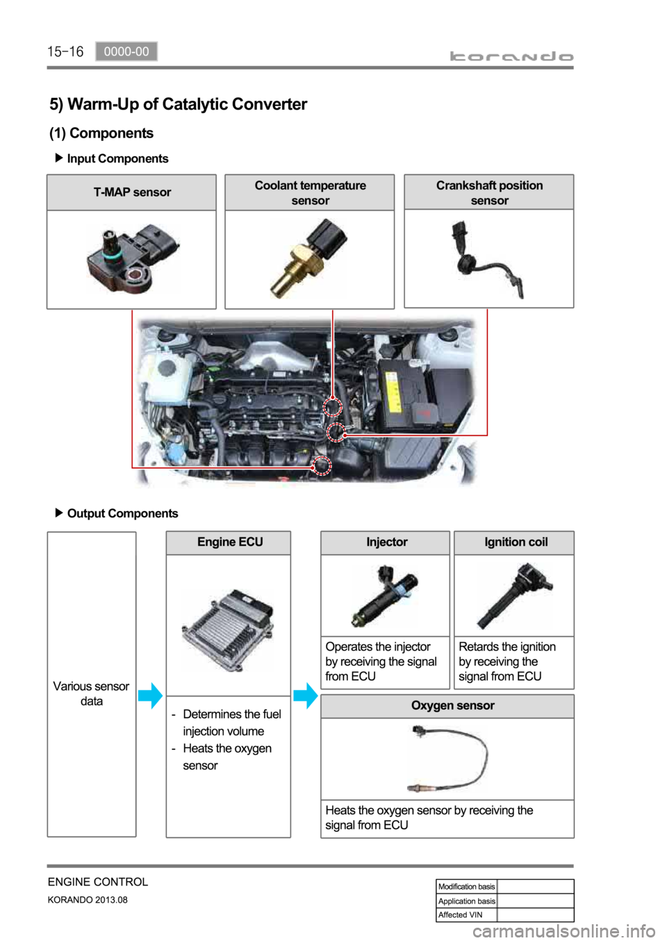
5) Warm-Up of Catalytic Converter
(1) Components
Input Components
T-MAP sensorCoolant temperature
sensorCrankshaft position
sensor
Output Components
Page 572 of 1336
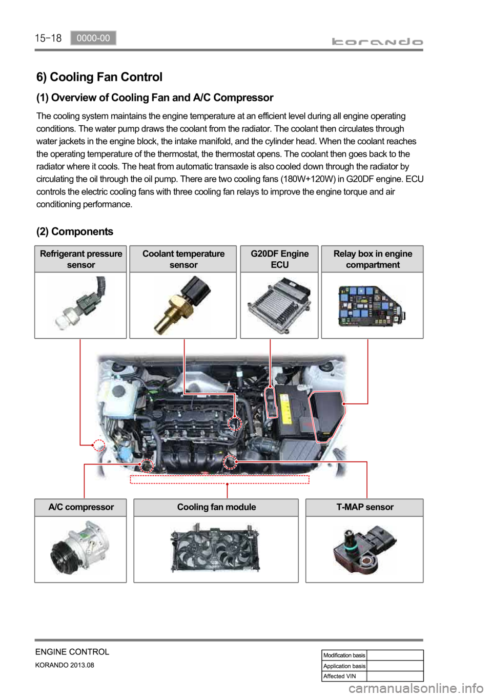
6) Cooling Fan Control
(1) Overview of Cooling Fan and A/C Compressor
The cooling system maintains the engine temperature at an efficient level during all engine operating
conditions. The water pump draws the coolant from the radiator. The coolant then circulates through
water jackets in the engine block, the intake manifold, and the cylinder head. When the coolant reaches
the operating temperature of the thermostat, the thermostat opens. The coolant then goes back to the
radiator where it cools. The heat from automatic transaxle is also cooled down through the radiator by
circulating the oil through the oil pump. There are two cooling fans (180W+120W) in G20DF engine. ECU
controls the electric cooling fans with three cooling fan relays to improve the engine torque and air
conditioning performance.
(2) Components
Refrigerant pressure
sensorCoolant temperature
sensorG20DF Engine
ECURelay box in engine
compartment
A/C compressorCooling fan moduleT-MAP sensor
Page 574 of 1336
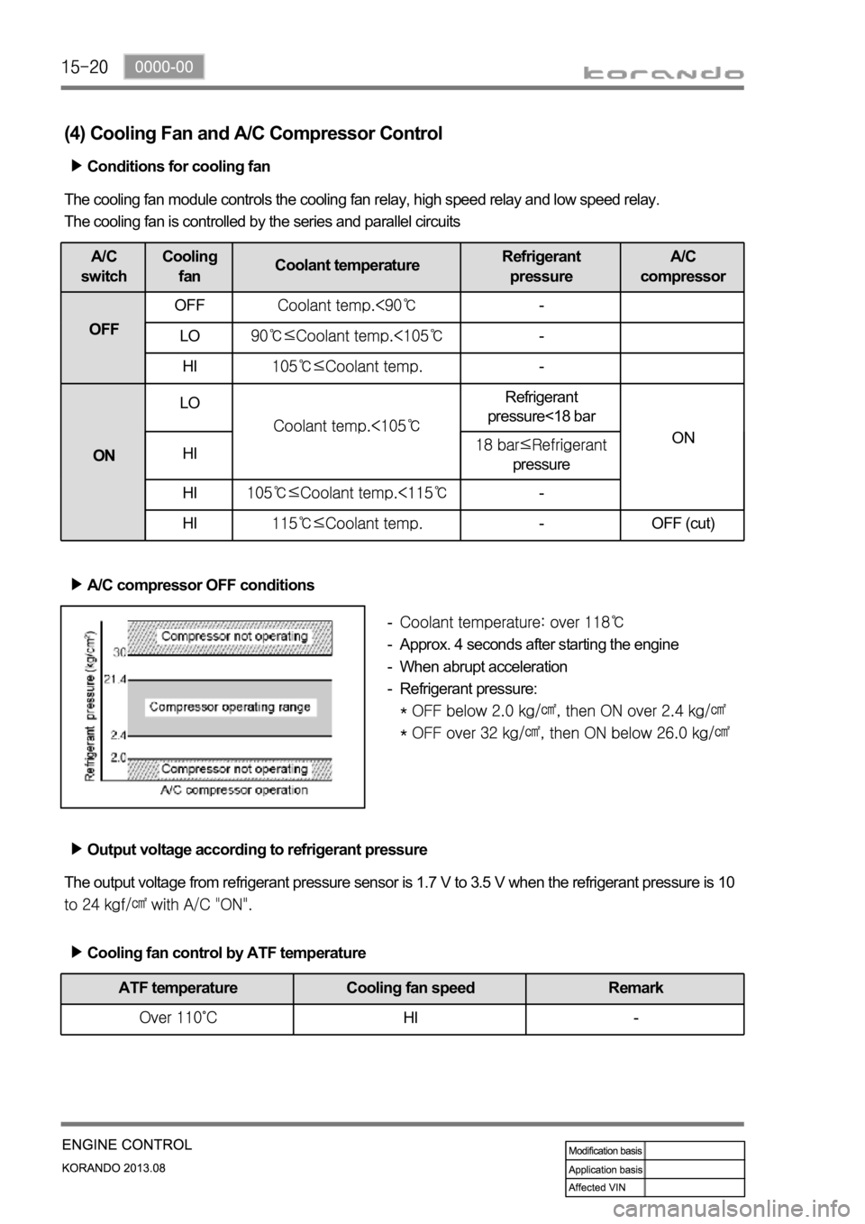
(4) Cooling Fan and A/C Compressor Control
Conditions for cooling fan
The cooling fan module controls the cooling fan relay, high speed relay and low speed relay.
The cooling fan is controlled by the series and parallel circuits
A/C
switchCooling
fanCoolant temperatureRefrigerant
pressureA/C
compressor
OFFOFF
-
LO
-
HI
-
ONLO
Refrigerant
pressure<18 bar
ON
HI
pressure
HI
-
HI
- OFF (cut)
A/C compressor OFF conditions
Approx. 4 seconds after starting the engine
When abrupt acceleration
Refrigerant pressure:
-
-
-
-
Output voltage according to refrigerant pressure
The output voltage from refrigerant pressure sensor is 1.7 V to 3.5 V when the refrigerant pressure is 10
Cooling fan control by ATF temperature
ATF temperature Cooling fan speed Remark
HI -
Page 592 of 1336
0000-00
T-MAP sensor
TurbochargerCDPF
1. MAJOR COMPONENTS (D20DTF(Low CO2))
ECU
Intercooler assemblyAir cleaner assembly
Page 595 of 1336

Swirl control valve
It operates variably in accordance with the
engine load and rpm.
Intake manifold
It is the passage for intake air when the swirl
vale is operating. The T-MAP sensor for
measuring the pressure and temperature of
pressurized air in turbocharger is installed on
the left top of intake manifold.
3. LAYOUT OF INTAKE SYSTEM
1) Overview
The intake system for D20DTF(Low CO2) engine is equipped with a throttle body which includes a flap.
This flap is controlled by an electrical signal to cut off the intake air entering to the engine when the
ignition switch is turned off. The intake manifold contains the swirl control valve and dual port system to
make the optimum turbulence. The T-MAP sensor is located on the left top of the intake manifold and
the HFM sensor for precise control is located at the rear side of air cleaner. To reduce the intake noise
and to improve the intake efficiency, the volume of air cleaner has been increased.
2) Components
Electric throttle body
Page 596 of 1336
0000-00
HFM (Hot Film Air-Mass Sensor)
HFM sensor, version 6
Air cleaner assembly
Its volume is increased and air flowing
efficiency is improved.Intercooler assembly
Its volume is increased and cooling efficiency is
improved.
Page 597 of 1336
0000-00
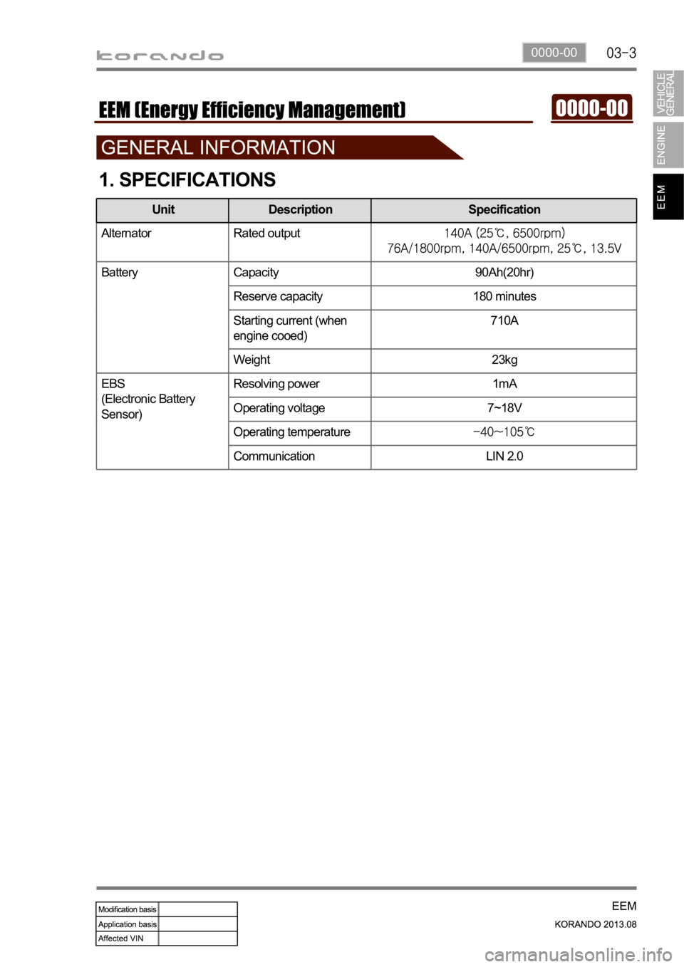
1. SPECIFICATIONS
Alternator Rated output
Battery Capacity 90Ah(20hr)
Reserve capacity 180 minutes
Starting current (when
engine cooed)710A
Weight 23kg
EBS
(Electronic Battery
Sensor)Resolving power 1mA
Operating voltage 7~18V
Operating temperature
Communication LIN 2.0
Unit Description Specification
Page 610 of 1336
1. LAYOUT
D20DTF(Low CO2) D20DTF
ECUBattery sensor (EBS)
Alternator (ALT)
Meter cluster (charge
warning lamp)
Page 629 of 1336
8410-00
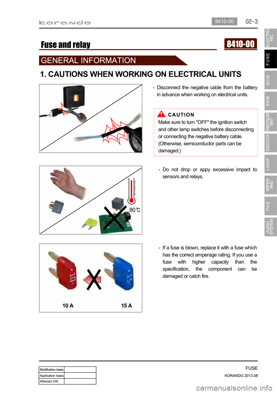
1. CAUTIONS WHEN WORKING ON ELECTRICAL UNITS
Disconnect the negative cable from the battery
in advance when working on electrical units. -
If a fuse is blown, replace it with a fuse which
has the correct amperage rating. If you use a
fuse with higher capacity than the
specification, the component can be
damaged or catch fire. -Do not drop or appy excessive impact to
sensors and relays. -
10 A 15 A
Make sure to turn "OFF" the ignition switch
and other lamp switches before disconnecting
or connecting the negative battery cable.
(Otherwise, semiconductor parts can be
damaged.)
Page 636 of 1336
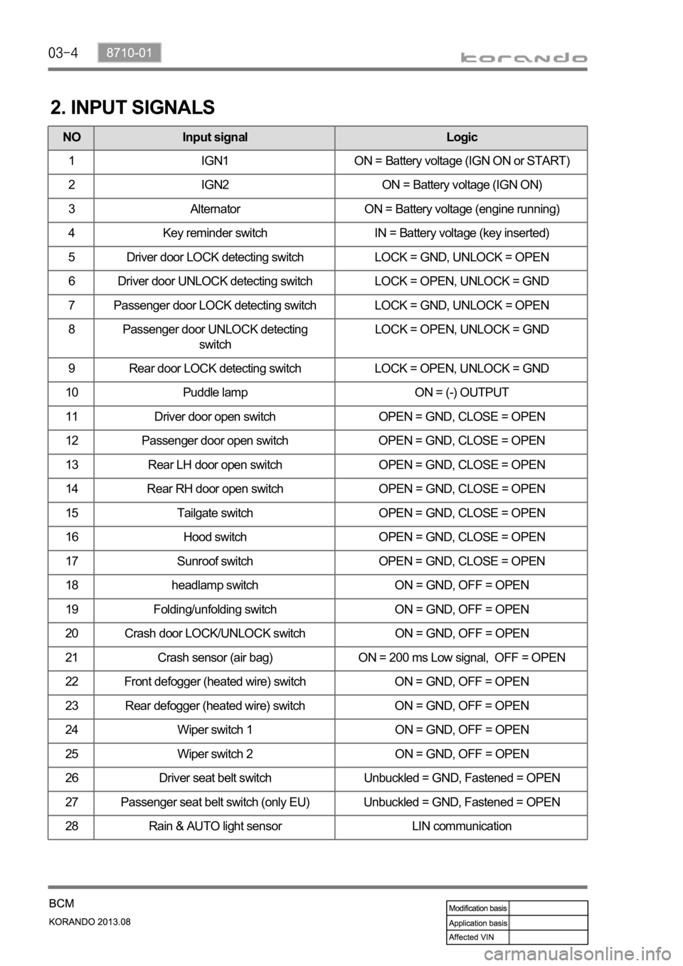
2. INPUT SIGNALS
NO Input signal Logic
1 IGN1 ON = Battery voltage (IGN ON or START)
2 IGN2 ON = Battery voltage (IGN ON)
3 Alternator ON = Battery voltage (engine running)
4 Key reminder switch IN = Battery voltage (key inserted)
5 Driver door LOCK detecting switch LOCK = GND, UNLOCK = OPEN
6 Driver door UNLOCK detecting switch LOCK = OPEN, UNLOCK = GND
7 Passenger door LOCK detecting switch LOCK = GND, UNLOCK = OPEN
8 Passenger door UNLOCK detecting
switchLOCK = OPEN, UNLOCK = GND
9 Rear door LOCK detecting switch LOCK = OPEN, UNLOCK = GND
10 Puddle lamp ON = (-) OUTPUT
11 Driver door open switch OPEN = GND, CLOSE = OPEN
12 Passenger door open switch OPEN = GND, CLOSE = OPEN
13 Rear LH door open switch OPEN = GND, CLOSE = OPEN
14 Rear RH door open switch OPEN = GND, CLOSE = OPEN
15 Tailgate switch OPEN = GND, CLOSE = OPEN
16 Hood switch OPEN = GND, CLOSE = OPEN
17 Sunroof switch OPEN = GND, CLOSE = OPEN
18 headlamp switch ON = GND, OFF = OPEN
19 Folding/unfolding switch ON = GND, OFF = OPEN
20 Crash door LOCK/UNLOCK switch ON = GND, OFF = OPEN
21 Crash sensor (air bag) ON = 200 ms Low signal, OFF = OPEN
22 Front defogger (heated wire) switch ON = GND, OFF = OPEN
23 Rear defogger (heated wire) switch ON = GND, OFF = OPEN
24 Wiper switch 1 ON = GND, OFF = OPEN
25 Wiper switch 2 ON = GND, OFF = OPEN
26 Driver seat belt switch Unbuckled = GND, Fastened = OPEN
27 Passenger seat belt switch (only EU) Unbuckled = GND, Fastened = OPEN
28 Rain & AUTO light sensor LIN communication
