SSANGYONG MUSSO 1998 Workshop Repair Manual
Manufacturer: SSANGYONG, Model Year: 1998, Model line: MUSSO, Model: SSANGYONG MUSSO 1998Pages: 1463, PDF Size: 19.88 MB
Page 691 of 1463

1F2-42 M161 ENGINE CONTROLS
Pin No.
61
62
63
64
65
66
67
68
69
70
71
72
73
74
75
76
77
78
79
80
81
82
83
84
85
86
87
88
89
90
Abbreviation Description
-
-
Injector-cylinder 1
Injector-cylinder 2
Injector-cylinder 3
Injector-cylinder 4
E-GAS motor plus
E-GAS motor minus
Power ground TM.31
-
Ignition coil cylinder 2+3
Ignition coil cylinder 1+4
Camshaft control
-
Second air pump relay
-
Engine coolant temperature
Temperature ground
Intake air temperature
Hot film air mass signal
-
-
E-GAS potentiometer ground
E-GAS potentiometer 2 signal
-
E-GAS potentiometer 1 signal
-
-
-
-
-
EV1
EV4
EV2
EV3
M+
M-
TM.31
-
ZSB23
ZSA14
NWS
-
-
SLP
-
MT
GND
LT
HFM
-
-
-
IP2S
-
IP1S
-
-
--
-
l
l
l
l
l
l
l
-
l
l
l
-
-
¡
-
l
l
l
l
-
-
l
l
-
l
-
-
-
-
-
l
l
l
l
l
l
l
-
l
l
l
-
-
¡
-
l
l
l
l
-
-
l
l
-
l
-
-
-
E23 ENG,
4speed A/T E23 ENG,
5speed A/T
Page 692 of 1463

M161 ENGINE CONTROLS 1F2-43
Pin No.Abbreiation Description
-
-
-
-
-
-
-
-
Crankshaft sensor ground
Crankshaft sensor signal
-
-
-
Camshaft sensor ground
Hot film air mass ground
Camshaft sensor signal
-
Hot film air mass supply
-
-
-
E-GAS potentiometer supply
-
-
-
-
Knock sensor 1 ground
Knock sensor 1 signal
-
-
91
92
93
94
95
96
97
98
99
100
101
102
103
104
105
106
107
108
109
11 0
111
11 2
11 3
11 4
11 5
11 6
11 7
11 8
11 9
120-
-
-
-
-
-
-
-
KW-
KW+
-
-
-
NOWE-
GND
NOWE+
-
V-REF.HFM
-
-
-
V-REF.DK
-
-
-
-
GND
KS1
-
-
-
-
-
-
-
-
-
-
l
l
-
-
-
l
l
l
-
l
-
-
-
l
-
-
-
-
l
l
-
--
-
-
-
-
-
-
-
l
l
-
-
-
l
l
l
-
l
-
-
-
l
-
-
-
-
l
l
-
-
E23 ENG,
4speed A/T E23 ENG,
5speed A/T
-
-
-
-
-
-
-
-
l
l
-
-
-
l
l
l
-
l
-
-
-
l
-
-
-
-
l
l
-
-
E23 ENG,
4speed A/T
Page 693 of 1463

1F2-44 M161 ENGINE CONTROLS
Removal & Installation Procedure
· ·· ·
·When removing the ECU only
1. Turn the ignition switch to "OFF" position.
2. Disconnect the negative battery cable.
3. Disconnect the couplings from ECU.
4. Unscrew the left and right bolt (3) on bolt (1) and auxiliarly
bracket and remove the auxiliarly bracket from the bracket
assembly (2).
Installation Notice
5. Unscrew the four bolts (5) and disconnect the ECU (6) from
the bracket assenbly.
Installation Notice
6. Installation should follow the removal procedure in the
reverse order.
Tightening Torque6 - 8 Nm
5 - 7 Nm(1)
(3)
Tightening Torque 5 - 7 Nm
8. Unscrew the bolts (5) and disconnect the ECU (6) from the
bracket assenbly.
Installation Notice · ·· ·
·When Removing the ECU with ABS or ABS/ASR Unit
1. Turn the ignition switch to "OFF" position.
2. Disconnect the negative battery cable.
3. Disconnect the couplings from ECU.
4. Disconnect the coupling from ABS or ABS/ASR unit.
5. Unscrew the bolt (1) and the left and right flange nuts.
6. Remove the ECU with ABS or ABS/ASR unit assembly.
7. Unscrew the left and right bolt (3) on the auxiliary bracket
and remove the auxiliary bracket from the bracket assembly.
Installation Notice
Tightening Torque 6 - 8 Nm
Tightening Torque 5 - 7 Nm
Tightening Torque 5 - 7 Nm
9. Installation should follow the removal procedure in the
reverse order.
Page 694 of 1463

M161 ENGINE CONTROLS 1F2-45
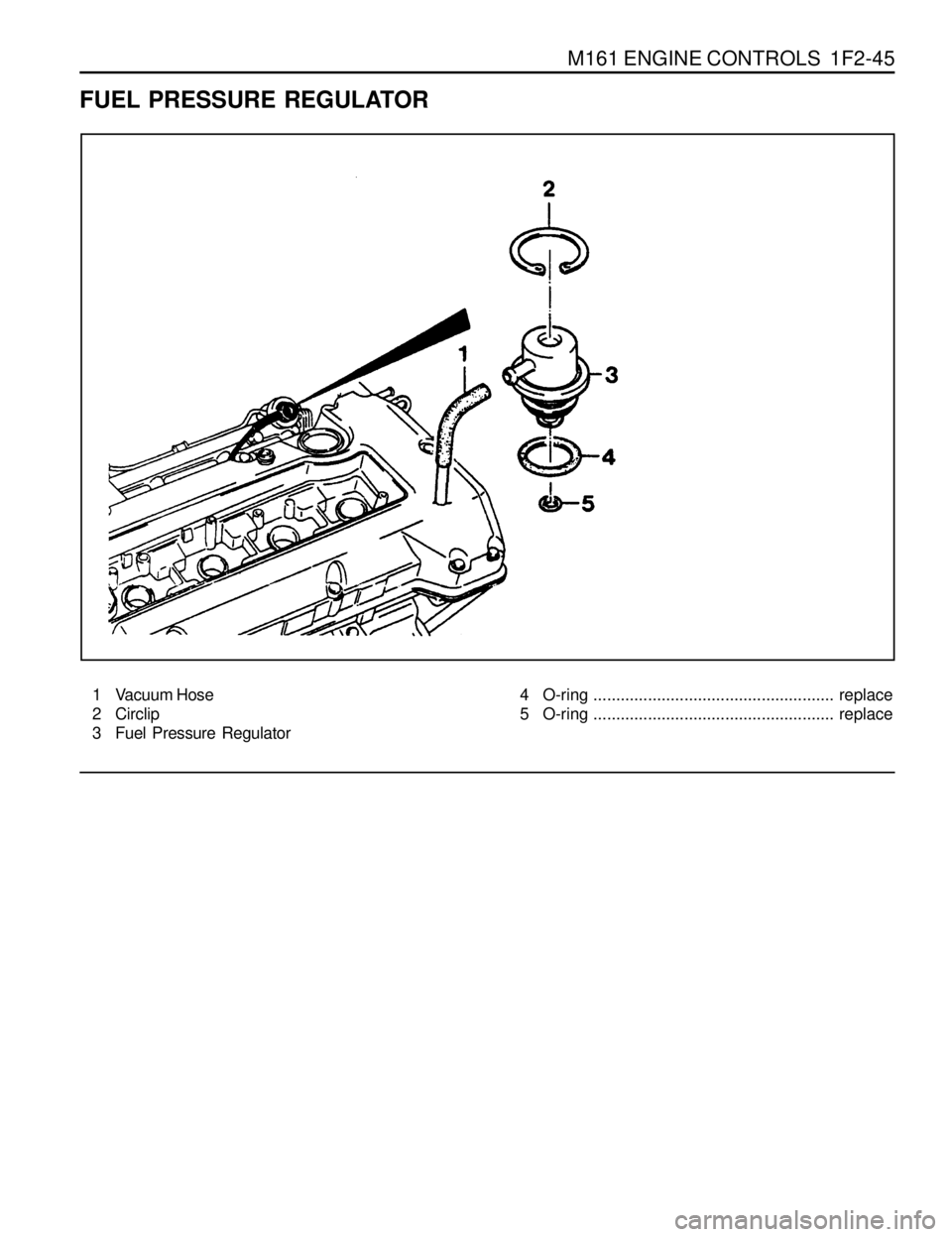
1 Vacuum Hose
2 Circlip
3 Fuel Pressure Regulator
FUEL PRESSURE REGULATOR
4 O-ring ..................................................... replace
5 O-ring ..................................................... replace
Page 695 of 1463

1F2-46 M161 ENGINE CONTROLS
3. Disconnect the vacuum hose.
4. Disconnect the circlip and remove the fuel pressure
regulator.
5. Apply the oil to O-ring lightly and then replace it.
6. Installation should follow the removal procedure in the
reverse order.
7. Check for fuel pressure and internal leaks by operating the
engine. 2. Discharge the pressure in fuel supply system by pressing
the service valve.
Removal & Installation Procedure
1. Remove the fuel pressure test connector.
Page 696 of 1463

M161 ENGINE CONTROLS 1F2-47
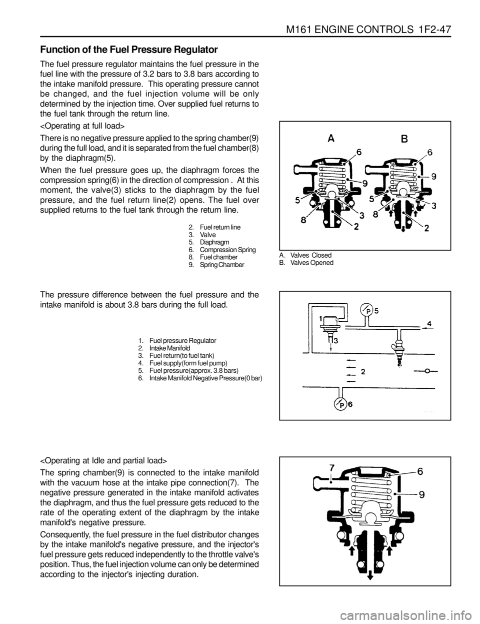
A . Valves Closed
B. Valves Opened
The pressure difference between the fuel pressure and the
intake manifold is about 3.8 bars during the full load.
The spring chamber(9) is connected to the intake manifold
with the vacuum hose at the intake pipe connection(7). The
negative pressure generated in the intake manifold activates
the diaphragm, and thus the fuel pressure gets reduced to the
rate of the operating extent of the diaphragm by the intake
manifold's negative pressure.
Consequently, the fuel pressure in the fuel distributor changes
by the intake manifold's negative pressure, and the injector's
fuel pressure gets reduced independently to the throttle valve's
position. Thus, the fuel injection volume can only be determined
according to the injector's injecting duration.
2. Fuel return line
3. Valve
5. Diaphragm
6. Compression Spring
8. Fuel chamber
9. Spring Chamber
1. Fuel pressure Regulator
2. Intake Manifold
3. Fuel return(to fuel tank)
4. Fuel supply(form fuel pump)
5. Fuel pressure(approx. 3.8 bars)
6. Intake Manifold Negative Pressure(0 bar)
Function of the Fuel Pressure Regulator
The fuel pressure regulator maintains the fuel pressure in the
fuel line with the pressure of 3.2 bars to 3.8 bars according to
the intake manifold pressure. This operating pressure cannot
be changed, and the fuel injection volume will be only
determined by the injection time. Over supplied fuel returns to
the fuel tank through the return line.
There is no negative pressure applied to the spring chamber(9)
during the full load, and it is separated from the fuel chamber(8)
by the diaphragm(5).
When the fuel pressure goes up, the diaphragm forces the
compression spring(6) in the direction of compression . At this
moment, the valve(3) sticks to the diaphragm by the fuel
pressure, and the fuel return line(2) opens. The fuel over
supplied returns to the fuel tank through the return line.
Page 697 of 1463

1F2-48 M161 ENGINE CONTROLS
The pressure difference between the fuel pressure and
the intake manifold is approx. 3.2 bars during idling.
1. Fuel pressure Regulator
2. Intake Manifold
3. Fuel Return(to fuel tank)
4. Fuel Supply(from fuel pump)
7. Fuel Pressure(approx. 3.2 bars)
8. Intake Manifold Negative Pressure(0.6 bars)
A. Fuel pressure
B. Intake Manifold Negative Pressure
LL. Idling
TL. Partial load
VL. Full load
Page 698 of 1463

M161 ENGINE CONTROLS 1F2-49
FUEL DISTRIBUTOR
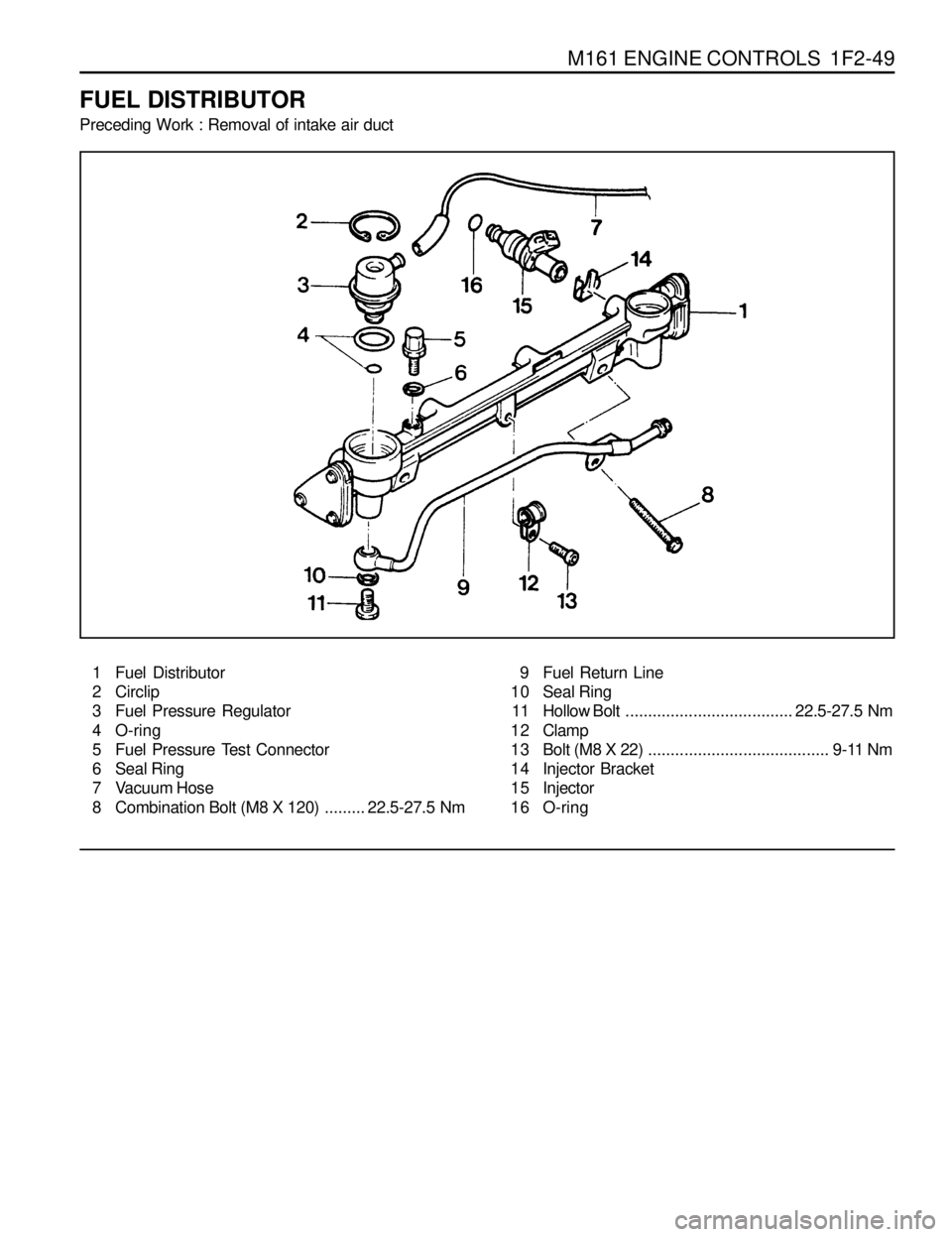
Preceding Work : Removal of intake air duct
1 Fuel Distributor
2 Circlip
3 Fuel Pressure Regulator
4 O-ring
5 Fuel Pressure Test Connector
6 Seal Ring
7 Vacuum Hose
8 Combination Bolt (M8 X 120).........22.5-27.5 Nm9 Fuel Return Line
10 Seal Ring
11 Hollow Bolt.....................................22.5-27.5 Nm
1 2 Clamp
13 Bolt (M8 X 22)........................................ 9-11 Nm
14 Injector Bracket
15 Injector
16 O-ring
Page 699 of 1463

1F2-50 M161 ENGINE CONTROLS
Tightening Torque
22.5 - 27.5 Nm
Tightening Torque22.5 - 27.5 Nm
Removal & Installation Procedure
1. Discharge the fuel pressure from the fuel pressure test
connector by pushing service valve (arrow).
2. Disconnect the battery ground cable.
3. Disconnect the vacuum hose from the fuel pressure
regulator.
4. Disconnect the cable from ignition coil.
5. Remove the fuel return and supply line.
Installation Notice
Notice
lFor removal, cover around parts with cloths not to
bestained by fuel.
lIn case of checking the injector only, do not remove the
fuel return and supply line.
6. Remove the four injector connectors (arrows).
7. Unscrew the two combination bolts (8).
Installation Notice
Page 700 of 1463

M161 ENGINE CONTROLS 1F2-51
9. Installation should follow the removal procedure in the
reverse order.
10. Check for fuel pressure and internal leakage by operating
the engine. 8. Pull out the injector from intake manifold and remove the
fuel distributor.
Notice
Replace the injector O-ring with new one.
Ignition Coil & Cable
lIgnition coil T1/1 No.1 cylinder + No.4 cylinder
lInition coil T1/2 No.1 cylinder + No.4 cylinder