engine oil SSANGYONG MUSSO 2003 Service Manual
[x] Cancel search | Manufacturer: SSANGYONG, Model Year: 2003, Model line: MUSSO, Model: SSANGYONG MUSSO 2003Pages: 1574, PDF Size: 26.41 MB
Page 245 of 1574

M161 ENGINE MECHANICAL 1B2-93
CONNECTING ROD Preceding Work : Removal of piston
1 Connecting Rod Bushing
2 Oil Gallery
3 Balance Weight
4 Connecting Rod Bolt(M9 x 52, 8 pieces) ............1st step 40 Nm
2nd step 90 °
5 Fit Sleeve
6 Upper Connecting Rod Bearing
7 Lower Connecting Rod Bearing
8 BearingShell Lug
9 Marking [Indication(//) or Numbers]
Service Data Standard
Distance (L) from The Connecting Rod Bearing to Bushing Bore Center Width of The Connecting Rod (B) at Bearing Bore Width of The Connecting Rod (b) at Bushing BoreBasic Bore at The Bearing Shell (D1)Basic Bore at The Bushing (d1) Bushing Inner Diameter (d) Clearance Between The Piston Pin and The BushingPeak-to-valley Height of Connecting Rod Bushing on InsidePermissible Wwist of Connecting Rod Bearing Bore toConnecting Rod Bushing Bore Permissible Deviation of Axial Paralleism of Connecting Rod Bearing Bore to Connecting Rod Bushing Bore
Permissible Deviation of Axial Paralleism of Connecting Rod Bearing Bore fromConcentricity
Permissible Difference of Each Connecting Rod in Weight E20 : 154 mm
E23 : 149 ± 0.05 mm 21.940 - 22.000 mm 21.940 - 22.000 mm 51.600 - 51.614 mm24.500 - 24.571 mm22.007 - 22.013 mm 0.007 - 0.018 mm
0.005 mm
0.1/100 mm
0.045/100 mm
0.01 mm0.4 g
Page 247 of 1574

M161 ENGINE MECHANICAL 1B2-95
PISTON RING Preceding Work : Removal of piston
1 Piston Compression Ring (Top Ring)
2 Piston Compression Ring (2nd Ring)
3 Piston Oil Ring 4-
5 Spacer
6 Side Rail
Notice If out of specification, replace the piston ring.
Tools Required
000 589 51 37 00 Clamping Strap
Replacement Procedure
1. Measure the piston ring ’s gap.
Gap Between The Piston and The Piston Ring
Groove 1 0.20 - 0.40 mm Groove 2 0.20 - 0.40 mm Groove 3 0.20 - 0.45 mm
Groove 1 0.028 - 0.060 mm Groove 2 0.010 - 0.045 mmGroove 3 0.010 - 0.045 mmEnd Gap of The Piston Ring
Page 248 of 1574

1B2-96 M161 ENGINE MECHANICAL
2. Remove the piston ring with a pliers.
3. For installation, position the piston ring to be the ‘TOP ’
mark on the piston ring upward and arrange the piston ring ends to be 120 ° apart.
4. Adjust the hook spring joint in the oil ring 180 ° away from
the ring end.
Clamping Strap 000 589 51 37 00
Page 249 of 1574

M161 ENGINE MECHANICAL 1B2-97
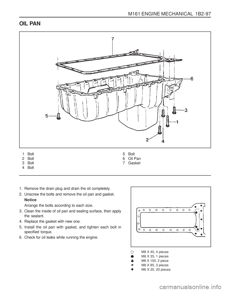
OIL PAN
1 Bolt
2 Bolt
3 Bolt
4 Bolt
1. Remove the drain plug and drain the oil completely.
2. Unscrew the bolts and remove the oil pan and gasket. Notice Arrange the bolts according to each size.
3. Clean the inside of oil pan and sealing surface, then apply the sealant.
4. Replace the gasket with new one.
5. Install the oil pan with gasket, and tighten each bolt in specified torque.
6. Check for oil leaks while running the engine.
M8 X 40, 4 pieces M6 X 35, 1 piecesM6 X 100, 2 pieceM6 X 85, 3 piecesM6 X 20, 20 pieces5 Bolt
6 Oil Pan
7 Gasket
�
Page 250 of 1574

1B2-98 M161 ENGINE MECHANICAL Oil Circulation
1 Oil Strainer
2 Oil Pump
3 Oil Pan
4 Oil Non-Return Valve
5 Oil Filter
6 Oil Filter Bypass Valve
7 Main Oil Gallery
8 Closing Ball (
� 15mm)
9 Crankshaft
10 Connecting Rod Bearing 11 Crankshaft Bearing
12 Connecting Rod
13 Piston
14 Oil Spray (Piston Crown Area)
15 Non-Return Valve (Crankcase) 16 Oil Supply (To Chain Tensioner)
1 7 Camshaft
18 Cam Bearing
19 Valve
20 Oil Gallery (Supply Oil to Intake Tappet)
21 Oil Gallery (Supply Oil to Exhaust Tappet)
22 Ball (
� 8mm)
23 Camshaft Plug
24 Seal
25 Screw Plug
26 Oil Return Gallery (Cylinder Head and
Crankcase)
27 Oil Return Gallery (Crankcase)
28 End Cover (
� 20mm)
29 Oil Return Pipe
Page 251 of 1574

M161 ENGINE MECHANICAL 1B2-99
ENGINE OIL AND OIL FILTER ELEMENT
1 Oil Filter Cover.......................................... 25 Nm
2 O-ring .................................................... Replace
3 Oil Filter Element4 Oil Drain Plug
5 Oil Filter Bypass Valve
6 Oil Filter Cap
Page 252 of 1574

1B2-100 M161 ENGINE MECHANICAL9. Fill up engine oil through the engine oil filler opening.
10. Check for oil leaks at normal engine temperature after starting the engine.
11. Stop the engine and wait 5 minutes. Check the oil level and fill up as specified if necessary.
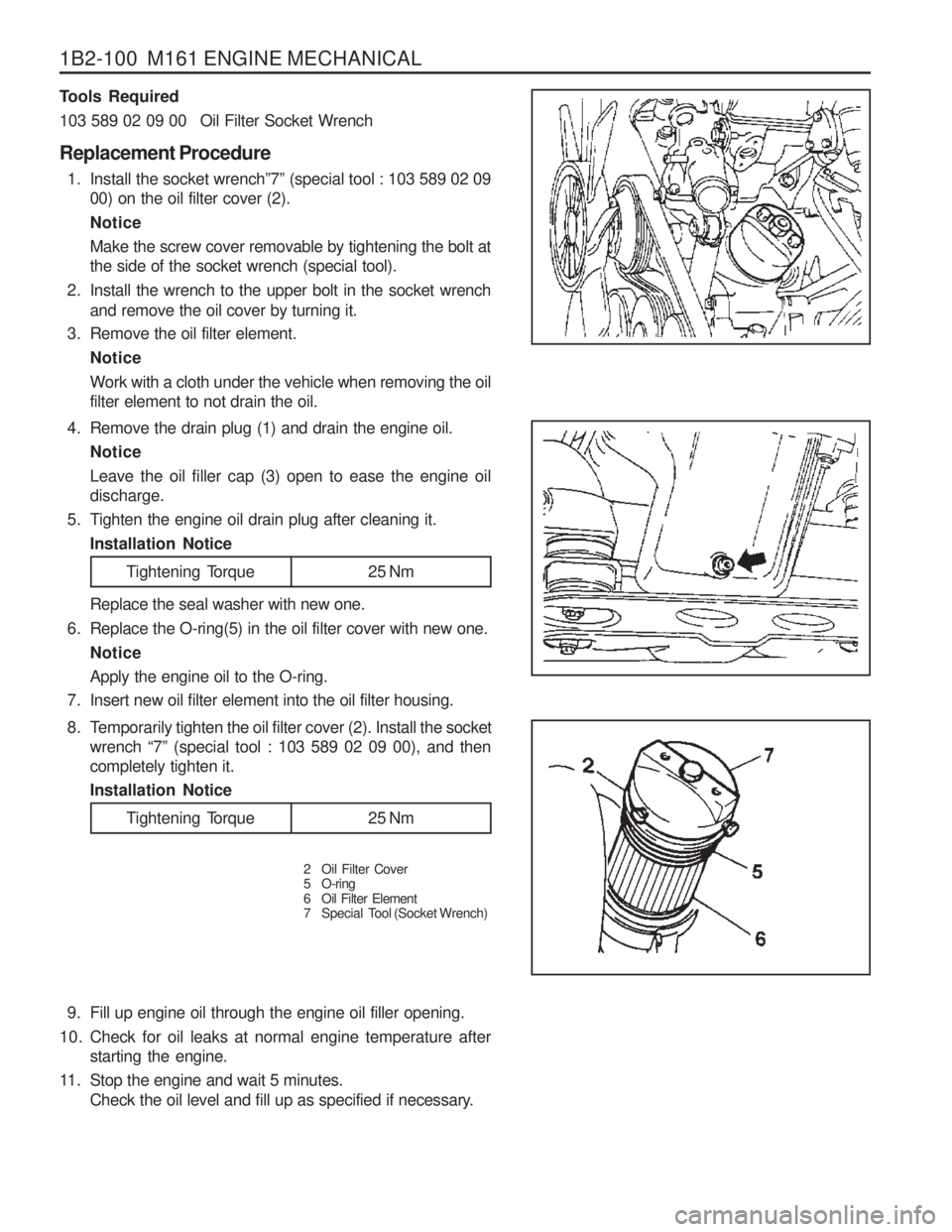
4. Remove the drain plug (1) and drain the engine oil.
Notice Leave the oil filler cap (3) open to ease the engine oil discharge.
5. Tighten the engine oil drain plug after cleaning it. Installation Notice
Tools Required
103 589 02 09 00 Oil Filter Socket Wrench Replacement Procedure
1. Install the socket wrench ”7” (special tool : 103 589 02 09
00) on the oil filter cover (2). NoticeMake the screw cover removable by tightening the bolt at the side of the socket wrench (special tool).
2. Install the wrench to the upper bolt in the socket wrench and remove the oil cover by turning it.
3. Remove the oil filter element.
Notice Work with a cloth under the vehicle when removing the oil filter element to not drain the oil. Replace the seal washer with new one.
6. Replace the O-ring(5) in the oil filter cover with new one.
Notice Apply the engine oil to the O-ring.
7. Insert new oil filter element into the oil filter housing.
Tightening Torque 25 Nm
8. Temporarily tighten the oil filter cover (2). Install the socket wrench “7” (special tool : 103 589 02 09 00), and then
completely tighten it. Installation Notice
2 Oil Filter Cover
5 O-ring
6 Oil Filter Element
7 Special Tool (Socket Wrench)
Tightening Torque 25 Nm
Page 253 of 1574

M161 ENGINE MECHANICAL 1B2-101
OIL PUMP Preceding Work : Removal of oil pan
1 Bolt (M8 X 35, 3 piece)...................22.5-27.5 Nm
2 Oil Pump
3 Oil Strainer Assembly
4 Bolt (M6 X 12, 2 pieces) ......................... 9-11 Nm
(In E23 Engine, These Bolts areCombined with Baffle Plate)
5 Bolt (M8 X 20, 1 pieces) ....................... 29-35 Nm 6 Washer
7 Sprocket (Oil Pump Drive)
8 Chain (Oil Pump Drive)
9 Plate-Baffle
10 Bolt (M6 X 12, 6 piece) ........................... 9-11 Nm
(E23 Engine Only : Baffle Plate Mounting Bolt)
Page 254 of 1574

1B2-102 M161 ENGINE MECHANICAL
Removal & Installation Procedure
1. Unscrew the bolt (6) from the oil pump drive sprocket andseparate the oil pump drive chain. Installation Notice
Tightening Torque Bolt (4) 9 - 11 Nm
Bolt (5) 9 - 11 Nm
Tightening Torque 29 - 35 Nm
2. Unscrew the bolts (4,5) and remove the oil strainer assembly (3). Installation Notice Insert the steel gasket into the oil pump and bolt (4) mounting surface.
3. Unscrew the six bolts (11) and remove the haffle plate. Installation Notice
Tightening Torque 9 - 11 Nm
4. Unscrew the three bolt (1) and remove the oil pump. Installation Notice
Tightening Torque 22.5 - 27.5 Nm
Page 255 of 1574

M161 ENGINE MECHANICAL 1B2-103
OIL PRESSURE RELIEF VALVE Preceding Work : Removal of oil pan
1 Screw Plug................................................ 50 Nm
2 Compression Spring
Removal & Installation Procedure
1. Remove the screw plug (1). Installation Notice
2. Remove the spring (2), guide pin (3) and the piston (4).
3. Installation should follow the removal procedure in the reverse order. Notice Don ’t use the seal for the screw plug. 3 Guide Pin
4 Piston
Tightening Torque 50 Nm